Connexite documentation
Imported from the Connexite public documentation portal. Original hub: https://support.connexite.co.uk/landing.html.
Use the sections below for Synapse CLI, Synapse Web UI, and ConnexGate material.

SQL schemes can be validated with ConnexOne database application control
Imported from the Connexite public documentation portal. Original hub: https://support.connexite.co.uk/landing.html.
Use the sections below for Synapse CLI, Synapse Web UI, and ConnexGate material.
Modbus protocol is widely used in manufacturing environment such as automative industry, energy conversion plants, machinery networks and other industrial environments. Data generated within production zones, are now becoming more and more relevant for the business process management and optimization. Although modbus protocols is relatively old, it is still the de-facto protocol to share data within production related environments, thanks to evolved structure of the protocol with TCP support. Supervisory Control and Data Acquisition, shortly SCADA systems, are using information from different data generation, to mostly control the production processes. Evolving business flows requires information from every aspect of production tools. This data then used to analyse the efficiency, quality and performance of overall processes as part of lifecycle managements. This is why it is crucially important to transfer the data from production environment for further analysis, while keeping the machinery network isolated from any incoming threats.
For more information about MODBUS protocol, please follow this wikipedia link.
Modbus is indeed a very old (late 1970s) protocol that was created for the communication between among programmable logic controllers, PLC. It is based on a master/slave relation. That means a device acting as master, polls slave devices to read or write information. Registers are data storage repository defined with a register reference address and are slave specific only. Old Modbus implementations are based on serial communication, but today with the spread of network based communication, Modbus also evolved to be operated on TCP/IP networks. Arrow supports TCP based modbus operations, so this document will be restricted to only network side of modbus protocol and focused on Arrow operation.
Similar to other client/server applications, modbus master sends out a request to slave address with a specific function code, register number and count. This requests inform the slave about information to be received by master. The request and response is very similar to each other and are in the following format.
| Device Address |
| Function Code |
| Register Number |
| Register Count |
| Data |
| Checksum |
There are different types of register. Function code defines what type of register information exchange will be triggered. The most common function belongs to the operation of “reading holding registers”, and it is 3 (three). This function allows the master to request one or more holding register stored values. Similarly code 16 is used to write into holding registers.
Arrow is built to relay information between two security zones with different level of criticality. MODBUS slave devices, are usually used to store and use information in an operating environmnet consisting of machinery, production tools, manufacturing and processing engines and analysis systems. Since the information is not only used to provide metrics but also to inform the tools or machines about their operation, no external manipulating device should reside in this critical production environment. So the risk with any externally connected device is not acceptable. Yet the information created in this environment can possess crucial value for business flows, and is required to be transferred out for further processing.
This is where Arrow gets into the picture. Arrow speaks with modbus slaves (PLC, machines, tools etc.), retrieve the information and sends this information to its twin sister into corporate IT network, where information is processed into more readable and valuable format.
Here is a simple illustration of how Arrow works in a modbus environment:

Figure 1 – Simple production environment, where modbus data is read from PLC and sends out analysis tools
Arrow architecture is based on separate services, and modbus is one of IOT services that turns the receiving end device (guardian) into a modbus master. Arrow Guardian polls the slave devices, receives register values, and sends to other end pair (postman) using its very own transfer technologies. On the other network Arrow Postman, receives information, and creates a virtual modbus slave to provide information for IT side modbus masters. Other infomration exchange methods can be implemented to share modbus retrieved informations, thanks to ArrowOS, flexible architecture. For each slave device to read information on Guardian side, there exists a virtual device to relay it in the Postman side.
Flow of information retrieval and sharing is visualized in the following illustration:

Figure 2 – Steps to retrieve information and share with external tools
Here are the steps for the information relay process:
For more information on how to configure Arrow devices for modbus operation, please follow this link to access modbus configuration guide.
Arrow modbus transfer flow is based to create virtual copies of physical modbus supported devices such as programmable logic controllers (PLC). Modbus configuration menu is shown if you already have a SCADA license.

IOT/Scada menu includes all the configuration you need to transfer modbus informations. Menu items and their functions are as follow:
| Data Collect | Modbus collection and transfer rule sets |
| Virtual Devices | Postman side virtual PLC devices to read data retrieved from physical PLC on Gurdian side |
| Web Receivers | Postman side web API receivers to send modbus data from physical PLC devices |
| Latest Data | Last data retrieved from all PLC devices |
| Device Add/Remove | Add/Remove physical devices to read data |
| IOT Settings | Global settings related with IOT/Modbus operation |
Please browse through sub sections to get more information about modbus operation
Arrow basic modbus process creates a simulated modbus network by starting virtual devices on Postman side. Every PLC would have its shadow copy on unrestricted network, allowing data stored in the actual PLC device to be accessible by business or reporting tools while keeping it safe from tampering.
Arrow Guardian is responsible with reading data from individual modbus slaves, encapsulate into a transferrable format and send it to Postman from the fiber interconnection. Last information is stored in Postman memory for a period of refresh time interval defined in Guardian IOT settings menu. Neither Guardian nor Postman writes the retrieved information into a permanent datastore, preventing any data leak. Data requester ask register informations from Postman using standart Modbus protocol. If Guardian stops sending information for one modbus slave, Postman also stops providing this information and return relevant error codes.
In case a virtual PLC device is removed from rule sets defined in Guardian “Data Collect” menu, this virtual device will be removed from Postman and unaccessible error code would return if any receiver tries to ask information from this virtual device.
You can create up to 20 virtual devices per pair. This number will be increased in following versions.
Angora way of managing a product is to keep it simple, and request as few as possible input from users and administrator. Arrow is no exception to that mentality. There are only couple of parameters to be defined if only needed to change from default values.
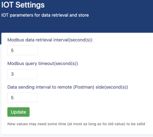
IOT Settings menu includes, timer parameters that may be needed to tune based on specific deployments.
| Parameter | Description |
|---|---|
| Modbus data retrieval interval | Time interval that Guardian asks slave devices about current register values. This changes the latest data information in Guardian |
| Modbus query timeout | Time interval that Guardian checks if there are any rule changes in data collection set |
| Data sending interval | Time interval for Guardian to send data to Postman. This value would be better match with modbus data retrieval to keep both sides synchronized. |
Arrow modbus operation consists of couple of steps. First you must add modbus supported devices from add/remove devices menu. Then you must create virtual devices to simulate physical devices on Guardian at the Postman side. Please keep in mind that physical devices are always residing behind Guardian, and their simulated shadow, virtual devices are running on Postman.
After both side devices are ok, you should create mappings from data collect menu. Optionally you can tune transfer parameters from IOT settings. Please follow next sections to find out about details of device creation and rule sets.
| Version Number | 23-1401-A |
| Release Date | 12.12.2023 |
| Fixed Bugs | None |
| New Features | Service options added > SNMP service can be enabled/disabled > HTTP service can be enabled/disabled > SSH service port can be changed from default > HTTPS service port can be changed from default |
| Version Number | 23-1361-G |
| Release Date | 4.12.2023 |
| Fixed Bugs | None |
| New Features | OPC Data Transfer functionality has added with single instance |
| Version Number | 23-1314-B |
| Release Date | 6.08.2023 |
| Fixed Bugs | None |
| New Features | Modbus functionality nas improved to support 20 devices SQL table controls has added |
| Version Number | 23-0781-V |
| Release Date | 19.05.2023 |
| Fixed Bugs | Logging problems related with file transfer have fixed |
| New Features | Video transfer functionality has added. Singli RTP based video traffic encrpyted transferhas initiated |
| Version Number | 22-2199-F |
| Release Date | 3.11.2022 |
| Fixed Bugs | Improvements on file transfer flow |
| New Features | Hierarchical file approval function has added Multi user file transfer option added |
| Version Number | 23-1401-A |
| Release Date | 12.12.2023 |
| Fixed Bugs | None |
| New Features | Service options added > SNMP service can be enabled/disabled > HTTP service can be enabled/disabled > SSH service port can be changed from default > HTTPS service port can be changed from default |
connexGate is an operation technologies focused protocol and security gateway, providing secure access to backend data from PLC, IoT sensors, RTU and other OT data generators.
Product family consists of many different hardware flavors, with different performance level, interface density and physical characteristics.
This document describes detailed product features and provide guidance for administrative user to configure and maintain any connexGate appliance. Configuration examples and methods explained in this document is based on connexGate 102 hardware and 1.0.2 software version, although most of the information are valid for other models and versions
connexGate is a web-based Operational Technology (OT) gateway management platform designed to provide secure and controlled access between OT networks and PLC/IoT devices. The system operates with dual network interfaces, enabling controlled communication between networks while providing security, monitoring, and protocol translation capabilities.
MQTT (Message Queuing Telemetry Transport) is a lightweight and efficient communication protocol designed for use in situations where low bandwidth, high latency, or unreliable network connections are common. Originally developed by IBM in the late 1990s, MQTT has gained widespread popularity in the world of IoT (Internet of Things) and M2M (Machine-to-Machine) communication due to its simplicity, flexibility, and scalability.
MQTT is a publish-subscribe messaging protocol that operates on the client-server model. In this model, there are clients (devices or applications) that publish messages to a central server, known as the MQTT broker, and other clients that subscribe to specific topics of interest. When a message is published on a topic, the broker routes it to all subscribed clients. This decoupling of producers and consumers allows for efficient and asynchronous communication.
Where Is It Used?
MQTT is used in various industries and applications, primarily in IoT and M2M scenarios. Here are some common use cases:
MQTT (Message Queuing Telemetry Transport) is a publish-subscribe messaging protocol that operates on the client-server model. It’s designed for efficient and lightweight communication, making it ideal for scenarios where low bandwidth, high latency, or unreliable network connections are common. Here’s a detailed explanation of how MQTT works:
1. MQTT Clients:
2. MQTT Broker:
3. Topics:
4. Publishing Messages:
5. Subscribing to Topics:
6. Quality of Service (QoS):
7. Retained Messages:
8. Last Will and Testament (LWT):
In summary, MQTT provides a flexible and efficient way for devices and applications to communicate in a decoupled and asynchronous manner. Clients publish messages to topics of interest, and the broker ensures the delivery of these messages to subscribed clients, all while offering various levels of message delivery assurance and support for retained messages and last will messages. MQTT’s lightweight design and versatility have made it a popular choice for IoT, M2M, and other applications with constrained resources or challenging network conditions.
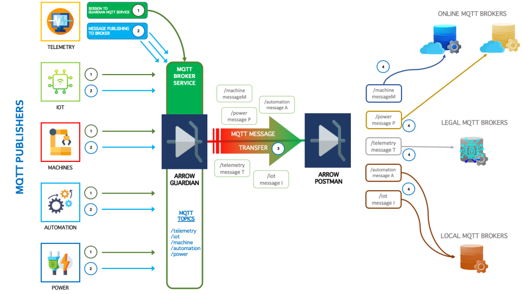
Any protocol promise of Arrow has no exception for MQTT protocol. Arrow pairs knows how to process MQTT packets and transfer based on the rule set administrators build.
Devices that generates MQTT based data are known as Publishers. They require a message collector to send the generated data, later to be collected by subscribers who are basically data consumers. Data used for monitoring, telemetry, reporting, legal issues and so on. Collectors in MQTT environments are called Brokers. Arrow Guardian is able to work as an MQTT broker, to collect data for MQTT topics from each receivers. Arrow provides a certificate based secure MQTT connection to each publisher. The certificate is built in, device specific and can be downloaded from Guardian user interface. As long as the MQTT service is licensed and enabled, any publisher can send their topic specific messages to Arrow.
Guardian does store any messages, and sends out to its sister Postman, from the secure, one-way fiber connection. Transfer of the data is part of the reception flow, so information has not to be kept waiting for any process, thus limiting transfer latency to minimum.
Postman acts as MQTT Publisher toward outer world. Upon Postman receiving the messages, it again sends out the data to an upstream broker defined from the user interface. It is possible to define a different broker for each topic. Each mapping creates a new publisher for the selected topic. Broker parameters including upstream security certificates can be configured from Postman user interface.
Below is a descriptive illustration of how Arrow MQTT flow works:
The command line interface is divided into many different modes, The commands available to you depend on which mode you are currently in. Enter a question mark (?) at the system prompt to obtain a list of commands available for each command mode. Table following describes the main command modes, how to access each one, the prompt you see in that mode, and how to exit the mode. The examples in the table use the hostname SWITCH. Table Command Mode Summary
SWITCH>Use this mode to: Perform basic tests. Display system information.
SWITCH#While in user EXEC mode, enter the enable command. Enter disable to exit. Use this mode to: Exec network utilities. Display module information. System management operation.
SWITCH(config)#While in Privileged mode, enter the configuration terminal command. Enter exit or end to return. Use this mode to: configure parameters that apply to the entire switch.
SWITCH(config-if)#While in global configuration mode, e interface command (with a specific interface). Enter exit or end to return. Use this mode to: configure parameters for the Ethernet ports.
SWITCH(config)#management vlan VLANID ip address IPADDR/MASKLEN gateway IPADDRSWITCH(config)#no management vlanManually assigning switch management IPv4 information.
SWITCH(config)#management vlan VLANID ip address dhcpSWITCH(config)#no management vlanConfiguring DHCP-Based IPv4 information autoconfiguration.
SWITCH(config)#management vlan VLANID ipv6 address IPV6ADDR/MASKLEN gateway IPV6ADDRSWITCH(config)#no management vlanManually assigning switch management IPv6 information.
SWITCH(config)#management vlan VLANID ipv6 address dhcpSWITCH(config)#no management vlanConfiguring DHCP-Based IPv6 information autoconfiguration.
SWITCH#show management summaryDisplay IP information.
Example 1: Manually assigning IPv4 information. The following examples shows how to configure management IPv4 address, The management VLAN is 1, the management IP is 192.168.64.200/24, and the gateway address is 192.168.64.1. Manually assigning IPv4 information:
SWITCH#configure terminalSWITCH(config)#management vlan 1 ip address 192.168.64.200/24 gateway 192.168.64.1Display IP information:
SWITCH#show management summaryManagement interface with Ipv4: Type: Static Vlan: 1 Ip address: 192.168.64.200/24 Gateway: 192.168.64.1 Backup/Restore Configuration
SWITCH#writeSave your entries in the configuration file.
SWITCH#copy default-config startup-configSWITCH#reloadRestore the system default configuration, which will take effect after the device restarts.
SWITCH#copy tftp tftp://A.B.C.D/FILE startup-configSWITCH#reloadA.B.C.D:remote tftp server ip address FILE:File name of configuration Import the remote configuration into the device through the tftp protocol, replacing the existing configuration. Take effect after device restart.
SWITCH#copy startup-config tftp tftp://A.B.C.D/FILEA.B.C.D:remote tftp server ip address FILE:File name of configuration Through the tftp protocol, the configuration is saved to the specified folder of the remote tftp server.
SWITCH#copy ftp ftp://A.B.C.D/FILE startup-configSWITCH#reloadA.B.C.D:remote tftp server ip address FILE:File name of configuration Import the remote configuration into the device through the ftp protocol, replacing the existing configuration. Take effect after device restart.
SWITCH#copy startup-config ftp ftp://A.B.C.D/FILEA.B.C.D:remote tftp server ip address FILE:File name of configuration Through the ftp protocol, the configuration is saved to the specified folder of the remote tftp server.
Example 1:Export the configuration to the folder specified by the remote tftp server, the file name is startup.conf. Environment construction: The remote PC starts the tftp server and selects the tftp current directory. The IP address of the remote PC is 192.168.64.1, and the management IP of the switch is configured as 192.168.64.100, and the remote PC can be pinged. Execute the configuration export command:
SWITCH#SWITCH# copy startup-config tftp tftp://192.168.64.1/startup.conf% Total % Received % Xferd Average Speed Time Time Time Current
100 1230 0 0 100 1230 0 151k –:–:– –:–:– –:–:– 240k 100 1230 0 0 100 1230 0 144k –:–:– –:–:– –:–:– 144k
In the test directory of the remote PC, you can view the newly created startup.conf file. Example 2:Import the configuration file startup.conf under the folder specified by the remote ftp server into the device. Environment construction: Start the ftp server on the remote PC, select the current directory of ftp, and place the startup.conf file. The IP address of the remote PC is 192.168.64.1, and the switch management IP is configured as 192.168.64.100, and the remote PC can be pinged. Execute the configuration import command:
SWITCH#SWITCH# #copy ftp ftp://192.168.64.1/startup.conf startup-configEnter Username:xxxxxx Enter Password:xxxxxx % Total % Received % Xferd Average Speed Time Time Time Current
100 973 100 973 0 0 42572 0 –:–:– –:–:– –:–:– 48650
After the configuration is imported, restart to take effect.
SWITCH# clear loggingSWITCH#reloadSystem warm restart.
SWITCH(config)# username NAME password LINESWITCH(config)# no username NAMEIf the user name does not exist, add a new user, if it exists, modify the user's password. By default, the device has its own user "admin" and password "admin", which supports password modification and deletion operations. The length of the user and password is 0-32 bytes. Password display is encrypted. Password characters are case sensitive. The delete operation does not support deleting the user itself; to delete an online user, the user must be kicked off the line first.
SWITCH(config)# web-server enable { all | http | https }SWITCH(config)# no web-server enableConfigure and enable WEB management. Default disabled state. Support IPv4 and IPv6.
SWITCH(config)# telnet-server enableSWITCH(config)# no telnet-server enableConfigure and enable telnet management. Default disabled state. Support IPv4 and IPv6.
SWITCH(config)# ssh-server enableSWITCH(config)# no ssh-server enableConfigure and enable SSH management. Default disabled state. Support IPv4 and IPv6.
SWITCH(config)# ip { telnet | ssh | http | https } access-class {<1-199> | <1300-2699> | ACLNAME}SWITCH(config)# no ip { telnet | ssh | http | https } access-classIPv4 ACL is applied to telnet, ssh, http, https and other services. Users who meet the ACL permit rules are allowed to access the device, otherwise users cannot access the device.
SWITCH(config)# ipv6 { telnet | ssh | http | https } access-class { ACLNAME }SWITCH(config)# no ipv6 { telnet | ssh | http | https } access-classIPv6 ACL is applied to telnet, ssh, http, https and other services. Users who meet the ACL permit rules are allowed to access the device, otherwise users cannot access the device.
SWITCH(config-line)# access-class {<1-199> | <1300-2699> | ACLNAME } inSWITCH(config-line)# no access-class {<1-199> | <1300-2699> | ACLNAME } inACL applied to vty. For telnet, ssh and other servers on vty. Users who meet the ACL permit rules are allowed to login by this line.
SWITCH(config-line)# transport input { telnet | ssh | all | none }SWITCH(config-line)# no transport inputConfigure services supported on vty. telnet: only supports telnet service. ssh: only supports ssh service. all: supports telnet and ssh services. none: No services are supported. Supports telnet and ssh services by default.
SWITCH# clear line { vty | console } LINEVty represents the remote login user. Console represents the serial port login user. LINE information can be viewed in the show users command. Kicking the user itself is not supported.
SWITCH#show userscon 0 admin 00:00:03 — vty 0 admin 00:00:11 192.168.64.1 Users display elements are as follows:
illustrate
console or vty
console: fixed 0 vty : 0-7
username
Time in idle state, if the timeout time is exceeded, the terminal automatically exits. Host Login user ip address
Case 1 : The device enables the telnet service. Only users with the IP address 192.168.64.100 are allowed to access the device through telnet, and other users are denied access.
SWITCH(config)#telnet-server enableSWITCH(config)#ip-access-list standard 1SWITCH(config-std-acl)#permit host 192.168.64.100SWITCH(config-std-acl)#exitSWITCH(config)#ip telnet access-class 1Case 2 : The device enables the telnet service, and the device only allows one user to log in to the device through telnet at the same time.
SWITCH(config)#telnet-server enableSWITCH(config)#line vty 1 7SWITCH(config-line)#transport input noneSWITCH(config)# hostname WORDThe name must consist of printable characters and the length cannot exceed 63 bytes. This configuration takes effect immediately.
SWITCH# upgrade firmware tftp://SERVER/FILENAMEYou need to build a TFTP server on the terminal, and ensure the two-way interconnection between the terminal and the device network. SERVER: TFTP server IP and the relative address of the server window and the firmware upgrade file. FILENAME: Firmware upgrade file. The firmware upgrade process will take 5-6 minutes, reboot the device to complete the firmware upgrade. Do not power off the device during the upgrade process. Example 1:The following examples shows firmware upgrade via tftp. Step 1: As shown in the figure below, SWITCH-A is the device to be upgraded, and the telnet function is enabled; USER-A is the host on the same network segment in the LAN, and USER-B is the management device in the LAN, both of which can log in to SWITCH-A by telnet.
Step 2: Select USER-B to perform the version upgrade operation. Open the TFTP server on USER-B and place the upgrade file xcat-release-3.2.0.bin in the Y:/workspace directory.TFTP server as shown in the figure below.
Step 3: USER-B telnet logs in to SWITCH-A and executes the upgrade command in privileged mode. Upgrade information as shown in the figure below.
Step 4: After the upgrade is over, select "y" to restart the device to complete the upgrade, select "n" to continue running the device, and the upgrade operation will be completed after restart.
SWITCH# clock set HH:MM:SS DAY MON YEARSetting the system clock. For example:Clock set 15:30:00 1 october 2017.
SWITCH(config)# ntp server {A.B.C.D | ipv6 X.X::X.X }Configure the IP address of the NTP server (domain name configuration is not supported). After the configuration is complete, if the device and the server are connected to the network, the device will automatically synchronize the time information from the server. It takes about 4-8 minutes to complete the time synchronization for the first time.
SWITCH(config)# clock timezone ZONEConfigure the system time zone. The default timezone is UTC. Supports standard time zone configuration, such as Shanghai time zone keyword "Shanghai", Hong Kong time zone keyword "Hong_Kong", etc.
SWITCH# show clockDisplay system clock.
SWITCH# show ntp statusDisplay ntp status.
Imported from the Connexite public documentation portal. Original hub: https://support.connexite.co.uk/landing.html.
Documentation for Synapse network switches: command-line and Web UI references.
Networking › Switching › Edge › Synapse
Sections below mirror the table of contents from the source site.
The command line interface is divided into many different modes, The commands available to you depend on which mode you are currently in. Enter a question mark (?) at the system prompt to obtain a list of commands available for each command mode. Table following describes the main command modes, how to access each one, the prompt you see in that mode, and how to exit the mode. The examples in the table use the hostname SWITCH. Table Command Mode Summary
SWITCH>Use this mode to: Perform basic tests. Display system information.
SWITCH#While in user EXEC mode, enter the enable command. Enter disable to exit. Use this mode to: Exec network utilities. Display module information. System management operation.
SWITCH(config)#While in Privileged mode, enter the configuration terminal command. Enter exit or end to return. Use this mode to: configure parameters that apply to the entire switch.
SWITCH(config-if)#While in global configuration mode, e interface command (with a specific interface). Enter exit or end to return. Use this mode to: configure parameters for the Ethernet ports.
SWITCH(config)#management vlan VLANID ip address IPADDR/MASKLEN gateway IPADDRSWITCH(config)#no management vlanManually assigning switch management IPv4 information.
SWITCH(config)#management vlan VLANID ip address dhcpSWITCH(config)#no management vlanConfiguring DHCP-Based IPv4 information autoconfiguration.
SWITCH(config)#management vlan VLANID ipv6 address IPV6ADDR/MASKLEN gateway IPV6ADDRSWITCH(config)#no management vlanManually assigning switch management IPv6 information.
SWITCH(config)#management vlan VLANID ipv6 address dhcpSWITCH(config)#no management vlanConfiguring DHCP-Based IPv6 information autoconfiguration.
SWITCH#show management summaryDisplay IP information.
Example 1: Manually assigning IPv4 information. The following examples shows how to configure management IPv4 address, The management VLAN is 1, the management IP is 192.168.64.200/24, and the gateway address is 192.168.64.1. Manually assigning IPv4 information:
SWITCH#configure terminalSWITCH(config)#management vlan 1 ip address 192.168.64.200/24 gateway 192.168.64.1Display IP information:
SWITCH#show management summaryManagement interface with Ipv4: Type: Static Vlan: 1 Ip address: 192.168.64.200/24 Gateway: 192.168.64.1 Backup/Restore Configuration
SWITCH#writeSave your entries in the configuration file.
SWITCH#copy default-config startup-configSWITCH#reloadRestore the system default configuration, which will take effect after the device restarts.
SWITCH#copy tftp tftp://A.B.C.D/FILE startup-configSWITCH#reloadA.B.C.D:remote tftp server ip address FILE:File name of configuration Import the remote configuration into the device through the tftp protocol, replacing the existing configuration. Take effect after device restart.
SWITCH#copy startup-config tftp tftp://A.B.C.D/FILEA.B.C.D:remote tftp server ip address FILE:File name of configuration Through the tftp protocol, the configuration is saved to the specified folder of the remote tftp server.
SWITCH#copy ftp ftp://A.B.C.D/FILE startup-configSWITCH#reloadA.B.C.D:remote tftp server ip address FILE:File name of configuration Import the remote configuration into the device through the ftp protocol, replacing the existing configuration. Take effect after device restart.
SWITCH#copy startup-config ftp ftp://A.B.C.D/FILEA.B.C.D:remote tftp server ip address FILE:File name of configuration Through the ftp protocol, the configuration is saved to the specified folder of the remote tftp server.
Example 1:Export the configuration to the folder specified by the remote tftp server, the file name is startup.conf. Environment construction: The remote PC starts the tftp server and selects the tftp current directory. The IP address of the remote PC is 192.168.64.1, and the management IP of the switch is configured as 192.168.64.100, and the remote PC can be pinged. Execute the configuration export command:
SWITCH#SWITCH# copy startup-config tftp tftp://192.168.64.1/startup.conf% Total % Received % Xferd Average Speed Time Time Time Current
100 1230 0 0 100 1230 0 151k –:–:– –:–:– –:–:– 240k 100 1230 0 0 100 1230 0 144k –:–:– –:–:– –:–:– 144k
In the test directory of the remote PC, you can view the newly created startup.conf file. Example 2:Import the configuration file startup.conf under the folder specified by the remote ftp server into the device. Environment construction: Start the ftp server on the remote PC, select the current directory of ftp, and place the startup.conf file. The IP address of the remote PC is 192.168.64.1, and the switch management IP is configured as 192.168.64.100, and the remote PC can be pinged. Execute the configuration import command:
SWITCH#SWITCH# #copy ftp ftp://192.168.64.1/startup.conf startup-configEnter Username:xxxxxx Enter Password:xxxxxx % Total % Received % Xferd Average Speed Time Time Time Current
100 973 100 973 0 0 42572 0 –:–:– –:–:– –:–:– 48650
After the configuration is imported, restart to take effect.
SWITCH# clear loggingSWITCH#reloadSystem warm restart.
SWITCH(config)# username NAME password LINESWITCH(config)# no username NAMEIf the user name does not exist, add a new user, if it exists, modify the user's password. By default, the device has its own user "admin" and password "admin", which supports password modification and deletion operations. The length of the user and password is 0-32 bytes. Password display is encrypted. Password characters are case sensitive. The delete operation does not support deleting the user itself; to delete an online user, the user must be kicked off the line first.
SWITCH(config)# web-server enable { all | http | https }SWITCH(config)# no web-server enableConfigure and enable WEB management. Default disabled state. Support IPv4 and IPv6.
SWITCH(config)# telnet-server enableSWITCH(config)# no telnet-server enableConfigure and enable telnet management. Default disabled state. Support IPv4 and IPv6.
SWITCH(config)# ssh-server enableSWITCH(config)# no ssh-server enableConfigure and enable SSH management. Default disabled state. Support IPv4 and IPv6.
SWITCH(config)# ip { telnet | ssh | http | https } access-class {<1-199> | <1300-2699> | ACLNAME}SWITCH(config)# no ip { telnet | ssh | http | https } access-classIPv4 ACL is applied to telnet, ssh, http, https and other services. Users who meet the ACL permit rules are allowed to access the device, otherwise users cannot access the device.
SWITCH(config)# ipv6 { telnet | ssh | http | https } access-class { ACLNAME }SWITCH(config)# no ipv6 { telnet | ssh | http | https } access-classIPv6 ACL is applied to telnet, ssh, http, https and other services. Users who meet the ACL permit rules are allowed to access the device, otherwise users cannot access the device.
SWITCH(config-line)# access-class {<1-199> | <1300-2699> | ACLNAME } inSWITCH(config-line)# no access-class {<1-199> | <1300-2699> | ACLNAME } inACL applied to vty. For telnet, ssh and other servers on vty. Users who meet the ACL permit rules are allowed to login by this line.
SWITCH(config-line)# transport input { telnet | ssh | all | none }SWITCH(config-line)# no transport inputConfigure services supported on vty. telnet: only supports telnet service. ssh: only supports ssh service. all: supports telnet and ssh services. none: No services are supported. Supports telnet and ssh services by default.
SWITCH# clear line { vty | console } LINEVty represents the remote login user. Console represents the serial port login user. LINE information can be viewed in the show users command. Kicking the user itself is not supported.
SWITCH#show userscon 0 admin 00:00:03 — vty 0 admin 00:00:11 192.168.64.1 Users display elements are as follows:
illustrate
console or vty
console: fixed 0 vty : 0-7
username
Time in idle state, if the timeout time is exceeded, the terminal automatically exits. Host Login user ip address
Case 1 : The device enables the telnet service. Only users with the IP address 192.168.64.100 are allowed to access the device through telnet, and other users are denied access.
SWITCH(config)#telnet-server enableSWITCH(config)#ip-access-list standard 1SWITCH(config-std-acl)#permit host 192.168.64.100SWITCH(config-std-acl)#exitSWITCH(config)#ip telnet access-class 1Case 2 : The device enables the telnet service, and the device only allows one user to log in to the device through telnet at the same time.
SWITCH(config)#telnet-server enableSWITCH(config)#line vty 1 7SWITCH(config-line)#transport input noneSWITCH(config)# hostname WORDThe name must consist of printable characters and the length cannot exceed 63 bytes. This configuration takes effect immediately.
SWITCH# upgrade firmware tftp://SERVER/FILENAMEYou need to build a TFTP server on the terminal, and ensure the two-way interconnection between the terminal and the device network. SERVER: TFTP server IP and the relative address of the server window and the firmware upgrade file. FILENAME: Firmware upgrade file. The firmware upgrade process will take 5-6 minutes, reboot the device to complete the firmware upgrade. Do not power off the device during the upgrade process. Example 1:The following examples shows firmware upgrade via tftp. Step 1: As shown in the figure below, SWITCH-A is the device to be upgraded, and the telnet function is enabled; USER-A is the host on the same network segment in the LAN, and USER-B is the management device in the LAN, both of which can log in to SWITCH-A by telnet.
Step 2: Select USER-B to perform the version upgrade operation. Open the TFTP server on USER-B and place the upgrade file xcat-release-3.2.0.bin in the Y:/workspace directory.TFTP server as shown in the figure below.
Step 3: USER-B telnet logs in to SWITCH-A and executes the upgrade command in privileged mode. Upgrade information as shown in the figure below.
Step 4: After the upgrade is over, select "y" to restart the device to complete the upgrade, select "n" to continue running the device, and the upgrade operation will be completed after restart.
SWITCH# clock set HH:MM:SS DAY MON YEARSetting the system clock. For example:Clock set 15:30:00 1 october 2017.
SWITCH(config)# ntp server {A.B.C.D | ipv6 X.X::X.X }Configure the IP address of the NTP server (domain name configuration is not supported). After the configuration is complete, if the device and the server are connected to the network, the device will automatically synchronize the time information from the server. It takes about 4-8 minutes to complete the time synchronization for the first time.
SWITCH(config)# clock timezone ZONEConfigure the system time zone. The default timezone is UTC. Supports standard time zone configuration, such as Shanghai time zone keyword "Shanghai", Hong Kong time zone keyword "Hong_Kong", etc.
SWITCH# show clockDisplay system clock.
SWITCH# show ntp statusDisplay ntp status.
The interfaces of switch can be divided into the following two categories: Layer 2 interfaces and Layer 3 interfaces. L2 interface,Including common physical ports (Switch Port) and aggregate ports (Port Channel). Switch Port consists of a single physical port on the device and only support Layer 2 switching. The port can be an Access Port, Hybrid Port or a Trunk Port. Port Channel is formed by the aggregation of multiple physical member ports. We can bundle multiple physical links together to form a simple logical link, which we call an aggregate port. For Layer 2 switching, the aggregation port can superimpose the bandwidth of multiple ports to expand the link bandwidth. L3 interface,Here mainly refers to the SVI port. SVI is a switching virtual interface, a logical interface used to implement Layer 3 switching. SVI can be used as the local management interface, through which the administrator can manage the device. You can create an SVI with the interface vlan interface configuration command, and then assign an IP address to the SVI to establish routing between VLANs.
SWITCH(config)# interface IFNAME_RANGESpecify the range of interfaces to be configured, and enter interface-range configuration mode. When there are multiple range combinations, separate them with ',' without spaces. For example, the command interface range gigabitEthernet 0/1-4, gigabitEthernet 0/9-12 is a valid range. You can use the interface range command to configure up to five port ranges; Each interface-range must consist of the same port type.
SWITCH(config-if)# description DESCAdd a description (up to 80 characters) for an interface.
SWITCH(config-if)# shutdownSWITCH(config-if)# no shutdownShut down an interface.
SWITCH(config-if)# speed {10 | 100 | 1000 | auto}SWITCH(config-if)# no speedEnter auto to enable the interface to autonegotiate speed with the connected device. If you use the 10, 100, or the 1000 keywords with the auto keyword, the port autonegotiates only at the specified speeds;
SWITCH(config-if)# duplex {auto | full | half}SWITCH(config-if)# no duplexEnable half-duplex mode (for interfaces operating only at 10 or 100 Mbps). You cannot configure half-duplex mode for interfaces operating at 1000 Mbps Attention: ✦ When both speed and duplex exit auto mode, port auto-negotiation is disabled. Flow control enables connected Ethernet ports to control traffic rates during congestion by allowing congested nodes to pause link operation at the other end. If one port experiences congestion and cannot receive any more traffic, it notifies the other port by sending a pause frame to stop sending until the condition clears. Upon receipt of a pause frame, the sending device stops sending any data packets, which prevents any loss of data packets during the congestion period.
SWITCH(config-if)# flowcontrol {on | off }Configure the flow control mode for the port. on: The port cannot send pause frames but can operate with an attached device that is required to or can send pause frames; the port can receive pause frames. off: Flow control does not operate in either direction. In case of congestion, no indication is given to the link partner, and no pause frames are sent or received by either device. When a port performs high-throughput data exchange, it may encounter a frame larger than the Ethernet standard frame length, which is called a jumbo frame. The user can control the maximum frame length that the port is allowed to send and receive by setting the MTU of the port. Frames received or forwarded by the port, if the length exceeds the set MTU, will be discarded. Due to chip limitations, the MTU value only supports even numbers. If the user configures an odd number, the device will auto-align to even. For example, if the MTU is configured as 127, it actually works as 128.
SWITCH(config-if)# mtu LENGTHSWITCH(config-if)# no mtuChange the MTU size for the interface on the switch. The range is 46 to 10222 bytes; the default is 1500 bytes.
SWITCH(config-if)# port mode {sgmii | 2500BASE-X | 1000BASE-X | 10G}SWITCH(config-if)# no port mode1000BASE-X:The port operate at 1000Mbps, full-duplex only. Sgmii: Enables connection to external copper transceivers. 2500BASE-X: The port operate at 2.5G, full-duplex only. 10G: The port operate at 2.5G, full-duplex only. If a port can be configured both fiber and copper medium types, you can only use one of them. Once the medium type is determined, configure the properties of the port, such as duplex, flow control, and rate, which all refer to the properties of the currently selected type of port.
SWITCH(config-if)# medium {copper | fiber | auto [prefer (copper | fiber)]}SWITCH(config-if)# no mediumConfiguring interface medium type. Default is auto mode,prefer copper. Copper:Indicates the choice of copper medium type. Fiber:Indicates the choice of fiber medium type. Auto:Indicates the adaptive port media type,Determine whether it is an copper or fiber port based on the access medium, prefer copper. Auto prefer copper:Indicates the adaptive port media type,When both fiber and copper are connected, prefer the copper port. Auto prefer fiber:Indicates the adaptive port media type,When both fiber and copper are connected, prefer the fiber port. No operation restores the media type to copper. In some situations, you need to prevent Layer 2 (L2) connectivity between end devices on a switch, you can use the isolate function. When some ports are set as isolated ports, the isolated ports cannot communicate with each other, the isolated port and the non-isolated port can communicate normally, and the non-isolated port and the non-isolated port can communicate normally.
SWITCH(config-if)#switchport isolateSWITCH(config-if)# no switchport isolateSetting the port as an isolated port.
SWITCH(config-if)# autoneg onSWITCH(config-if)# no autonegConfigure port auto-negotiation on and off. Only applicable to 1000M optical port, If this command is configured on other ports, it prompts failure. Default is on. By show interface brief command, You can view the auto-negotiation status of the link up ports.
SWITCH#SWITCH#configure terminalEnter configuration commands, one per line. End with CNTL/Z.
SWITCH(config)#interface gigabitEthernet0/1SWITCH(config-if)#SWITCH(config-if)#description TEST_ASWITCH(config-if)#no shutdownSWITCH(config-if)#speed 100SWITCH(config-if)#duplex fullSWITCH(config-if)#flowcontrol onSWITCH(config-if)#mtu 1024SWITCH#show interface brief——————————————————————————–
Interface Ch # ——————————————————————————– GiE0/1 ETH down none — — — — — GiE0/2 ETH up none 1000M FULL OFF ON — GiE0/3 ETH down none — — — — — GiE0/4 ETH down none — — — — — GiE0/5 ETH down none — — — — — GiE0/6 ETH down none — — — — — GiE0/7 ETH down none — — — — — GiE0/8 ETH up none 100M FULL OFF ON — GiE0/9 ETH down none — — — — — GiE0/10 ETH down none — — — — — GiE0/11 ETH down none — — — — — GiE0/12 ETH down none — — — — —
SWITCH#show interface gigabitethernet0/1Interface gigabitethernet0/1 Hardware is eth current hw addr: 0050.4c82.89a0 Physical:0050.4c82.89a0
Description: test_a Index 1 metric 0 mtu 1024 speed-unknown duplex-unknown flowcontrol-unknown
<up> vrf binding: not bound Bandwidth -8 Input packets 0677, bytes 072690, Multicast packets 0327 broadcast packets 0350 fcs error 00 undersizeerrors 00 oversizeerrors 00 Output packets 00, bytes 00, Multicast packets 00 broadcast packets 00
SWITCH#show interface gigabitEthernet0/1 countersInterface gigabitEthernet16/1 Good Octets Tx : 1914949 Good Octets Rx : 0 Bad Octets Rx : 0 Mac Tx Err Pkts : 0 Good Packets Tx : 1913 Good Packets Rx : 0 Bad Packets Rx : 0 Broadcast Packet Tx : 24 Broadcast Packets Rx : 0 Multicast Packet Tx : 55 Multicast Packets Rx : 0 pkts_64_octets : 285 pkts_65_127_octets : 263 pkts_128_255_octets : 42 pkts_256_511_octets : 36 pkts_512_1023_octets : 91 pkts_1024_max_octets : 1196 Excessive Collisions : 0 UnRecg MAC Cntl Pkts Rx : 0 Flow Ctrl Pkts Sent : 0 Flow Ctrl Pkts Recvd : 0 Drop Events : 0 Undersized Pkts Recvd : 0 Fragments Recvd : 0 Oversized Pkts Recvd : 0 Jabber Pkts Recvd : 0 mac_rcv_error : 0 Bad CRC : 0 Collisions : 0 Late Collisions : 0 Bad Flow Ctrl Recv : 0
SWITCH#show switchport isolateinterface config GiE0/1 isolated GiE0/2 normal GiE0/3 normal GiE0/4 normal GiE0/5 normal GiE0/6 normal GiE0/7 normal GiE0/8 normal GiE0/9 normal GiE0/10 normal
Storm control prevents traffic on a LAN from being disrupted by a broadcast, multicast, or unicast storm on one of the physical interfaces. A LAN storm occurs when packets flood the LAN, creating excessive traffic and degrading network performance. Errors in the protocol-stack implementation, mistakes in network configurations, or users issuing a denial-of-service attack can cause a storm.。 Storm control uses bandwidth as a percentage of the total available bandwidth of the port that can be used by the broadcast, multicast, or unicast traffic, to measure traffic activity. because of hardware limitations and the way in which packets of different sizes are counted, threshold percentages are approximations.
SWITCH(config-if)#storm-control {broadcast | multicast | unicast | all | unicast-broadcast | multicast-broadcast} level LINESWITCH(config-if)#no storm-controlConfigure broadcast, multicast, or unicast storm control. By default, storm control is disabled. If you set the threshold to the maximum value (100 percent), no limit is placed on the traffic. If you set the threshold to 0.0, traffic on that port is blocked. The range is 0.00 to 100.00. Support adaptive port rate change. Unicast only containing unknown unicast packets.
Example 1:Configure the unknown multicast storm control on port gigabitEthernet0/1 to 10% of the total bandwidth. Step 1: Specify the interface gigabitEthernet0/1 to be configured, and enter interface configuration mode.
SWITCH#SWITCH#configure terminalEnter configuration commands, one per line. End with CNTL/Z.
SWITCH(config)#interface gigabitEthernet0/1SWITCH(config-if)#Step 2: Configure the unknown multicast storm control on port gigabitEthernet0/1 to 10%.
SWITCH(config-if)#storm-control multicast level 10SWITCH#show storm-controlGiE0/1 100.00% 10.00% 100.00% GiE0/2 100.00% 100.00% 100.00% GiE0/3 100.00% 100.00% 100.00% GiE0/4 100.00% 100.00% 100.00% GiE0/5 100.00% 100.00% 100.00% GiE0/6 100.00% 100.00% 100.00% GiE0/7 100.00% 100.00% 100.00% GiE0/8 100.00% 100.00% 100.00% GiE0/9 100.00% 100.00% 100.00% GiE0/10 100.00% 100.00% 100.00% GiE0/11 100.00% 100.00% 100.00% GiE0/12 100.00% 100.00% 100.00%
You can analyze network traffic passing through ports by using SPAN(Local Switched Port Analyzer)to send a copy of the traffic to another port on the switch that has been connected to a network analyzer or other monitoring or security device. SPAN copies traffic received or sent (or both) on source ports to a destination port for analysis. SPAN does not affect the switching of network traffic on the source ports. You must dedicate the destination port for SPAN use. Except for traffic that is required for the SPAN session, destination ports do not receive or forward traffic.
SPAN supports a session entirely within one switch. all source ports and destination ports are in the same switch. SPAN sessions allow you to monitor traffic on one or more ports, and send the monitored traffic to only one destination port. A SPAN session is an association of a destination port with source ports, all on a single network device.
SWITCH(config)#monitor session SESSION-IDSWITCH(config)#no monitor session SESSION-IDCreate a SPAN session. For session_number, the range is 1 to 7
SWITCH(config-monitor)#description DESCAdd a description (up to 64 characters) for an interface
SWITCH(config-monitor)#source interface IFNAME {both | rx | tx}SWITCH(config-monitor)#no source interface IFNAME {both | rx | tx}Specify the SPAN session and the source port.
SWITCH(config-monitor)#destination interface IFNAMESWITCH(config-monitor)#no destination interface IFNAMESpecify the SPAN session and the destination port.
Example 1: This example shows how to create SPAN session, and configure session source interfaces and destination interface. Step 1: Create session.
SWITCH#configure terminalEnter configuration commands, one per line. End with CNTL/Z.
SWITCH(config)#monitor session 1SWITCH(config-monitor)#Step 2: Configuring session description.
SWITCH(config-monitor)#description TRAFFIC_MONITORStep 3: Configuring session source interfaces.
SWITCH(config-monitor)#source interface gigabitEthernet0/1 rxSWITCH(config-monitor)#source interface gigabitEthernet0/2 bothStep 4: Configuring session destination interface.
SWITCH(config-monitor)#destination interface gigabitEthernet0/8SWITCH#show monitor session 1session 1 ————— description : TRAFFIC_MONITOR type : local source intf : tx : gigabitEthernet0/2 rx : gigabitEthernet0/1 gigabitEthernet0/2 both : gigabitEthernet0/2 source VLANs : rx : destination ports : gigabitEthernet0/8 Legend: f = forwarding enabled, l = learning enabled
Port aggregation provides fault-tolerant high-speed links between switches, routers, and servers. You can use it to increase the bandwidth between the wiring closets and the data center, and you can deploy it anywhere in the network where bottlenecks are likely to occur. Port aggregation provides automatic recovery for the loss of a link by redistributing the load across the remaining links. If a link fails, port aggregation redirects traffic from the failed link to the remaining links in the channel without intervention. Port aggregation consists of individual Fast Ethernet or Gigabit Ethernet links bundled into a single logical link called channel, as shown in Figure below.
Each Channel can consist of up to eight compatibly configured Ethernet ports. All ports in each Channel must be configured as Layer 2 ports. The number of Channels is limited to 12. You can configure an Channel in one of these modes: Manual(Static), Active(LACP), or Passive(LACP).
LACP (Link Aggregation Control Protocol) based on the IEEE802.3ad standard is a dynamic link aggregation protocol. If a port enables the LACP, the port will send LACPDU message to announce its system priority, system MAC, port priority, port number and operation key, etc. After the connected device receives the LACP message from the peer end, it compares the system priorities of the two ends according to the system ID in the message. On the side with the higher system ID priority, the ports in the aggregation group are set to be in the aggregation state according to the order of port ID priority from high to low, and the updated LACP message is sent out. It will also set the corresponding port to the aggregation state, so that the two sides can reach the same agreement when the port exits or joins the aggregation group. After the LACP member interface link is bound, periodic LACP packet exchange will be carried out. When no LACP packet is received for a period of time, it is considered that the packet reception timed out, the member interface link is unbound, and the port is in a state of non-forwarding again. There are two modes of timeout here: long timeout mode and short timeout mode. In the long timeout mode, the port sends a packet every 30 seconds. If it does not receive a packet from the peer for 90 seconds, it will be in a packet receiving timeout.;In the short timeout mode, the port sends a packet every 1 second. If it does not receive a packet from the peer for 3 seconds, it is in the packet receiving timeout.
As shown Figure, switch A and switch B are connected together through 3 ports. We set the system priority of switch A to 61440, and set the system priority of switch B to 4096. Enable LACP link aggregation on the three directly connected ports of switches A and B. After receiving the LACP message from the peer, switch B finds that its system ID has a higher priority (switch B has a higher system priority than switch A), so it follows the order of port ID priority (in the case of the same port priority) , in the order of port numbers from small to large) set ports 4, 5, and 6 to be in the aggregation state. After switch A receives the updated LACP packet from switch B, it finds that the system ID of the peer end has a higher priority, and set the ports 1, 2, and 3 to the aggregation state.
SWITCH(config-if)#channel-group ID mode manualSWITCH(config-if)#channel-group ID mode {active | passive}SWITCH(config-if)#no channel-groupAssign the port to a channel group, and specify the mode. For ID, the range is 1 to 12.
✦ When the first port is added to the aggregation port, a PO port is actively created, and the default attribute of the PO port is the first port attribute. ✦ For Layer 2 Channels: Ports with different native VLANs cannot form an EtherChannel.
SWITCH(config)#lacp system-priority SYSTEM-PRIORITYSWITCH(config)#no lacp system-priorityThe system priority range is 1 to 65535, the default value is 32768. All dynamic link groups of a device can only have one LACP system priority. Modifying this value will affect all aggregation groups on the switch.
SWITCH(config-if)#lacp port-priority PORT-PRIORITYSWITCH(config-if)#no lacp port-priorityThe interface priority range is 1 to 65535, the default value is 32768.
SWITCH(config-if)#lacp timeout {long | short}SWITCH(config-if)#no lacp timeoutIn long mode, the interval for sending LACP protocol packets is 30S, and the timeout is 90S. In short mode, the interval for sending LACP protocol packets is 1S, and the timeout is 3S. Default is in long mode.
SWITCH(config)#port-channel load-balance {dst-ip | dst-mac | dst-port | src-dst-ip | src-dst-mac | src-dst-port | src-ip | src-mac | src-port}SWITCH(config)#no port-channel load-balanceConfigure an Channel load-balancing method. The default is src-mac. Select one of these load-distribution methods: • dst-ip: Load distribution is based on the destination IP address. dst-mac: Load distribution is based on the destination MAC address of the incoming packet. Dist-port: Load distribution is based on the destination L4-port of the incoming packet src-dst-ip: Load distribution is based on the source-and-destination IP address. src-dst-mac: Load distribution is based on the source-and-destination MAC address. src-dst-port: Load distribution is based on the source-and-destination L4-port of the incoming packet. src-ip: Load distribution is based on the source IP address. src-mac: Load distribution is based on the source-MAC address of the incoming packet.
Example 1: This example shows how to assign the ports to a channel, and set load-balance method.
SWITCH(config)#interface gigabitEthernet0/5SWITCH(config-if)#channel-group 1 mode manualSWITCH(config-if)#exitSWITCH(config)#interface gigabitEthernet0/6SWITCH(config-if)#channel-group 1 mode manualSWITCH(config-if)#exitSWITCH(config)#port-channel load-balance src-ipSWITCH#show port-channelLoad balance: Source and Destination Mac address Interface po3 Type: static Member: gigabitEthernet0/18 link down Disable Interface po8 Type: LACP Member: gigabitEthernet0/19 link up Enable gigabitEthernet0/17 link up Enable
SWITCH#show port-channel 8Interface po8 Type: LACP Member: gigabitEthernet0/19 link up Enable gigabitEthernet0/17 link up Enable
SWITCH#show port-channel load-balanceSWITCH#show lacp summary% Aggregator po8 1008 % Aggregator Type: Layer2 % Admin Key: 0008 – Oper Key 0008 % Link: gigabitEthernet0/17 (17) sync: 1 status: Bundled % Link: gigabitEthernet0/19 (19) sync: 1 status: Bundled
SWITCH#show lacp detail% Aggregator po8 1008 % Aggregator Type: Layer2 % Mac address: 74:b9:eb:ee:25:46 % Admin Key: 0008 – Oper Key 0008 % Actor LAG ID- 0x8000,74-b9-eb-ee-25-46,0×0008 % Receive link count: 2 – Transmit link count: 2 % Individual: 0 – Ready: 1 % Partner LAG ID- 0x8000,00-01-a0-00-10-10,0×0032 % Link: gigabitEthernet0/17 (17) sync: 1 status: Bundled % Link: gigabitEthernet0/19 (19) sync: 1 status: Bundled
SWITCH#show lacp 8% Aggregator po8 1008 Admin Key: 0008 – Oper Key 0008 % Partner LAG ID: 0x8000,00-01-a0-00-10-10,0×0032 % Partner Oper Key 0050
SWITCH#show lacp sys-id% System 8000,74-b9-eb-ee-25-46
SWITCH#show lacp port gigabitEthernet0/19% LACP link info: gigabitEthernet0/19 – 19 % LAG ID: 0x8000,74-b9-eb-ee-25-46,0×0008 % Partner oper LAG ID: 0x8000,00-01-a0-00-10-10,0×0032 % Actor Port priority: 0x8000 (32768) % Admin key: 0x0008 (8) Oper key: 0x0008 (8) % Physical admin key:(1) % Receive machine state : Current % Periodic Transmission machine state : Slow periodic % Mux machine state : Collecting/Distributing % Oper state: ACT:1 TIM:0 AGG:1 SYN:1 COL:1 DIS:1 DEF:0 EXP:0 % Partner oper state: ACT:1 TIM:0 AGG:1 SYN:1 COL:1 DIS:1 DEF:0 EXP:0 % Partner link info: admin port 0 % Partner oper port: 20 % Partner admin LAG ID: 0x0000-00:00:00:00:0000 % Admin state: ACT:1 TIM:0 AGG:1 SYN:0 COL:0 DIS:0 DEF:1 EXP:0 % Partner admin state: ACT:0 TIM:0 AGG:1 SYN:0 COL:0 DIS:0 DEF:1 EXP:0 % Partner system priority – admin:0x0000 – oper:0x8000 % Partner port priority – admin:0x0000 – oper:0x8000 % Aggregator ID: 1008
SWITCH#show int po8Interface po8 Hardware is AGG Current HW addr: 74b9.ebee.2546 Logical:(not set)
interface configure: medium-fiber mtu 1526 speed-auto duplex-auto flowcontrol-off autonego-off interface status: link-up bandwidth-2g Aggregate Members:(LACP) gigabitEthernet0/19 link up Enable gigabitEthernet0/17 link up Enable input packets: Good Octets Rx : 18986 Good Packets Rx : 104 Broadcast Packets Rx : 0 Multicast Packets Rx : 104 ouput packets: Good Octets Tx : 38529 Good Packets Tx : 359 Broadcast Packet Tx : 4 Multicast Packet Tx : 355 un-normal packets: Drop Events : 0 Undersized Pkts Recvd : 0 Oversized Pkts Recvd : 0 Bad CRC : 0
Power over Ethernet (PoE) is a technology that transmits both electrical power and network data over an ethernet cable. With PoE, each Ethernet interface of LAN switches can supply power to devices like VoIP phones, IP cameras or security cameras, and wireless access points (AP), As shown in the figure below.
The PoE device like LAN switches that are supplying power is called Power Sourcing Equipment (PSE). The power that is supplying is in Direct Current (DC) form. PoE (Power over Ethernet) Standards: PoE : IEEE 802.3af standard that supplies up to 15 watts of DC power from PSE and 12.95 watts from PD due to losses on an ethernet cable. It uses two pairs of wires like CAT3 or CAT5 cables as a medium. PoE+: IEEE 802.3at standard that supplies power up to 30 watts of DC power from PSE and 25.5 watts from PD due to losses on an ethernet cable. It is also using two pairs of wires like CAT5 or higher as a medium. UPoE(Universal PoE): IEEE 802.3bt standard that supplies power up to 60 watts of DC power from PSE and 51 watts from PD due to losses on an ethernet cable. It uses four pairs of wire as a medium. UPoE+(Universal PoE +): IEEE 802.3bt standard that supplies power up to 100 watts of DC power from PSE and 71.3 watts from PD due to losses on an ethernet cable. It is also using four pairs of ethernet cabling as a medium.
SWITCH(config)#poe powersupply POWERSWITCH(config)#no poe powersupplyThe default power calculation method: the product of the number of PoE power supply ports and the single port 15.4W. If the configured power is less than the current device power consumption, power off the PD device on the port with the lower priority, and the port priority is a higher priority with a smaller port ID.
SWITCH (config-if)#poe enableSWITCH (config-if)#no poe enableDefault port power supply enabled.
SWITCH (config)#poe legacySWITCH (config)#no poe legacyUsing this command on a port that is not connected to a PD device may cause the peer device to be burned by wrong power-on. Please make sure that the port uses this command when connecting to a PD device.
Example 1: Enable interface gigabitEthernet0/1 powersupply.
SWITCH(config)#interface gigabitEthernet0/1SWITCH(config-if)#poe enableSWITCH#show poe powersupplyPower supply : 123.2W Power consume : 44.1W Power management : energy-saving Disconnect mode : DC Powered ports : 2
SWITCH#show poe interfacesInterface enable status reason class icut(mA) power(W) —————————————————————- GiE0/1 YES OFF short 4 — — GiE0/2 YES OFF — – — — GiE0/3 YES OFF — – — — GiE0/4 YES OFF — – — — GiE0/5 YES OFF — – — — GiE0/6 YES ON — 4 270.2 14.0 GiE0/7 YES OFF — – — — GiE0/8 YES OFF — – — —
During the operation of the device, various status changes will occur, such as link status UP, DOWN, etc., and some events such as processing exceptions will also be encountered. The syslog provides a series of services. When the status changes or an event occurs, fixed-format messages will be automatically generated, and these messages will be recorded on the device log file. It can be displayed on the console port and remote login terminal, and can also be sent to 1-3 groups of log servers on the network for administrators to analyze network conditions and locate problems. In order to facilitate administrators to read and manage log messages, these log messages can be classified according to the priority of the log information.
Configure Console Log Level
SWITCH(config)# logging console {| <0-7>}SWITCH(config)# no logging consoleDefault level is 6 When executing the no command, the log will not be output on the console. Execute logging console, no level parameters, configured as default level 6
SWITCH(config) #logging monitor {| < 0-7>}SWITCH(config)# no logging monitorDefault level is 6 When executing the no command, the log will not be output Execute logging monitor, no level parameters, configured to the default level 6
SWITCH# terminal monitorSWITCH# terminal no monitorBy default, the terminal does not output log When executing the no command, the terminal does not output log
SWITCH(config)# logging server {| second | third} {A.B.C.D | ipv6 XX::XX } udp-port <1-65535>SWITCH(config)# no logging server {| second | third}Supports up to 3 remote server configurations Support remote server UDP protocol port configuration, range <1-65535> When no UDP protocol port parameters are configured, the default port number is 514
SWITCH(config) #logging trap {| < 0-7>}SWITCH(config)# no logging trapDefault level is 6 When executing the no command, no logs will be sent to the server. Execute logging trap , no level parameters, configured as default level 6
SWITCH(config) #logging rate-limit interval <1-30> burst <1-1000>SWITCH(config)#no logging rate-limitInterval is the time range, the default is 6, the range is <1-30>, the unit is seconds burst is the maximum number of logs that can be sent within the time range, the default is 60, the range is <1-1000> By default, up to 60 sys logs can be sent to the server every 6 seconds Configure the Logging Buffer
SWITCH(config) #logging buffer <64-4096>SWITCH(config)#no logging bufferConfigure log storage entries, log storage starts from device startup Default number of storage entries is 1024 The range is <64-4096>
SWITCH# clear loggingCase 1 : The device sent syslog to the remote server, the device IP is 1 92.168.1.240 , the remote server IP is 1 92.168.1.33 ,UDP port number is 10514. Configure the remote server on the device:
SWITCH(config)# logging server 192.168.1.33 udp-port 10514The device generates syslog information: *1970 Jan 01 14:19:34 SWITCH %HAL-4: Interface gigabitEthernet0/1 changed state to down Monitor syslog information on the remote server: LOCAL7.warn: *1970 Jan 1 14:19:34 SWITCH %HAL-4: Interface gigabitEthernet0/1 changed state to down
SWITCH# show loggingSWITCH# show logging last <1 4096>SWITCH# show logging summarySWITCH#show logging summarySummary of logging configuration: Logging console : 6 Logging monitor : 6 Logging trap : 6 Logging buffer : 1024 Server: Ip address : 192.168.1.33 Udp port : 10514 Server second : Disabled Server third : Disabled Rate-limit: Interval : 1 seconds Burst : 2
<0-7>: Indicates the log level Disabled: Indicates no console output Logging monitor
<0-7>: Indicates the log level Disabled: Indicates that it is not output in terminal line Logging trap
<0-7>: Indicates the log level Disabled: Indicates not sending to the remote server
Log storage entries, log storage starts from device startup <64-4096>: Indicate max log storage entries Server Server second
Server, currently supports 3 servers
Ipv6 address Ipv4, ipv6 address information Udp port
Rate-limit Speed limit for sending logs to remote server Interval Speed limit effective time range Burst Speed limit value within interval time
A VLAN is a switched network that is logically segmented by function, project team, or application, without regard to the physical locations of the users. VLANs have the same attributes as physical LANs, but you can group end stations even if they are not physically located on the same LAN segment. Any switch port can belong to a VLAN, and unicast, broadcast, and multicast packets are forwarded and flooded only to end stations in the VLAN. Each VLAN is considered a logical network, and packets destined for stations that do not belong to the VLAN must be forwarded through a router or a switch supporting fallback bridging. The port link types of Ethernet switches can be divided into three types:Access, Trunk, and Hybrid. These three ports will be processed differently when they join VLAN and forward packets. Access:An access port can belong to one VLAN and is manually assigned to that VLAN. Trunk:A trunk port is a member of all VLANs by default, but membership can be limited by configuring the allowed-VLAN list. A trunk port have a native vlan, the switch forwards untagged traffic in the native VLAN configured for the port. The native VLAN is VLAN 1 by default. Hybrid:A hybrid port is a member of all VLANs by default, but membership can be limited by configuring the allowed-VLAN list. A hybrid port allow users to configure traffic of a vlan forwards tagged or untagged. A trunk port has a hybrid vlan, The hybrid VLAN is VLAN 1 by default.
SWITCH(config)#vlan (<vlan-id> | <vlan-range>)SWITCH(config)#no vlan (<vlan-id> | <vlan-range>)Create a VLAN, vlan-id 1-4094, vlan-range example: 2-10.
SWITCH(config)#interface IFNAMESWITCH(config-if)#switchport mode accessConfigure the interface port mode access.
SWITCH(config-if)#switchport access vlan VLANIDSWITCH(config-if)#no switchport access vlanSpecify the default VLAN of the interface, which is used if the interface is access mode. Default vlan is 1.
SWITCH(config)#interface IFNAMESWITCH(config-if)#switchport mode trunkConfigure the interface port mode trunk.
SWITCH(config-if)#switchport trunk allowed vlan { all | VLAN_LIST | none}SWITCH(config-if)#no switchport trunk allowed vlan VLAN_LISTConfigure the list of VLANs allowed on the trunk, which is used if the interface is trunk mode. All: Adds all VLANs in available in the VLAN table, New VLANs added to the VLAN table are added automatically. None: Removes all VLANs. VLAN_LIST: It will manually set the Allowed VLAN list, if it belongs to ALL, the Allowed VLAN list will be cleared first, and then the new VLAN list will be added; vlan-list parameter is either a single VLAN number from 1 to 4094 or a range of VLANs described by two VLAN numbers, the lower one first, separated by a hyphen. Do not enter any spaces between comma-separated VLAN parameters or in hyphen-specified ranges. Only created VLANs can be added to the Allowed VLAN list; when a VLAN is deleted, the corresponding VLAN in the Allowed VLAN list will be automatically deleted. All VLANs are allowed by default.
SWITCH(config-if)#switchport trunk native vlan VLANIDSWITCH(config-if)#no switchport trunk native vlanConfigure the VLAN that is sending and receiving untagged traffic on the trunk port. For VLANID, the range is 1 to 4094. Native VLAN has nothing to do with whether the Allowed VLAN contains this VLAN, or even whether the VLAN is created. Default vlan is 1. Note: ✦ The default VLAN ID of the trunk port of the local device must be the same as the default VLAN ID of the trunk port of the connected device, otherwise the packets of the default VLAN will not be transmitted correctly.
SWITCH(config)#interface IFNAMESWITCH(config-if)#switchport mode hybridConfigure the interface port mode hybrid.
SWITCH(config-if)#switchport hybrid allowed vlan { all | VLAN_LIST | none}SWITCH(config-if)#no switchport hybrid allowed vlan VLAN_LISTConfigure the list of VLANs allowed on the trunk, which is used if the interface is hybrid mode. All: Adds all VLANs in available in the VLAN table, New VLANs added to the VLAN table are added automatically. None: Removes all VLANs. VLAN_LIST: It will manually set the Allowed VLAN list, If it belongs to ALL , the Allowed VLAN list will be cleared first, and then the new VLAN list will be added; vlan-list parameter is either a single VLAN number from 1 to 4094 or a range of VLANs described by two VLAN numbers, the lower one first, separated by a hyphen. Do not enter any spaces between comma-separated VLAN parameters or in hyphen-specified ranges. Only created VLANs can be added to the Allowed VLAN list; when a VLAN is deleted, the corresponding VLAN in the Allowed VLAN list will be automatically deleted. All VLANs are allowed by default.
SWITCH(config-if)#switchport hybrid vlan VLANIDSWITCH(config-if)#no switchport hybrid vlanConfigure the default VLAN that is sending and receiving untagged traffic on the hybrid port. For VLANID, the range is 1 to 4094. Native VLAN has nothing to do with whether the Allowed VLAN contains this VLAN, or even whether the VLAN is created. Default vlan is 1.
SWITCH(config-if)#switchport hybrid untagged vlan VLAN_LISTSWITCH(config-if)#no switchport hybrid untagged vlan VLAN_LISTConfigure the list of untagged VLANs, which is used if the interface is hybrid mode. The default VLAN must be untagged output, therefore, it is not maintained by the untagged VLAN list. By default the untagged VLAN list is empty. The Untagged VLAN list must be in the Allowed VLAN list of the Hybird port, Therefore, when a VLAN is deleted from the Allowed VLAN, it will also be deleted from the Untagged VLAN list. Since the untagged VLAN list does not maintain the default VLAN, if a VLAN in the previous list is set as the default VLAN, it will be deleted from the untagged VLAN list.
✦ The default VLAN ID of the hybrid port of the local device must be the same as the default VLAN ID of the hybrid port of the connected device, otherwise the packets of the default VLAN will not be transmitted correctly.
Displays the VLAN table, includes VLAN VID, VLAN status, VLAN member ports, and VLAN configuration information.
VLAN ID Name State H/W Status Member ports (u)-Untagged, (t)-Tagged ======= ============ ======= =========== ============================ 1 default ACTIVE Up gigabitEthernet0/2(u) gigabitEthernet0/3(u)
QINQ technology also known as Stacked VLAN. The standard is derived from IEEE 802.1ad, which means that the public network VLAN Tag of a service provider network is encapsulated before the user packet enters the service provider network, and the private network user VLAN Tag in the user packet is regarded as data, so that the packet carries Two-layer VLAN tag traversal of service provider network. In the metropolitan area network, a large number of VLANs are required to isolate users. The 4094 VLANs supported by the IEEE 802.1Q protocol are far from meeting the requirements. Through the double-layer Tag encapsulation of QINQ technology, in the service provider network, the packets are only transmitted according to the unique outer VLAN Tag allocated on the public network, so that the VLANs of different private network users can be reused, and the number of VLAN tags available to users is expanded. At the same time, it provides a simple Layer 2 VPN function, so QINQ technology is actually a VLAN VPN technology. In addition to QINQ, common VLAN VPN technologies also include VLAN Mapping. The only difference between the two is that QINQ is for stacking VLANs, and VLAN Mapping is for VLAN mapping.
VLAN Stacking: From the user network to the provider network, a single-layer tag becomes a double-layer tag, and the C-Tag remains in the packet as an inner-layer tag; reverse, from a double-layer tag to a single-layer tag. VLAN Stacking QINQ is divided into three categories:
The above three types of QINQ can be enabled at the same time on the same port, and their priority relationship is: Type C > Type B > Type A.
VLAN Mapping: From the user network to the provider network, it is still a single-layer Tag, but the C-Tag becomes S-Tag; in reverse, from S-Tag to C-Tag. VLAN Mapping is divided into 1:1 VLAN Mapping and 1:N VLAN Mapping (the reverse is N:1). Currently, only 1:1 VLAN Mapping is supported. VLAN Mapping is configured by configuring VLAN VPN globally, and then associating VPN on interface. VLAN Mapping only takes effect on tag packets, which is very different from the QINQ function. The following points should be noted when configuring QINQ and VLAN Mapping. VLAN Mapping takes effect only for tagged packets. Upstream, original packets must carry tags to implement CVLAN-to-SVLAN mapping; for downstream, the VLAN output rule on downlink interfaces must be tag output to implement SVLAN-to-SVLAN mapping. Mapping of CVLANs.
Only physical interfaces support the configuration of QINQ and VLAN Mapping, but aggregated interfaces do not When using the QINQ function or the VLAN Mapping function, it needs to be used in conjunction with the VLAN configuration. In the input and output directions, the filtering function of the VLAN, and the rules for whether the VLAN carries tags are all subject to the VLAN configuration. Specific requirements are as follows:
The globally configured VLAN VPN is either used for VLAN Stacking (QINQ) or VLAN Mapping, but not both. VLAN Mapping only supports 1:1 mapping. Therefore, if there are VLAN VPNs with N:1 mapping, they cannot be associated with the interface as the VPN of VLAN mapping. Similarly, if the VPN has been associated with the interface as the VLAN mapping, the mapping relationship Cannot change to N:1 The mapping relationship of VLAN Mapping must be consistent globally. Therefore, different interfaces can only be associated with the same VLAN VPN. On the same interface, if you need to apply VLAN Mapping and QINQ at the same time, it should be noted that the two functions need to control different CVLANs and SVLANs. The specific constraints are as follows.
For Type B QINQs, you can either choose to configure the mapping policy directly under the interface, or choose to associate with VPN, but cannot be configured at the same time.
SWITCH(config)#vlan-vpn VPN-NAMESWITCH(config)#no vlan-vpn VPN-NAMEThere can be multiple VPNs in the system, and each VPN maintains the mapping relationship between independent CVLANs and SVLANs. A VPN will only actually take effect when applied to an interface. A VPN can be applied to VLAN Stacking (QINQ) or VLAN Mapping, but only one of the two can be selected.
SWITCH(config-vlan-vpn)#cvlan VLAN_LIST svlan VLANIDSWITCH(config-vlan-vpn)#no cvlan VLAN_LISTSWITCH(config-vlan-vpn)#no cvlanThe valid range of VLAN_LIST and VLANID is <1,4094>, VLAN_LIST supports standard multi-vlan representation method ("-" and "," and combination of both). no cvlan without any parameters, clear all the mapping relationships in the VPN.
SWITCH(config-if)#switchport vlan-stacking basicSWITCH(config-if)#no switchport vlan-stacking basicAfter basic QINQ is enabled, all incoming packets from this interface match the QINQ rules, and the mapped SVLAN is the default VLAN ID of the interface.
SWITCH(config-if)#switchport vlan-stacking cvlan VLAN_LIST svlan VLANIDSWITCH(config-if)#no switchport vlan-stacking cvlan VLAN_LISTSWITCH(config-if)#no switchport vlan-stacking cvlanSimilar to the mapping relationship configuration under VPN. Only when the interface is not associated with a VPN, can the mapping relationship be configured directly.
SWITCH(config-if)#switchport vlan-stacking vpn VPN-NAMESWITCH(config-if)#no switchport vlan-stacking vpnAn interface can only be associated with one VPN. The VPN association configuration can be performed only when the interface is not configured with a mapping relationship.
SWITCH(config-if)#no switchport vlan-stackingEquivalent to three commands: no switchport vlan-stacking basic no switchport vlan-stacking cvlan no switchport vlan-stacking vpn
SWITCH(config-if)#switchport vlan-mapping vpn VPN-NAMESWITCH(config-if)#no switchport vlan-mappingVLAN mapping configured on different interfaces must be associated with the same VPN. And the mapping relationship in the corresponding VPN must be 1:1.
Example 1: This example shows how to configure L2 VPN service. Service Provider provides VPN for Enterprise A and Enterprise B:
Illustration:
ProviderA and ProviderB are completely symmetrical and have exactly the same configuration:
SWITCH(config)#vlan 2-200SWITCH(config)#interface gigabitEthernet0/1SWITCH(config-if)#switchport mode trunkSWITCH(config-if)#switchport trunk allowed vlan 1-100SWITCH(config-if)#switchport trunk native vlan 10SWITCH(config)#interface gigabitEthernet0/2SWITCH(config-if)#switchport mode trunkSWITCH(config-if)#switchport trunk native vlan 10SWITCH(config-if)#interface gigabitEthernet0/5SWITCH(config-if)#switchport mode trunkSWITCH(config)#interface gigabitEthernet0/1-2SWITCH(config-if)#switchport vlan-stacking basicSWITCH(config-if)#exitExample 2: This example shows how to Implement Layer 2 VPN and service flow management based on Flexible QINQ. Basic QinQ can only encapsulate user data packets in the outer tag of a native VLAN, that is, the encapsulation of the outer tag depends on the native VLAN of the tunnel port. Flexible QinQ provides flexible encapsulation of external tags (S-Tags) of service providers (ISPs) according to the tags of user packets (ie C-Tags), so as to flexibly implement VPN transparent transmission and service flow QoS policies. As shown in the figure below, the client devices in the metropolitan area network are aggregated through the corridor switches in the community, and broadband Internet access and IPTV services are differentiated by assigning different VLANs to enjoy different QoS service policies. Illustration: PE1 and PE2 are configured exactly the same:
SWITCH(config)#vlan 2-200SWITCH(config)#interface gigabitEthernet0/1SWITCH(config-if)#switchport mode hybridSWITCH(config-if)#switchport hybrid untagged vlan 100,200SWITCH(config-if)#switchport hybrid vlan 100SWITCH(config-if)#interface gigabitEthernet0/2SWITCH(config-if)#switchport mode trunkSWITCH(config-if)#exitSWITCH(config)#vlan-vpn ispSWITCH(config-vlan-vpn)# cvlan 1-100 svlan 100SWITCH(config-vlan-vpn)# cvlan101-200 svlan 200SWITCH(config-vlan-vpn)# interface gigabitEthernet0/1SWITCH(config-if)#switchport vlan-stacking vpn ispSWITCH(config-if)#exitExample 3: This example shows how to Implement Layer 2 VPN and service flow management based on VLAN Mapping. Similar to Case 2, the broadband Internet access service and the IPTV service of the user are distinguished. For example, the broadband Internet access service is VLAN2, and the IPTV service is VLAN3. In the ISP network, VLAN200 and VLAN300 are respectively used to represent broadband Internet access services and IPTV services. All ports 1-10 of the PE device are connected to the CE device, and the uplink interface is gigabitEthernet0/11. PE1 and PE2 are configured exactly the same:
SWITCH(config)#vlan2-3,200,300SWITCH(config)#interface gigabitEthernet0/1-10SWITCH(config-if)#switchport mode trunkSWITCH(config-if)#interface gigabitEthernet0/11SWITCH(config-if)#switchport mode trunkSWITCH(config-if)#exitSWITCH(config)#vlan-vpn isp-mapSWITCH(config-vlan-vpn)#cvlan 2 svlan 200SWITCH(config-vlan-vpn)#cvlan 3 svlan 300SWTICH(config-vlan-vpn)#interface gigabitEthernet0/1-10
SWITCH(config-if)#switchport vlan-mapping vpn isp-mapSWITCH(config-if)#exitSWITCH#show vlan-vpn test———————————————————– VLAN VPN: test Class: vlan-stacking Mapping attributes: cvlan 1-25,73,75-80 svlan 3 cvlan 200 svlan 4 Applied interfaces: gigabitEthernet0/17 gigabitEthernet0/18
SWITCH#show vlan-vpn———————————————————– VLAN VPN: test Class: vlan-stacking Mapping attributes: cvlan 1-25,73,75-80 svlan 3 cvlan 200 svlan 4 Applied interfaces: gigabitEthernet0/17 gigabitEthernet0/18 ———————————————————– VLAN VPN: test-map1 Class: vlan-mapping Mapping attributes: cvlan 100 svlan 1 cvlan 200 svlan 2 cvlan 800 svlan 8 cvlan 900 svlan 9 Applied interfaces: gigabitEthernet0/18 gigabitEthernet0/19 ———————————————————– VLAN VPN: test1 Class: unkown Mapping attributes: cvlan 800 svlan 8 cvlan 900 svlan 9 Applied interfaces: empty!
ERPS (Ethernet Ring Protection Switching) was developed by ITU, also known as G.8032.It is a link layer protocol specifically applied to Ethernet. It can prevent the broadcast storm caused by the data loop when the Ethernet ring network is complete, and can quickly restore the communication between each node on the ring network when a link on the Ethernet ring is disconnected. At present, the technology to solve the Layer 2 network loop problem is STP.STP is more mature to use, but its convergence time is longer (seconds).ERPS is a link layer protocol that is specially applied to Ethernet and has a faster rate than STP for convergence, up to 50ms. ERPS typical scenario:
ERPS is a standard ring network protocol dedicated to the Ethernet link layer, with the ERPS ring as the basic unit. Only two ports on each layer 2 switch can be added to the same ERPS ring. In the ERPS, in order to prevent network loop, a break-down mechanism can be launched, blocking the RPL owner port and eliminating the ring route. When the ring connection fails, the equipment running the ERPS protocol can quickly forward the blocked port, make the link protection replacement, and restore link communication between various nodes on the ring network. This section mainly presents the rationale for the implementation of ERPS under the basic network based on the normal ->link failure->link recovery process (including protection switch operations).
As shown in the diagram below, the equipment on the ring consisting of SwitchA~SwitchE is in good condition. To prevent loops, ERPS first blocks the RPL owner port. If the RPL neighbor port is configured, the port will also be blocked, and other ports can forward traffic normally.
As shown in the diagram, when the link between SwitchD and SwitchE fails, the ERPS protocol starts the protection switching mechanism, blocks the ports on both ends of the faulty link, and then forward the RPL owner port, and the two ports resume user traffic. receiving and sending, thus ensuring uninterrupted traffic.
After the link returns to normal, if the ERPS ring is configured in revert mode, the device where the RPL owner port resides will block the traffic on the RPL link again, and the faulty link will be used again to transmit user traffic.
SWITCH(config)#erps ring <1-255> east-interface IFNAME west-interface IFNAMESWITCH(config)#no erps ring <1-255>Create/delete ERPS ring. The ERPS ring is made up of the same set of VLAN and interconnected layer 2 switch, which is the basic unit of the ERPS protocol and needs to be configured on each device in the ring. The ring number is the unique identifier for the ERPS ring.
SWITCH(config)#erps instance NAMESWITCH(config)#no erps instance NAMECreate/remove ERPS instances; Create an instance to go into instance configuration mode. For the layer 2 switch operating an ERPS protocol, VLAN transmitting ERPS and data articles must be mapped into a protective instance so that ERPS protocol can be forwarded or blocked in accordance with their blocking principles. Otherwise, user traffic could cause broadcast storms in a ring network that could make the network unavailable.
SWITCH(config-erps-inst)#ring <1-255>Configure the corresponding relationships between ERPS instances and rings.
SWITCH(config-erps-inst)#level <0-7>Configure ERPS instance level.
SWITCH(config-erps-inst)#rpl-role NAMEConfigure the ERPS instance RPL role; An ERPS ring has only one RPL owner port, which is determined by user configuration. The RPL owner port is blocked from forwarding user traffic to prevent loops in the ERPS ring.
SWITCH(config-erps-inst)#vlan <1-4094> raps-channelSWITCH(config-erps-inst)#no raps-channelConfiguration/delete raps VLAN for ERPS instances; Each ERPS ring must be configured with a raps VLAN.Different ERPS rings cannot use the same raps VLAN ID.
SWITCH(config-erps-inst)#protected-mst-instance <0-255>Configure MST Instance; The relationship between VLAN and Instance can be configured in MST mode, after STP mode be set to MSTP, refer to STP configuration for more details; by default, all VLANs belong to Instance 0; the default value is 0. Note: Multi-instance is currently not supported in intersecting rings!
SWITCH(config-erps-inst)#sub-ring block (east-interface | west-interface)Configure the ERPS instance as a sub-ring instance and specify a sub-ring block port.
SWITCH(config-erps-inst)#virtual-channel attached-to-instance NAMESWITCH(config-erps-inst)# non-virtual-channelConfigure the type of ERPS intersecting sub-ring: virtual channel and associated main ring; or non-virtual channel type. Note: The position displayed by this command in show running-config must be after the displayed position of the associated instance. Normally only need to ensure that the sub-ring ID and instance name are larger than the main ring ID and instance name.
SWITCH(config-erps-inst)#revertive | non-revertiveConfigure ERPS revertive/non-revertive.
SWITCH(config-erps-inst)# (wtr-timer (<1-12> | default) | holdoff-timer (<0-100> | default) | guard-timer (<1-200> | default))Configure ERPS timer parameters. <1-12>: in minutes; revert time after recovery, default is 5 minutes. <0-100>:in 100 milliseconds; hold time before port forwarding, the default is 0, direct forwarding without delay. <1-200>:in 10 milliseconds; protection window when state changes, avoid receiving messages from previous state leading to protocol errors, default is 50:500 ms. guard-timer parameters limit network size. It is conservatively recommended that when there are more than 300 nodes in the ring network, directly configure this parameter to the maximum value to avoid the failure of old packets to be discarded due to the large network size; no special configuration is required for nodes within 300 nodes.
SWITCH(config)# erps loggingSWITCH(config)# no erps loggingConfigure ERPS logging.
1. Single-ring case requirements: As shown in the figure, the configuration blocks the direct links of S1 and S2 by default, and restores the link in time to ensure the availability of the network in case of failure. Where the data VLANs are 1, 2 and 3. S1/S2:
Create vlan 2,3;vlan 1 default exists
SWITCH(config)#vlan 2,3Change the interface mode to trunk. By default, trunk mode will add all data vlans and management vlans to the interface for forwarding.
SWITCH(config)#interface gigabitEthernet0/9-10SWITCH(config-if)#switchport mode trunkCreate ERPS ring 1
SWITCH(config)#erps ring 1 east gigabitEthernet0/9 west gigabitEthernet0/10Create ERPS instance 1, associated with ring 1, and associated details configuration
SWITCH(config)#erps instance 1SWITCH(config-erps-inst)#ring 1SWITCH(config-erps-inst)#rpl-role non-ownerSWITCH(config-erps-inst)#vlan 1000 raps-channelS3:
SWITCH(config)#Vlan 2,3SWITCH(config)#interface gigabitEthernet0/9,gigabitEthernet0/10SWITCH(config-if)#switchport mode trunkSWITCH(config)#Erps ring 1 east gigabitEthernet0/9 west gigabitEthernet0/10SWITCH(config)#Erps instance 1SWITCH(config-erps-inst)#ring 1SWITCH(config-erps-inst)#rpl-role owner eastSWITCH(config-erps-inst)#vlan 1000 raps-channel2. Intersection ring case requirements As shown in the following topology, S1, S2, S3, and S4 form intersecting rings, and the data vlans are 1, 2, 3, and 4. It is required to achieve fast convergence when a single point of failure occurs in each ring; a maximum of two faults can occur in the network Points (different rings), without user disconnection, to achieve optimal reliability. Typical configuration examples: S1: Vlan 2,3,4 interface gigabitEthernet0/9-12 switchport mode trunk Erps ring 1 east gigabitEthernet0/9 west gigabitEthernet0/10 Erps instance 1 ring 1 vlan 1000 raps-channel Erps ring 2 east gigabitEthernet0/9 west gigabitEthernet0/11 Erps instance 2 ring 2 sub-ring block east-interface vlan 1100 raps-channel virtual-channel attached-to-instance 1 S2: Vlan 2,3,4 interface gigabitEthernet0/9-12 switchport mode trunk Erps ring 1 east gigabitEthernet0/9 west gigabitEthernet0/10 Erps instance 1 ring 1 vlan 1000 raps-channel Erps ring 2 east gigabitEthernet0/12 west gigabitEthernet0/10 Erps instance 2 ring 2 sub-ring block east-interface vlan 1100 raps-channel virtual-channel attached-to-instance 1 S3: Vlan 2,3,4 interface gigabitEthernet0/5-6 switchport mode trunk Erps ring 1 east gigabitEthernet0/5 west gigabitEthernet0/6 Erps instance 1 ring 1 rpl-role owner east vlan 1000 raps-channel S4: Vlan 2,3,4 interface gigabitEthernet0/9-12 switchport mode trunk Erps ring 2 east gigabitEthernet0/9 west gigabitEthernet0/10 Erps instance 2 ring 2 rpl-role owner east vlan 1100 raps-channel 3. Tangent ring case requirements The topology diagram is shown below. S1 is located in the central computer room, which can be supervised and maintained by the administrator in real time, and has high reliability; S2-S5 are distributed in various deployment points, in order to improve the reliability of the network and avoid the occurrence of single-link external connection The single-point failure risk is avoided, and the single-machine failure risk that may occur in a dual-link external connection is avoided, and the dual-link external connection is used to form a ring network. It is required that each ring network can converge quickly when a single point of failure occurs to avoid user network interruption. Typical configuration examples: S1: Vlan 2,3,4 interface gigabitEthernet0/9-12 switchport mode trunk Erps ring 1 east gigabitEthernet0/9 west gigabitEthernet0/10 Erps instance 1 ring 1 vlan 1000 raps-channel Erps ring 2 east gigabitEthernet0/11 west gigabitEthernet0/12 Erps instance 2 ring 2 vlan 1100 raps-channel S2: Vlan 2,3,4 interface gigabitEthernet0/9-12 switchport mode trunk Erps ring 1 east gigabitEthernet0/9 west gigabitEthernet0/10 Erps instance 1 ring 1 rpl-role owner east vlan 1000 raps-channel S3: Vlan 2,3,4 interface gigabitEthernet0/5-6 switchport mode trunk Erps ring 1 east gigabitEthernet0/5 west gigabitEthernet0/6 Erps instance 1 ring 1 vlan 1000 raps-channel S4: Vlan 2,3,4 interface gigabitEthernet0/9-12 switchport mode trunk Erps ring 2 east gigabitEthernet0/9 west gigabitEthernet0/10 Erps instance 2 ring 2 rpl-role owner east rpl-role owner east S5: Vlan 2,3,4 interface gigabitEthernet0/9-12 switchport mode trunk Erps ring 2 east gigabitEthernet0/9 west gigabitEthernet0/10 Erps instance 2 ring 2 vlan 1100 raps-channel
SWITCH#show erps ring 1Ring : 1 ========== Bridge : 1 East : gigabitEthernet0/23 West : gigabitEthernet0/24 ERP Inst :1, 2,
SWITCH#SWITCH#SWITCH#show erps instance 1Name : 1 Protected MST Instance: 0 Protected VLANs : 1 State : ERPS_ST_IDLE Last Priority : RAPS-NR-RB Phy Ring : 1 Role : NON-OWNER East Link : Link_Unblocked(up)(78-A9-12-12-13-12, 1) West Link : Link_Unblocked(up)(78-A9-12-12-13-12, 1) TCN Propagation : Disabled Attached : – Attached To : – Virtual ID : -:- —————————————————– Channel | Interface (LEVL, VID, RID) | (east,ver) , (west,ver) ===================================================== (0, 1000, 1) | (gigabitEthernet0/23, V=1), (gigabitEthernet0/24, V=1) ===================================================== Wait-To-Restore : 5 mins Hold Off Timer : 0 secs Guard Timer : 500 ms Wait-To-Block : 5500 ms Protection Type : Revertive
SWITCH#IGMP Snooping is a short term for Internet Group Management Protocol Snooping, a mechanism running on a layer 2 device for managing and controlling multicast groups. A Layer 2 device running IGMP Snooping analyzes the received IGMP packets, establishes a mapping relationship between ports and MAC multicast addresses, and forwards multicast data according to the mapping relationship. When the Layer 2 device does not run IGMP Snooping, the multicast data is broadcast at Layer 2; when the Layer 2 device runs IGMP Snooping, the multicast data of the known multicast group will not be broadcast at Layer 2, but at Layer 2. As shown in the figure below, when the Layer 2 multicast device does not run IGMP Snooping, the IP multicast packets are broadcast in the VLAN; when the Layer 2 multicast device runs IGMP Snooping, the IP multicast packets are only sent to the group members recipient.
SWITCH( config)# igmp snoopingSWITCH( config)# no igmp snoopingEnable/disable IGMP Snooping function; disabled by default. Global configuration mode.
SWITCH( config-if)# igmp snooping mrouter interface IFNAMESWITCH( config-if)# no igmp snooping mrouter interface IFNAMEConfigure/delete IGMP Snooping upstream port; optional configuration. SVI interface mode.
SWITCH( config-if)# igmp snooping static-group IPADDR source IPADDR interface IFNAMESWITCH( config-if)# no igmp snooping static-group IPADDR source IPADDR interface IFNAMEConfigure/delete IGMP Snooping static group; optional configuration. SVI interface mode.
SWITCH( config-if)# igmp snooping fast-leaveSWITCH( config-if)# no igmp snooping fast-leaveConfigure/delete IGMP Snooping fast leave function; optional configuration. SVI interface mode.
Simplified topology: Basic configuration /roles: (top down) server: During the test, VLC is used as the multicast server to provide the multicast service: udp://225.0.0.1:1234, the server IP is 3.3.3.10 router: Run the multicast routing protocol and enable IGMP, and use Ruijie S57 Layer 3 switch to simulate the test. The main configurations are as follows:
ip multicast-routing Configure the uplink port , connect to the server, here is simply to select the PIM dense mode, the actual network scale is large, and the multicast use is less, it is recommended to use the sparse mode interface GigabitEthernet 0/23 no switchport no ip proxy- arp ip pim dense-mode ip address 3.3.3.3 255.255.255.0 Configure the downlink port. The PIM dense mode is simply selected here. The actual network scale is large and the multicast usage is small. It is recommended to use the sparse mode interface VLAN 1 no ip proxy- arp ip pim dense-mode ip address 2.2.2.1 255.255.255.0
SWITCH:igmp snooping Client: Watch server multicast video through udp://225.0.0.1:1234, IP 2.2.2.10
SWITCH#show igmp snooping groupsSWITCH#show igmp snooping interface {ifname}IGMP Snooping information for vlan1 IGMP Snooping enabled
IGMP Snooping other querier timeout is 255 seconds Group Membership interval is 260 seconds IGMPv2 fast-leave is disabled IGMPv1/v2 Report suppression enabled IGMPv3 Report suppression enabled
Number of router-ports: 2 Number of Groups: 2 Number of Joins: 891 Number of Leaves: 4 Active Ports: gigabitEthernet0/1 gigabitEthernet0/2
SWITCH#show igmp snooping mrouter vlan1SWITCH#show igmp snooping mrouter vlan1VLAN Interface IP-address Expires 1 gigabitEthernet0/18(dynamic) 2.2.2.1 00:03:34 gigabitEthernet0/20(static) — —
SWITCH#show igmp snooping statistics interface vlan1IGMP Snooping statistics for vlan1 Group Count : 2 IGMP reports received : 893 IGMP leaves received : 4 IGMPv1 query warnings : 0 IGMPv2 query warnings : 456 IGMPv3 query warnings : 0
Spanning Tree Protocol is a Layer 2 management protocol that eliminates Layer 2 loops by selectively blocking redundant links in the network, and also has the function of link backup. Like the development process of many protocols, the Spanning Tree Protocol is constantly updated with the development of the network, from the original STP (Spanning Tree Protocol, Spanning Tree Protocol) to RSTP (Rapid Spanning Tree Protocol, Rapid Spanning Tree Protocol), to the latest MSTP (Multiple Spanning Tree Protocol). Comparison of three spanning tree protocols: Spanning Tree Protocol Features Application Scenario
Form a loop-free tree, resolve broadcast storms and implement redundant backup. Slow convergence. There is no need to distinguish user or service traffic, all VLANs share a spanning tree.
Form a loop-free tree, resolve broadcast storms and implement redundant backup. Convergence is fast.
Form a loop-free tree, resolve broadcast storms and implement redundant backup. Convergence is fast. Multiple spanning trees implement load balancing among VLANs, and traffic of different VLANs is forwarded according to different paths. It is necessary to distinguish user or service traffic and implement load balancing. Different VLANs forward traffic through different spanning trees, and each spanning tree is independent of each other. STP
STP is a protocol for eliminating loops in local area networks. Devices running this protocol discover loops in the network by exchanging information with each other, and appropriately block certain ports to eliminate loops. Due to the continuous growth of LAN scale, Spanning Tree Protocol has become one of the most important LAN protocols. Figure121 Schematic diagram of typical local area network In the network shown in Figure121, the following two situations will occur:
The loop generates a broadcast storm, which can make the network unavailable. Assume that the STP protocol is not enabled on the switch device. If ServerA sends a broadcast request, then the broadcast packet will be received by the port port1 of the other two switching devices, and broadcast from the port port2 respectively, and then the port port2 will receive another switching device. The broadcast packets are forwarded from the ports port1 of the two switching devices respectively. Repeatedly, the entire network resources will be exhausted and the network will be paralyzed and unavailable.
Even unicast packets may cause confusion in the MAC address table entries of the switching device, thus destroying the MAC address table of the switching device. Assuming that there is no broadcast storm in the network shown, ServerA sends a unicast packet to ServerB. If ServerB is temporarily removed from the network at this time, then the MAC address entry about ServerB on the switching device will also be changed. been deleted. At this time, the unicast packet sent by ServerA to ServerB will be received by port 1 of switching device S1. Since there is no corresponding MAC address forwarding entry on S1, the unicast packet will be forwarded to port 2. Then the port port2 of the switching device S2 receives the unicast message sent from the peer port2 port, and then sends it out from port1. At the same time, the port port1 of the switching device S2 will also receive the unicast message sent by ServerA to ServerB, and then send it out from port2. So repeatedly, on the two switching devices, since the unicast packets from host A are continuously received from ports port1 and port2, the switching device will constantly modify its own MAC address entries. , thus causing the MAC address table to jitter. If this goes on, the MAC address entry will eventually be destroyed.
For an STP network, there is only one root bridge in the entire network, which is the logical center of the entire network, but not necessarily the physical center. The root bridge changes dynamically according to changes in the network topology. After the network converges, the root bridge will generate and send configuration BPDUs at certain time intervals. Other devices will only process the packets and communicate the topology change records to ensure topology stability.
The generation calculation of spanning tree has two basic metrics: ID and path cost.
ID is divided into: BID (Bridge ID) and PID (Port ID). BID: Bridge ID The IEEE 802.1D standard stipulates that the BID is composed of the bridge priority (Bridge Priority) and the bridge MAC address. BID bridge priority occupies the upper 16 bits, and the remaining lower 48 bits are the MAC address. In an STP network, the device with the smallest bridge ID will be elected as the root bridge. PID: Port ID PID consists of two parts, the upper 4 bits are the port priority, and the lower 12 bits are the port number. PID is only useful for selecting the designated port in some cases.
Path Cost is a port variable and a reference value used by the STP protocol to select links. The STP protocol selects the 'stronger' link by calculating the path cost, blocks the redundant links, and prunes the network into a loop-free tree network structure. In an STP network, the path cost from a port to the root bridge is the accumulation of the path costs of the outgoing ports on the bridges it passes through. This value is called the Root Path Cost.
From ring network topology to tree structure, there are generally three elements: root bridge, root port and designated port. The following three elements are introduced in combination with Figure122. Figure122 STP network structure
The root bridge is the bridge with the smallest bridge ID, and the smallest BID is selected by configuring the BPDU protocol packets interactively.
The so-called root port is the port with the least path cost to the root bridge. The root port is responsible for forwarding data to the root bridge. The selection criteria of this port are determined based on the cost of the root path. Among all STP-enabled ports on a device, the one with the lowest root path cost is the root port. Obviously, there is only one root port on a device running the STP protocol, and there is no root port on the root bridge. Designated Port (Designated Port) See Table121 for the description of the designated bridge and designated port. Table121 Meaning of Designated Bridge and Designated Port Classification Specify bridge Designated port Device A device directly connected to this machine and responsible for forwarding configuration messages to this machine The designated bridge's port that forwards configuration BPDUs to the device LAN The device responsible for forwarding configuration messages to this network segment The designated bridge's port that forwards configuration BPDUs to the LAN As shown in , AP1, AP2, BP1, BP2, CP1, and CP2 represent the ports of devices S1, S2, and S3, respectively. S1 forwards configuration messages to S2 through port AP1, then the designated bridge of S2 is S1, and the designated port is port AP1 of S1. There are two devices connected to the local area network LAN: S2 and S3. If S2 is responsible for forwarding configuration messages to the LAN, the designated bridge of the LAN is S2, and the designated port is the BP2 of S2. Figure123 Designated Bridge and Designated Port Diagram Once the root bridge, root port, and designated port are elected successfully, the entire tree topology is established. After the topology is stable, only the root port and the designated port forward traffic, and other non-root and non-designated ports are in the blocking state. They only receive STP protocol packets and do not forward user traffic.
STP election has four comparison principles to form a message priority vector: < root bridge ID, root path cost, sending device BID, sending port PID>. The main information of this port carried in the configuration BPDU is shown in Table122. Table122 Four Important Information Fields Field Content Brief Description
There is exactly one root per STP network.
The distance from the port sending the configuration BPDU to the root bridge determines the path cost to the root bridge.
The BID of the device that sent the configuration BPDU.
PID of the port that issued the configuration BPDU. Other devices in the STP network will compare the fields described in table after receiving the configuration BPDU message. The four basic comparison principles are as follows: Minimum BID: used to elect the root bridge. Select the smallest BID according to the root bridge ID field between devices running the STP protocol. Minimum root path cost: used to select root ports on non-root bridges. On the root bridge, the root path cost from each port to the root bridge is 0. Minimum sender BID: When a device running the STP protocol wants to select a root port among two or more ports with the same root path cost, it is calculated by the STP protocol, and the received configuration message will be selected. The port with the smaller sender's BID. As shown in Figure122, assuming that the BID of S2 is smaller than the BID of S3, if the root path costs in the BPDUs received by ports A and B of S4 are equal, then port B will become the root port . Minimum PID: When the root path cost is the same, the port with the smallest PID is not blocked, but the port with the larger PID value is blocked. The PID only works in the case shown in Figure124, the PID of port A of S1 is smaller than the PID of port B, because in the BPDUs received on the two ports, the root path overhead, sending exchange The device BIDs are the same, so the basis for eliminating the loop is only the PID. Figure124 Topology applied to PID for comparison
The port status on the device running the STP protocol is shown in Table123. Table123 STP Port Status Port Status Purpose
The port both forwards user traffic and processes BPDUs. Only the root port or the designated port can enter the Forwarding state.
The device will build a MAC address table based on the received user traffic, but will not forward user traffic. Transition state, add Learning state to prevent temporary loops.
Determine the port role. The root bridge, root port and designated port will be elected. Transition state.
The port only receives and processes BPDUs and does not forward user traffic. The final state of the blocked port.
The port not only does not process BPDUs, but also does not forward user traffic. The port status is Down. The port state migration mechanism is shown in . Figure125 STP port state transition diagram For STP, the following 3 parameters affect port status and port convergence. • Hello Time The time interval at which the device running the STP protocol sends the configuration message BPDU, which is used by the device to detect whether the link is faulty. The device will send hello packets to surrounding devices every Hello Time to confirm whether the link is faulty. When the network topology is stable, the modification of this timer will only take effect after the root bridge is modified. The new root bridge will populate the appropriate fields in outgoing BPDUs to pass the timer modification information to other non-root bridges. But when the topology changes, the sending of TCN BPDUs is not managed by this timer. • Forward Delay Delay time for device state transition. A link failure will cause the network to recalculate the spanning tree, and the structure of the spanning tree will change accordingly. However, the new configuration message obtained by recalculation cannot immediately spread to the entire network. If the newly selected root port and designated port start data forwarding immediately, it may cause a temporary loop. For this reason, STP adopts a state transition mechanism. The newly selected root port and designated port can enter the forwarding state after 2 times of the Forward Delay. Configuration messages are propagated throughout the network, preventing temporary loops. Forward Delay Timer refers to the respective durations of a port in the Listening and Learning states. The default is 15 seconds. The Listening state lasts for 15 seconds, followed by the Learning state for another 15 seconds. Ports in these two states do not forward user traffic, which is exactly what STP is used to avoid temporary loops. • Max Age The aging time of BPDU packets of the port can be manually changed by commands on the root bridge. Max Age can be guaranteed to be consistent in the entire network by configuring the transmission of BPDU packets. After the non-root bridge device in the network running the STP protocol receives the configuration BPDU message, the Message Age and Max Age in the message will be compared: If Message Age is less than or equal to Max Age, the non-root bridge device continues to forward configuration BPDUs. If Message Age is greater than Max Age, the configuration BPDU will be aged out. The non-root bridge device directly discards the configuration BPDU. It can be considered that the network diameter is too large and the root bridge connection fails. If the configuration BPDU is sent by the root bridge, the Message Age is 0. Otherwise, Message Age is the total time from the root bridge to the BPDU received by the current bridge, including transmission delay, etc. In the actual implementation, when BPDU packets pass through a bridge, the Message Age is increased by 1.
Information such as bridge ID, path cost, and port ID were introduced in the previous chapters, all of which are transmitted via BPDU protocol packets. The configuration BPDU is a heartbeat message. As long as the port is enabled with STP, the configuration BPDU will be sent from the designated port at the interval specified by the Hello Time timer. TCN BPDUs are sent when the device detects that the network topology has changed. BPDUs are encapsulated in Ethernet data frames, the destination MAC is multicast MAC: 01-80-C2-00-00-00, the Length/Type field is the MAC data length, followed by LLC header, LLC is followed by the BPDU header. The Ethernet data frame format is shown in Figure126. Figure126 Ethernet Data Frame Format
Most commonly referred to as BPDUs refer to configuration BPDUs. During initialization, each bridge actively sends configuration BPDUs. But after the network topology is stable, only the root bridge actively sends configuration BPDUs, and other bridges trigger to send their own configuration BPDUs after receiving configuration BPDUs from upstream. The length of the configuration BPDU must be at least 35 bytes, including parameters such as bridge ID, path cost, and port ID. Only when at least one of the sender's BID or port PID is different from the receiving port of the bridge, the BPDU will be processed, otherwise it will be discarded. This avoids processing BPDUs with the same port information. The configuration BPDU will be generated in the following 3 cases:
The basic format of the configuration BPDU message is shown in Table124. Table124 BPDU basic format
bytes
Always 0.
Always 0.
Current BPDU type: 0x00: Configure BPDU. 0x80: TCN BPDU.
Network topology change flag: Lowest bit = TC (Topology Change) flag. Highest bit=TCA (Topology Change Acknowledgment, Topology Change Acknowledgment) flag.
The BID of the current root bridge.
The total cost of this port to the root bridge.
BID of this switching device.
Port ID for sending this BPDU.
The message age of this BPDU. If the configuration BPDU is sent by the root bridge, the Message Age is 0. Otherwise, Message Age is the total time from the root bridge to the BPDU received by the current bridge, including transmission delay, etc. In the actual implementation, when BPDU packets pass through a bridge, the Message Age is increased by 1.
Message aging age.
The time interval between sending two adjacent BPDUs.
Controls the duration of the Listening and Learning states. The flag field is shown in Figure127, only the highest and lowest bits are used in STP. Figure127 Flags field format
TCN BPDU content is relatively simple, only the first 3 fields listed in Table124: protocol number, version and type. The type field is a fixed value of 0x80, and the length is only 4 bytes. TCN BPDU refers to sending a topology change notification to the upstream when the downstream topology changes, until the root node. TCN BPDU will be generated in the following two cases:
After all devices in the network enable the STP protocol, each device considers itself to be the root bridge. At this point, each device only sends and receives configuration BPDUs without forwarding user traffic, and all ports are in the Listening state. After all devices exchange configuration BPDUs, they perform election work to elect the root bridge, root port and designated port.
As shown in Figure128, the quadruple marked with <> represents the root bridge ID (S1_MAC and S2_MAC represent the BIDs of two devices in the figure), the accumulated root path cost, An ordered group consisting of sender BID and sending port PID. The configuration BPDU will be sent at the interval specified by the Hello Timer. Figure128 Initial Information Interaction
Because each bridge thinks it is the root bridge, in the BPDU sent by each port, the root bridge field uses its own BID, and the Root Path Cost field is accumulated to the root bridge. Overhead, the sender BID is its own BID, and the port PID is the port ID of the port that sent the BPDU.
When the network is initialized, all STP devices in the network consider themselves to be the 'root bridge', and the root bridge ID is its own device ID. By exchanging configuration messages, devices compare root bridge IDs, and the device with the smallest root bridge ID in the network is selected as the root bridge.
The selection process of root port and designated port is shown in Table125. Table125 Root port and designated port selection process Step
The non-root bridge device will set the port that receives the optimal configuration message (the selection process of the optimal configuration message is shown in Table126) as the root port The device calculates a designated port configuration message for each port according to the configuration message of the root port and the path cost of the root port: Replace the root bridge ID with the root bridge ID of the configuration message of the root port; The root path cost is replaced by the root path cost of the root port configuration message plus the path cost corresponding to the root port; Replace the sender's BID with the ID of its own device; Replace the sending port PID with the own port ID. The device compares the calculated configuration message with the role-pending port's own configuration message: If the calculated configuration message is better, the port is determined to be the designated port, and its configuration message is also replaced by the calculated configuration message and sent out periodically; If the port's own configuration message is better, the port's configuration message will not be updated and the port will be blocked. This port will no longer forward data, and will only receive and not send configuration messages. Table126 Optimal configuration message selection process Step
Each port compares the received configuration message with its own configuration message: If the received configuration message has a lower priority, it will be discarded directly, and its own configuration message will not be processed; If the received configuration message has a higher priority, replace the content of the configuration message with the content of the configuration message. The device compares the configuration messages of all ports and selects the optimal configuration message.
Once the root bridge, root port and designated port are elected successfully, the whole tree topology is established. The following describes the specific process of implementing the STP algorithm with an example. Figure129 STP algorithm implementation process networking diagram and calculated topology As shown in the figure, the priorities of DeviceA, DeviceB, and DeviceC are 0, 1, and 2, respectively. The path cost of the links between DeviceA and DeviceB, between DeviceA and DeviceC, and between DeviceB and DeviceC 5, 10 and 4 respectively.
The initial state of each device is shown in the table below. Table127 Initial state of each device Device Port Name
< Root bridge ID, cumulative root path cost, sender BID, sender port PID>
Port A1 <0,0,0,Port A1> Port A2 <0,0,0,Port A2>
Port B1 <1,0,1,Port B1> Port B2 <1,0,1,Port B2>
Port C1 <2,0,2,Port C1> Port C2 <2,0,2,Port C2>
The comparison process and results of each device are shown in the table below. Table128 STP topology calculation process and results Device Comparison process Configuration message of port after comparison
Port A1 received the configuration message of Port B1 <1, 0, 1, Port B1>, and found that its configuration message < 0, 0, 0, Port A1> was better, so it throw away. Port A2 receives the configuration message <2, 0, 2, Port C1> of Port C1, and finds that its configuration message < 0, 0, 0, Port A2> is better, so it throw away. DeviceA finds that both the root bridge and the designated bridge in the configuration messages of its ports are itself, so it thinks that it is the root bridge, and the configuration messages of each port do not make any changes, and then periodically send out Send configuration message. Port A1: <0, 0, 0, Port A1> Port A2: <0, 0, 0, Port A2>
Port B1 receives the configuration message of Port A1 <0,0,0,Port A1>, and finds that it is better than its own configuration message <1,0,1,Port B1>, so Update your own configuration message. Port B2 receives the configuration message of Port C2 <2, 0, 2, Port C2>, and finds that its configuration message < 1, 0, 1, Port B2> is better, so it throw away. Port B1: <0, 0, 0, Port A1> Port B2: <1, 0, 1, Port B2> DeviceB compares the configuration messages of its own ports and finds that the configuration messages of Port B1 are optimal, so this port is determined as the root port, and its configuration messages remain unchanged. DeviceB calculates the configuration message <0, 5, 1, Port B2> of the designated port for Port B2 according to the configuration message and path cost of the root port, and then matches the configuration message of Port B2 itself < 1, 0, 1, and Port B2> are compared, and it is found that the calculated configuration message is better, so Port B2 is determined as the designated port, and its configuration message is also replaced with the calculated configuration message and sent out periodically. . Root port B1: <0, 0, 0, Port A1> Designated port B2: <0, 5, 1, Port B2>
Port C1 receives the configuration message of Port A2 <0,0,0,Port A2>, and finds that it is better than its own configuration message <2,0,2,Port C1>, so Update your own configuration message. Port C2 receives the configuration message <1, 0, 1, Port B2> before the update of Port B2, and finds that it is better than its own configuration message < 2, 0, 2, Port C2> , so update your own configuration message. Port C1 :<0, 0, 0, Port A2> Port C2: <1, 0, 1, Port B2> DeviceC compares the configuration messages of its own ports and finds that the configuration messages of Port C1 are optimal, so the port is determined as the root port, and its configuration messages remain unchanged. DeviceC calculates the configuration message <0, 10, 2, Port C2> of the designated port for Port C2 according to the configuration message and path cost of the root port, and then matches the configuration message of Port C2 itself < 1, 0, 1, Port B2> compare and find that the calculated configuration message is better, so Port C2 is determined as the designated port, and its configuration message is also replaced with the calculated configuration message. Root port C1: <0, 0, 0, Port A2> Designated port C2: <0, 10, 2, Port C2> Port C2 received the updated configuration message <0, 5, 1, Port B2> from Port B2, and found that it is better than its own configuration message <0, 10, 2, Port C2> , so update your own configuration message. Port C1 receives the configuration message <0, 0, 0, Port A2> periodically sent by Port A2, and finds that it is the same as its own configuration message, so it discards it. Port C1 :<0, 0, 0, Port A2> Port C2: <0, 5, 1, Port B2> DeviceC compares the root path cost 10 of Port C1 (the root path cost 0 in the received configuration message + the path cost 10 of the link where the port is located) and the root path cost 9 of Port C2 (received The root path cost in the configuration message is 5 + the path cost of the link where this port is located 4). It is found that the latter is smaller, so the configuration message of Port C2 is better, so Port C2 is determined as the root port, and its configuration message remains unchanged. DeviceC calculates the configuration message <0, 9, 2, Port C1> of the designated port for Port C1 according to the configuration message and path cost of the root port, and then matches the configuration message of Port C1 itself < 0, 0, 0, Port A2> compared, and found that its own configuration message is better, so Port C1 is blocked, and its configuration message remains unchanged. From now on, Port C1 will no longer forward data until a new situation that triggers spanning tree calculation occurs, such as the link between DeviceB and DeviceC is down. Blocking port C1: <0, 0, 0, Port A2> Root port C2: <0, 5, 1, Port B2> After the topology is stable, the root bridge still sends configuration BPDUs according to the interval specified by the Hello Timer. Non-root bridge devices receive configuration BPDUs from the root port and forward them through the designated port. If it receives a configuration BPDU with a higher priority than itself, the non-root bridge device will update the configuration BPDU information stored on its corresponding port according to the information carried in the received configuration BPDU.
The STP topology change processing process is shown in the figure below. Figure 1210 TCN sending and TC flooding After the network topology changes, the downstream device will continuously send TCN BPDUs to the upstream device. After the upstream device receives the TCN BPDU message from the downstream device, only the designated port processes the TCN BPDU message. Other ports may also receive TCN BPDUs, but will not process them. The upstream device will set the TCA bit of the Flags in the configuration BPDU message to 1, and then send it to the downstream device to tell the downstream device to stop sending TCN BPDU messages. The upstream device copies a TCN BPDU and sends it to the root bridge. Repeat steps 1, 2, 3, and 4 until the root bridge receives a TCN BPDU. The root bridge sets the TC and TCA bits of the Flags in the configuration BPDU message to 1 and sends it to notify the downstream device to delete the bridge MAC address entry directly. RSTP
The 802.1w standard released by the IEEE in 2001 defines the Rapid Spanning Tree Protocol (RSTP), which is based on the STP protocol and makes more detailed modifications and additions to the original STP protocol.
Although the STP protocol can solve the loop problem, the slow convergence of the network topology affects the quality of user communication. If the topology in the network changes frequently, the network will also lose connectivity frequently, resulting in frequent interruption of user communication, which is unbearable for users. The disadvantages of STP are as follows: STP does not distinguish port status and port role in detail, which is not conducive to beginners' learning and deployment. The quality of a network protocol often depends on whether the protocol distinguishes each situation carefully. From the user's point of view, there is no difference between the Listening, Learning and Blocking states, and they also do not forward user traffic. From the perspective of usage and configuration, the most essential difference between ports is not the state of the port, but the role the port plays. The root port and the designated port can both be in the Listening state or both in the Forwarding state. The STP algorithm is a passive algorithm. It relies on the timer to wait to determine the topology change, and the convergence speed is slow. The STP algorithm requires that in a stable topology, the root bridge actively sends out configuration BPDUs, and other devices process them and spread them throughout the STP network. This is also one of the main reasons for slow topology convergence.
According to the insufficiency of STP, RSTP deletes 3 port states, adds 2 new port roles, and fully decouples port attributes according to state and role; in addition, RSTP also adds some corresponding Enhanced features and protection measures to achieve network stability and rapid convergence, simplifies the understanding and deployment of Spanning Tree Protocol by adding port roles. Figure1211 Port Role Schematic As shown in the figure above, there are four types of RSTP port roles: root port, designated port, alternate port and backup port. The functions of the root port and the designated port are the same as those defined in the STP protocol. The description of the alternate port and the backup port is as follows: From the perspective of configuring BPDU sending: Alternate port is a port that is blocked due to learning configuration BPDUs sent by other bridges. The backup port is the port that is blocked due to learning the configuration BPDUs sent by itself. From a user traffic perspective: The Alternate port provides an alternate switchable path from the designated bridge to the root, acting as a backup port for the root port. The Backup port acts as a backup of the designated port, providing another backup path from the root bridge to the corresponding network segment. The process of assigning roles to all ports in an RSTP network is the process of topology convergence.
RSTP state specification reduces the original 5 states to 3. Divided according to whether the port forwards user traffic and learns the MAC address: If the user traffic is not forwarded and the MAC address is not learned, the port state is Discarding state. If the user traffic is not forwarded but the MAC address is learned, the port state is the Learning state. If both user traffic is forwarded and the MAC address is learned, the port state is the Forwarding state. As shown in Table129, the new port state is compared with the port state specified by STP. Port status and port role are not necessarily related. The table shows the port status that various port roles can have. Table129 STP and RSTP Port Status Role Correspondence Table STP port status RSTP port status The role of the port in the topology Forwarding
Include root port, designated port Learning
Include root port, designated port Listening
Include root port, designated port Blocking
Include Alternate port, Backup port Disabled Discarding
The change of the configuration BPDU format makes full use of the Flag field in the STP protocol message and clarifies the port role. In addition to ensuring that the format of the BPDU is basically the same as the STP format, RSTP has made some minor changes: Type field, the configuration BPDU type is no longer 0 but 2, so the device running STP will discard the RSTP configuration BPDU when it receives it. Flags field, using the original reserved middle 6 bits, so the changed configuration BPDU is called RST BPDU, as shown in the following figure. Figure1212 RSTP Flag field format
After the topology is stable, the root bridge sends configuration BPDUs at the interval specified by the Hello Timer. Other non-root bridge devices will trigger configuration BPDUs after receiving the configuration BPDUs sent by the upstream device. This method makes the calculation of the STP protocol complicated and slow. RSTP has been improved, that is, after the topology is stable, no matter whether the non-root bridge device receives the configuration BPDU from the root bridge or not, the non-root bridge device still follows the interval specified by Hello Timer. Sending a configuration BPDU, this behavior is entirely autonomous for each device.
If a port does not receive a configuration BPDU from an upstream device within 3 consecutive Hello Time, the device considers that the negotiation with this neighbor has failed. Instead of waiting for a Max Age like STP.
When a port receives an RST BPDU from an upstream designated bridge, the port will compare its own stored RST BPDU with the received RST BPDU. If the priority of the RST BPDU stored by the port is higher than that of the received RST BPDU, the port will directly discard the received RST BPDU and immediately respond to its own stored RST BPDU. When the upstream device receives the RST BPDU responded by the downstream device, the upstream device will immediately update its stored RST BPDU according to the corresponding fields in the received RST BPDU. Therefore, RSTP processing inferior BPDUs no longer relies on any timer to solve topology convergence through timeout, thus speeding up topology convergence.
After a port is elected as the designated port, in STP, the port will wait at least one Forward Delay (Learning) time before transitioning to the Forwarding state. In RSTP, this port will first enter the Discarding state, and then quickly enter the Forward state through the Proposal/Agreement mechanism. This mechanism must be used on point-to-point full-duplex links. Proposal/Agreement mechanism is referred to as P/A mechanism.
If a root port in the network fails, the optimal alternate port in the network will become the root port and enter the Forwarding state. Because there must be a designated port on the network segment connected through this alternate port that can lead to the root bridge.
In RSTP, if a designated port is located at the edge of the entire network, that is, it is no longer connected to other switching devices, but directly connected to terminal devices. This port is called an edge port. The edge port does not receive and process configuration BPDUs, and does not participate in RSTP operations. It can go to the Forwarding state directly from Disable without experiencing delay, just like disabling STP on the port. But once the edge port receives the configuration BPDU, it loses the edge port attributes, becomes a normal STP port, and recalculates the spanning tree, which causes network flapping.
The protection functions provided by RSTP are shown in the table below. Table1210 Protection function Protection function Scene Principle
On switching devices, the ports directly connected to non-switching devices such as user terminals (such as PCs) or file servers are usually configured as edge ports. Normally, edge ports will not receive RST BPDUs. If someone forges an RST BPDU to maliciously attack a switching device, when an edge port receives an RST BPDU, the switching device will automatically set the edge port as a non-edge port and recalculate the spanning tree, causing network flapping . After the BPDU protection function is enabled on the switching device, if the edge port receives an RST BPDU, the edge port will be error-down, but the edge port attributes will remain unchanged, and the network management system will be notified at the same time.
Due to the misconfiguration of the maintenance personnel or the malicious attacks in the network, the legitimate root bridges in the network may receive RST BPDUs with higher priority, so that the legitimate root bridges lose their root status, thus causing the network topology Incorrect change of structure. This illegal topology change will cause traffic that should have passed through the high-speed link to be pulled to the low-speed link, causing network congestion. For the designated port with root protection function enabled, its port role can only remain as designated port. Once a designated port with the root protection function enabled receives a RST BPDU with a higher priority, the port state will enter the Discarding state and will no longer forward packets. After a period of time (usually twice the Forward Delay), if the port has not received RST BPDUs with higher priority, the port will automatically return to the normal Forwarding state. Description: Root protection can only be configured on designated ports.
Proposal/Agreement mechanism The purpose is to make a designated port enter the Forwarding state as soon as possible. As shown in the figure below, a new link has been added between the root bridge S1 and S2. In the current state, the other ports p2 of S2 are alternate ports, p3 is the designated port and is in the forwarding state, and p4 is the edge port. Figure1213 Proposal/Agreement Process Diagram After the new link is successfully connected, the P/A mechanism negotiation process is as follows:
The downstream device continues the P/A negotiation process. In fact, for STP, the selection of the designated port can be completed very quickly. The main speed bottleneck is: in order to avoid loops, it is necessary to wait long enough to make the port status of the entire network all determined, that is Says that all ports must wait for at least one Forward Delay before forwarding. The main purpose of RSTP is to eliminate this bottleneck by blocking its own non-root ports to ensure that there will be no loops. Using the P/A mechanism speeds up the upstream port's transition to the Forwarding state.
There is only one criterion for detecting topology changes in RSTP: a non-edge port migrates to the Forwarding state. Once a topology change is detected, the following processing will be performed: Start a TC While Timer for all non-edge designated ports of this switching device. The timer value is twice the Hello Time. During this time, clear the MAC addresses learned on all ports. At the same time, a RST BPDU is sent out from the non-edge port, with TC set. Once the TC While Timer times out, stop sending RST BPDUs. After receiving the RST BPDU, other switching devices clear all ports to learn the MAC address, except the port that received the RST BPDU. Then also start the TC While Timer for all non-edge designated ports and root ports, and repeat the above process. In this way, a flood of RST BPDUs will occur in the network.
RSTP can interoperate with STP, but the advantages of RSTP such as fast convergence will be lost at this time. When a network segment has both STP and RSTP switching devices, the STP switching device will ignore RSTP BPDUs. The switching device running RSTP receives the configuration BPDU sent by the switching device running STP on a port, and after two Hello Time times, it switches its port to STP working mode and sends the configuration BPDU , thus enabling interoperability. MSTP
RSTP has been improved on the basis of STP to achieve rapid network topology convergence. But RSTP and STP still have the same defect: because all VLANs in the LAN share a spanning tree, load balancing of data traffic between VLANs cannot be achieved, and the link will not carry any traffic after it is blocked. traffic, resulting in wasted bandwidth, and may also cause some VLAN packets to fail to be forwarded. Figure1214 STP/RSTP defect diagram In the network shown above, STP or RSTP is applied in the local area network. The spanning tree structure is represented by a dotted line in the figure, and S6 is the root switching device. The links between S2 and S5 and between S1 and S4 are blocked. Except for the links marked 'VLAN2' or 'VLAN3' in the figure, the corresponding VLAN packets are allowed to pass through. The packets of VLAN2 and VLAN3 are not allowed to pass through. ServerA and ServerB belong to VLAN2, because the link between S2 and S5 is blocked, and the link between S3 and S6 does not allow packets from VLAN2 to pass, so ServerA and ServerB cannot communicate with each other. communicate with each other. In order to make up for the shortcomings of STP and RSTP, the 802.1S standard released by IEEE in 2002 defines MSTP. MSTP is compatible with STP and RSTP, which can not only converge quickly, but also provide multiple redundant paths for data forwarding to achieve load balancing of VLAN data during data forwarding. A switching network is divided into multiple regions through MSTP, and multiple spanning trees are formed in each region, and the spanning trees are independent of each other. Each spanning tree is called a Multiple Spanning Tree Instance (MSTI), and each region is called an MST Region (MST Region: Multiple Spanning Tree Region). Figure1215 Multiple spanning trees in the MST region As shown in the figure above, MSTP connects VLAN and MSTI by setting the VLAN mapping table (that is, the correspondence table between VLAN and MSTI). Each VLAN can only correspond to one MSTI, that is, the data of the same VLAN can only be transmitted in one MSTI, and one MSTI may correspond to multiple VLANs. After calculation, two spanning trees are finally generated: MSTI1 uses S4 as the root switching device to forward packets of VLAN2. MSTI2 uses S6 as the root switching device to forward packets of VLAN3. In this way, all VLANs can communicate with each other, and packets of different VLANs are forwarded along different paths, realizing load balancing. Basic Concepts
As shown in the figure below, the MSTP network contains one or more MST regions (MST Regions), and each MST Region contains one or more MSTIs. MSTI is composed of switching equipment running STP/RSTP/MSTP. MSTI is a tree network formed by all switching equipment running STP/RSTP/MSTP after MSTP protocol calculation. Figure1216 MSTP Network Diagram
The MST region is a Multiple Spanning Tree Region, which consists of multiple switching devices in the switching network and the network segments between them. Devices in the same MST region have the following characteristics:
A LAN can have multiple MST regions, and the MST regions are physically connected directly or indirectly. Users can divide multiple switching devices into the same MST region through MSTP configuration commands. As shown in the figure below, MST Region D0 consists of switching devices S1, S2, S3 and S4, and there are 3 MSTIs in the region. Figure1217 Basic Concept Diagram of MST Region
VLAN mapping table is an attribute of MST region, which describes the mapping relationship between VLAN and MSTI. As shown in the figure above, the VLAN mapping table of MST region D0 is: VLAN1 maps to MSTI1 VLAN2 and VLAN3 are mapped to MSTI2 The rest of the VLANs are mapped to MSTI0
Regional Root is divided into IST (Internal Spanning Tree) regional root and MSTI regional root. The IST regional root is shown in Figure1219. In B0, C0 and D0, the switching device closest to the total root (CIST Root) in the IST spanning tree is the IST regional root. Multiple spanning trees can be generated in one MST region, and each spanning tree is called an MSTI. The MSTI regional root is the root of each multiple spanning tree instance. As shown in Figure1218, different MSTIs in the region have their own regional root. Figure1218 MSTI basic concept diagram MSTIs are independent of each other, and MSTIs can correspond to one or more VLANs. But a VLAN can only correspond to one MSTI.
The Master Bridge, also known as the IST Master, is the switching device closest to the root in the region. S1 as in Figure1217. If the master root is in the MST region, then the master root is the master bridge for this region. CIST Root Figure1219 MSTP network basic concept diagram As shown above, the total root is the root bridge of CIST (Common and Internal Spanning Tree). The total root is a device in area A0.
Common Spanning Tree (CST) is a spanning tree that connects all MST regions in a switched network. If each MST region is regarded as a node, the CST is a spanning tree calculated and generated by these nodes through the STP or RSTP protocol. As shown in Figure1219, thicker lines connect fields to form CST.
Internal Spanning Tree IST (Internal Spanning Tree) is a spanning tree in each MST region. IST is a special MSTI, the ID of MSTI is 0, usually called MSTI0. IST is a fragment of CIST in the MST region. As shown in Figure1219, the thinner lines in the region connect all switching devices in the region to form the IST.
Common and Internal Spanning Tree CIST is calculated and generated by STP or RSTP protocol, connecting all switching devices in a single spanning tree in a switching network. As shown in Figure1219, the IST plus CST of all MST regions constitutes a complete spanning tree, namely CIST.
There are two cases of forming a single spanning tree SST (Single Spanning Tree): A switching device running STP or RSTP can only belong to one spanning tree. There is only one switching device in the MST region, and this switching device constitutes a single spanning tree. As shown in Figure1219, the switching device in B0 is a single spanning tree.
MSTP adds 2 new ports based on RSTP. MSTP has 7 port roles: root port, designated port, alternate port, backup port, edge port, master port and regional edge port. The functions of root port, designated port, alternate port, backup port and edge port are the same as those defined in RSTP protocol. All port roles defined in MSTP are shown in the following table. Table1211 Port Role Port Role
On a non-root bridge, the port closest to the root bridge is the root port of this switch. The root switch device has no root port. The root port is responsible for forwarding data to the root of the tree. As shown in Figure1220, S1 is the root bridge, CP1 is the root port of S3, and BP1 is the root port of S2.
For a switching device, its designated port is the port that forwards BPDUs to downstream switching devices. As shown in Figure1220, AP2 and AP3 are designated ports of S1, and CP2 is designated port of S3.
From the perspective of sending configuration BPDUs, the alternate port is a port that is blocked by learning configuration BPDUs sent by other bridges. From a user traffic perspective, the Alternate port provides another switchable path from the designated bridge to the root, acting as a backup port to the root port. As shown in Figure1220, BP2 is an alternate port.
From the perspective of sending configuration BPDUs, the Backup port is a port that is blocked by learning the configuration BPDUs sent by itself. From the perspective of user traffic, the Backup port acts as a backup of the designated port, providing another backup path from the root node to the leaf node. As shown in Figure1220, CP3 is the backup port.
The master port is the port on the shortest path among all paths connecting the MST region to the general root. It is the port on the switching device that connects the MST region to the general root. The master port is the only way for packets in the region to go to the master root. The master port is a special regional edge port. The role of the master port on the CIST is the root port, and the role of the master port on other instances is the master port. As shown in Figure1221, the switching devices S1, S2, S3, S4 and the links between them constitute an MST region, and the port AP1 of the S1 switching device is in all ports in the region to the total root The path cost is the least, so AP1 is the master port.
A regional edge port is a port located at the edge of an MST region and connected to other MST regions or SSTs. When performing MSTP calculations, the role of the regional edge port on the MSTI is the same as the role of the CIST instance. That is, if the role of the edge port on the CIST instance is the Master port (the port on the shortest path among all paths connecting the region and the general root), then its role on all MSTIs in the region is also the Master port. As shown in Figure1221, AP1, DP1 and DP2 in the MST region are directly connected to other regions, and they are all regional edge ports in this MST region. The role of regional edge ports on spanning tree instances is the same as on CIST. For example, in Figure1221, AP1 is the regional edge port, and its role in the CIST is the master port, then the role of AP1 in all spanning tree instances in the MST region is the master port.
If the designated port is located at the edge of the entire region and is no longer connected to any switching device, this port is called an edge port. Edge ports are generally connected directly to user terminal equipment. After the MSTP function is enabled on a port, the automatic edge port detection function will be enabled by default. When the port does not receive BPDUs within (2 × Hello Timer + 1) seconds, the port will be automatically set to Edge port, otherwise set to non-edge port. Figure1220 Root Port, Designated Port, Alternate Port and Backup Port Schematic Figure1221 Master Port and Regional Edge Port Diagram
The port state defined by MSTP is the same as that defined in the RSTP protocol, as shown in the following table. Table1212 Port Status Port Status
In this state, the port both forwards user traffic and receives/sends BPDUs.
This is a transitional state. Under Learning, the switching device will build a MAC address table according to the received user traffic, but will not forward the user traffic, so it is called the learning state. The port in the Learning state receives/sends BPDUs and does not forward user traffic.
The port in Discarding state only receives BPDU packets. Port status and port role are not necessarily related. The following table shows the port status that various port roles can have. Table1213 Port Status and Port Role Correspondence Table
Root Port/Master Port Designated port Regional Edge Port Alternate port Backup port Forwarding Yes Yes Yes No No Learning Yes Yes Yes No No Discarding Yes Yes Yes Yes
Yes: indicates the port support status. No: indicates that the port is not supported.
MSTP uses Multiple Spanning Tree Bridge Protocol Data Unit (MST BPDU) as the basis for spanning tree calculation. MST BPDUs are used to calculate spanning tree topology, maintain network topology, and communicate topology change records. The difference between configuration BPDUs defined in STP, RST BPDUs defined in RSTP, MST BPDUs defined in MSTP, and TCN BPDUs is shown in the following table. Table1214 Four BPDU Difference Comparison Version Type
0x00
0x80
0x02
0x02 MST BPDU
The structure of the MST BPDU is shown in the figure below. Figure1222 MST BPDU structure Whether it is an intra-region MST BPDU or an inter-region MST BPDU, the first 36 bytes are the same as the RST BPDU. Starting from the 37th byte is an MSTP-specific field. The last MSTI configuration information field consists of several MSTI configuration information groups concatenated. The main information in the MST BPDU is shown in the table below. Table1215 Main information description in MST BPDU
bytes
Protocol identifier.
Protocol version identifier, STP is 0, RSTP is 2, MSTP is 3.
BPDU type: 0x00: Configuration BPDU of STP 0x80: STP TCN BPDU (Topology Change Notification BPDU) 0x02: RST BPDU (Rapid Spanning-Tree BPDU) or MST BPDU (Multiple Spanning-Tree BPDU)
CIST flag field.
CIST 's total root exchange device ID.
The CIST external path cost refers to the cumulative path cost from the MST region to which this switching device belongs to the MST region to which the CIST root switching device belongs. CIST external path cost is calculated based on link bandwidth.
Indicates the ID of the regional root switching device on the CIST, that is, the IST master ID. If the root is in this region, the CIST Regional Root Identifier is the same as the CIST Root Identifier.
The designated port ID of this port in IST.
BPDU lifetime.
The maximum lifetime of a BPDU packet. If the timeout expires, the link to the root switching device is considered to be faulty.
Hello timer, the default is 2 seconds.
Forward Delay timer, the default is 15 seconds. Version 1 Length Version1 BPDU length, the value is fixed to 0. Version 3 Length Version3 length of BPDU.
51 MST configuration identifier, indicating the label information of the MST region, including 4 fields.
CIST internal path cost refers to the cumulative path cost from this port to the IST Master switching device. CIST internal path cost is calculated based on link bandwidth.
Indicates the ID of the designated switching device on the CIST. Indicates the remaining hops of the BPDU in the CIST. The remaining hops of the BPDU in the CIST. MSTI Configuration Messages(may be absent) 16 MSTI configuration information. The configuration information of each MSTI occupies 16 bytes. If there are n MSTIs, it occupies n×16 bytes. The maximum number of BPDUs that the port can send within each Hello Time is configurable Hello Time is used by the Spanning Tree Protocol to periodically send configuration messages to maintain the stability of the spanning tree. If the switching device does not receive a BPDU within a period of time, it will recalculate the spanning tree due to message timeout. When a switching device becomes the root switching device, the switching device will send BPDUs at the interval of the set value. The non-root switching device adopts the Hello Time value set by the root switching device. Topology Calculation
MSTP can divide the entire Layer 2 network into multiple MST regions, and CST is generated between each region through calculation. In the region, multiple spanning trees are generated by calculation, and each spanning tree is called a multiple spanning tree instance. where instance 0 is called IST, and the other multiple spanning tree instances are MSTI. MSTP, like STP, uses configuration messages to calculate spanning tree, but the configuration messages carry the configuration information of MSTP on the device. priority vector Both MSTI and CIST are calculated from priority vectors, which are included in the MST BPDU. The switching devices exchange MST BPDUs with each other to generate MSTI and CIST.
The priority vector participating in the CIST calculation is: < Root Switch ID, External Path Cost, Regional Root ID, Internal Path Cost, Designated Switch ID, Designated Port ID, Receive Port ID > The priority vector participating in MSTI calculation is: < Regional Root ID, internal path cost, designated switching device ID, designated port ID, receiving port ID > The priority of the vectors in parentheses decreases from left to right. The following table explains each priority vector. Table1216 Vector Description Vector Name
The root switch ID is used to select the root switch in CIST. Root Switch ID = Priority(16bits) + MAC(48bits). Where Priority is the priority of MSTI0. External Path Cost (ERPC) Path cost from the regional root of CIST to the total root. The external path cost stored on all switching devices in the MST region is the same. If the CIST root switching device is in the region, the external path cost stored on all switching devices in the region is 0.
Regional Root ID is used to select the regional root in MSTI. Regional Root ID = Priority(16bits) + MAC(48bits). Where Priority is the priority of MSTI0. Internal Path Cost (IRPC) The path cost of this bridge to reach the regional root. The internal path cost stored by the regional edge port is greater than the internal path cost stored by the non-regional edge port.
The designated switching device of the CIST or MSTI instance is the nearest upstream bridge from this bridge to the regional root. If this bridge is the general root or regional root, specify the switching device as itself.
Specify the port on the switching device that is connected to the root port on this device. Port ID = Priority(4 digits) + Port number(12 digits). The port priority must be an integer multiple of 16.
The port that received the BPDU. Port ID = Priority(4 digits) + Port number(12 digits). The port priority must be an integer multiple of 16.
Comparing the same vector, the vector with the smallest value has the highest priority. The priority vector comparison principle is as follows. First, compare the root swap device ID. If the root switch device ID is the same, then compare the external path cost. If the external path cost is the same, then compare the regional root ID. If the regional root ID is still the same, compare the internal path costs. If the internal path is still the same, then compare the designated switch ID. If the designated switch device ID is still the same, then compare the designated port ID. If the designated port ID is still the same, then compare the receiving port ID. If the configuration message contained in the BPDU received by the port is better than the configuration message saved on the port, the configuration message originally saved on the port is replaced by the newly received configuration message. The port also updates the global configuration message saved by the switching device. On the contrary, the newly received BPDU is discarded.
After comparing the configuration messages, select a switching device with the highest priority in the entire network as the root of the CIST. MSTP generates IST through calculation in each MST region; at the same time, MSTP treats each MST region as a single switching device, and generates CST between MST regions through calculation. CST and IST constitute the CIST of the entire switching device network.
In the MST region, MSTP generates different spanning tree instances for different VLANs according to the mapping relationship between VLANs and spanning tree instances. Each spanning tree is calculated independently, and the calculation process is similar to that of STP. Characteristics of MSTI: Each MSTI calculates its own spanning tree independently and does not interfere with each other. The spanning tree calculation method of each MSTI is basically the same as that of STP. The spanning tree for each MSTI can have different roots and different topologies. Each MSTI sends BPDUs within its own spanning tree. The topology of each MSTI is determined by command configuration. The spanning tree parameters can be different for each port on different MSTIs. Each port can have different roles and states on different MSTIs. In a network running MSTP protocol, a VLAN packet will be forwarded along the following path: In the MST region, forward along its corresponding MSTI. Forwarding along CST between MST regions.
MSTP topology change processing is similar to RSTP topology change processing, please refer to RSTP topology change processing. Fast Convergence Figure1223 P/A of MSTP Mechanism As shown in the figure above, in MSTP, the P/A mechanism works as follows: The upstream device sends a Proposal message requesting fast migration. After the downstream device receives it, it sets the port connected to the upstream device as the root port, and blocks all non-edge ports. The upstream device continues to send Agreement packets. After the downstream device receives it, the root port changes to the Forwarding state. The downstream device responds to the Agreement message. After the upstream device receives it, it sets the port connected to the downstream device as the designated port, and the designated port enters the Forwarding state.
The protocol specifications related to spanning tree are:
Default Configuration Parameters Default Working mode RSTP mode
Global disabled, enabled on all ports
32768
128
Dot1t, the IEEE 802.1t standard
1500 centiseconds (15 seconds)
200 centiseconds (2 seconds)
2000 centiseconds (20 seconds)
SWITCH(config)#spanning-tree mode <stp | rstp | mstp>stp:Spanning tree protocol(IEEE 802.1d) rstp:Rapid spanning tree protocol(IEEE 802.1w) mstp:Multiple spanning tree protocol(IEEE 802.1s) The default is rstp mode. After the mode is switched, the spanning tree protocol is disabled by default and needs to be re-enabled. Global configuration mode.
SWITCH(config)#spanning-tree enableSWITCH(config)#no spanning-tree enableEnable/disable STP function; default disabled. Global configuration mode.
SWITCH(config)#spanning-tree priority <0-61440>SWITCH(config)#no spanning-tree prioritySWITCH(config)#spanning-tree instance <1-63> priority <0-61440>SWITCH(config)#no spanning-tree instance <1-63> priorityConfigure/delete STP system priority; default 32768. Optional configuration. Global configuration mode.
SWITCH(config-if)#spanning-tree priority <0-240>SWITCH(config-if)#spanning-tree instance <1-63> priority <0-240>Configure port STP priority; default 128. Optional configuration. Interface configuration mode.
SWITCH(config-if)#spanning-tree path-cost <1-200000000>SWITCH(config-if)#no spanning-tree path-costConfigure/reset path cost of port; optional configuration. Interface configuration mode.
SWITCH(config)#spanning-tree hello-time <1-10>SWITCH(config)#no spanning-tree hello-timeConfigure/reset the BPDU packet period, in seconds; the default is 2s. Optional configuration. Global configuration mode.
SWITCH(config)#spanning-tree forward-time <4-30>SWITCH(config)#no spanning-tree forward-timeConfig/reset STP port forwarding state delay time, in seconds; default is 15s. Optional configuration. Global configuration mode.
SWITCH(config)#spanning-tree max-age <6-40>SWITCH(config)#no spanning-tree max-ageConfigure/reset the lifetime of BPDU packets, in seconds; the default is 20s. Optional configuration. Hello Time, Forward-Delay Time, Max-Age Time need to follow the conditions: 2*(Hello Time + 1.0 seconds) <= Max-Age Time <= 2*(Forward-Delay – 1.0 seconds), otherwise it may lead to topology instability. The longest path of the STP/RSTP network is affected by this parameter. The default longest path is 20 devices. When there are more than 20 devices, the configuration needs to be modified (forward-delay 21s, max-age 40s can be configured) , the maximum support for the longest path is 40. Global configuration mode.
SWITCH(config)#spanning-tree max-hops <1-40>SWITCH(config)#no spanning-tree max-hopsConfigure/reset the maximum hop count for BPDU packets; the default is 20. Optional configuration. The longest path of the MSTP network is affected by this parameter. When there are more than 20 devices, the configuration needs to be modified, and the maximum is 40. MSTP is compatible with the max-age function, you need to adjust the max-age parameter at the same time, refer to the corresponding command. Global configuration mode.
SWITCH(config-if)#spanning-tree <edgeport | autoedge>SWITCH(config-if)#no spanning-tree <edgeport | autoedge>Configure/delete the port Edge Port; if configured as edgeport, it means that the device directly connected to the port is not a bridge device and can be forwarded quickly; if configured as autoedge, it means that the port automatically identifies whether it is an edge port according to BPDU; it is disabled by default; Select configuration. Interface configuration mode.
SWITCH(config-if)#spanning-tree portfastSWITCH(config-if)#no spanning-tree portfastConfigure/delete port portfast; the port will be forwarded directly after opening portfast. But the Port Fast Operational State will be disabled due to the receipt of BPDUs, so that it can normally participate in the STP algorithm and forwarding; it is disabled by default; optional configuration. Interface configuration mode.
SWITCH(config)#spanning-tree mst configurationEnter MST configuration mode. Global configuration mode.
SWITCH(config-mst)# instance <1-63> vlan VLANIDSWITCH(config-mst)# no instance <1-63> vlan VLANIDConfigure/delete the association between MST instance and VLAN; optional configuration. MST configuration mode.
SWITCH(config-mst)#region NAMESWITCH(config-mst)#no region NAMEConfigure/delete MST area name; optional configuration. MST configuration mode.
SWITCH(config-mst)#revision <0-65535>Configure/delete the MST version number, the default is 0; optional configuration. MST configuration mode.
SWITCH(config-if)# spanning-tree instance <1-63>SWITCH(config-if)# no spanning-tree instance <1-63>Configure/delete port-instance association; optional configuration. By default, when configuring the instance and VLAN relationship, the system will automatically generate port and instance relationship data based on the VLAN and port relationship, and no manual configuration is required. After the instance configuration is ready, if the relationship between ports and VLANs is manually modified, such as adding/exiting all VLANs of an instance to ports, you need to manually maintain the relationship between ports and instances through this command. When there are major configuration changes, it is recommended to automatically generate port and instance data by reconfiguring the instance-VLAN relationship or restarting the device. MST configuration mode.
SWITCH(config-if)# spanning-tree guard rootSWITCH(config-if)#no spanning-tree guard rootConfigure/delete port root guard; when the root guard function is enabled on an interface, the port role on all instances is forced to be the designated port. Once the port receives configuration information with a higher priority, the root guard The function will put the interface into the blocked state; default closed; optional configuration. Interface configuration mode.
SWITCH(config)#spanning-tree portfast bpdu-guardSWITCH(config)#no spanning-tree portfast bpdu-guardSWITCH(config-if)#spanning-tree portfastSWITCH(config-if)#no spanning-tree portfastor:
SWITCH(config-if)#spanning-tree bpdu-guard enableSWITCH(config-if)#spanning-tree bpdu-guard disableConfigure/delete BPDU Guard; after the port has BPDU Guard enabled, if a BPDU is received on the port, it will enter the Error-disabled (blocked) state; optional configuration. Interface configuration mode.
SWITCH(config)#spanning-tree portfast bpdu-filterSWITCH(config)#no spanning-tree portfast bpdu-filterSWITCH(config-if)#spanning-tree portfastSWITCH(config-if)#no spanning-tree portfastor:
SWITCH(config-if)#spanning-tree bpdu-filter enableSWITCH(config-if)#spanning-tree bpdu-filter disableConfigure/delete BPDU Filter; after the port opens BPDU Filter, it neither sends BPDU nor receives BPDU message; optional configuration. Interface configuration mode.
SWITCH(config-if)#spanning-tree restricted-tcnSWITCH(config-if)#no spanning-tree restricted-tcnSWITCH(config-if)#spanning-tree instance <1-63> restricted-tcnSWITCH(config-if)#no spanning-tree instance <1-63> restricted-tcnConfigure/reset the topology change notification limit. After configuration, the port will not forward TC BPDUs, nor refresh the address table; optional configuration. Interface configuration mode.
SWITCH(config)#spanning-tree errdisable-timeout enableSWITCH(config)#no spanning-tree errdisable-timeout enableSWITCH(config)#spanning-tree errdisable-timeout interval <10-1000000>SWITCH(config)#no spanning-tree errdisable-timeout intervalConfigure/reset error port timeout feature. By default, the error port timeout function is not enabled, that is, the error port will never timeout and automatically recover, and must be recovered manually. The timeout unit is seconds, the default is 300 seconds; Optional configuration. Global configuration mode.
SWITCH(config)#spanning-tree transmit-holdcount <1-10>SWITCH(config)#no spanning-tree transmit-holdcountConfigure/reset the maximum number of BPDUs sent per second; default is 6. Optional configuration. Global configuration mode.
SWITCH(config-if)#spanning-tree link-type <auto | point-to-point | shared>SWITCH(config-if)#no spanning-tree link-typeConfigure/reset link type, default is auto. Optional configuration. auto: Automatic setting mode based on the duplex capability of link negotiation, full duplex is point-to-point connection. point-to-point: Enable fast forwarding. shared: Fast Forwarding is disabled. Interface configuration mode.
SWITCH#clear spanning-tree detected protocolsForce version checking on all ports. Execution mode.
SWITCH(config)#spanning-tree loggingSWITCH(config)#no spanning-tree loggingConfigure logging. Global configuration mode.
Simplified topology: User P1 goes under S1, P2 goes under S2, P3{ 5> followed by S3; Requirement description: When the network is not faulty, the communication between users (ping)is ok When the network has a single chain failure, the communication between users is still ok Typical configuration: S1/S2/S3:
spanning-tree mode rstp
spanning-tree enable
Simplified topology: Requirement description:
Improve network reliability through redundant links; for example, for VLAN 10 20, a single link failure between Switch ABDs does not affect the communication of users under it. Configuration plan: The devices belong to the same region, the default ‘Default’ region is used here, no additional configuration is required VLAN 20 is a shared vlan and is directly assigned to CST Instance
20 10 30 40 Typical configuration: Switch A : # Configure VLAN and port
SWITCH(config)#vlan 10,20,30,40SWITCH(config)#interface gigabitEthernet0/9SWITCH(config-if)#switchport mode trunkSWITCH(config)#interface gigabitEthernet0/10SWITCH(config-if)#switchport mode trunkSWITCH(config-if)#switchport trunk allowed vlan 10,20SWITCH(config)#interface gigabitEthernet0/11SWITCH(config-if)#switchport mode trunkSWITCH(config-if)#switchport trunk allowed vlan 20,30# Configure MSTP instance
SWITCH(config)#spanning-tree mode mstpSWITCH(config)#spanning-tree mst configurationSWITCH(config-mst)#instance 1 vlan 10SWITCH(config-mst)#instance 3 vlan 30SWITCH(config-mst)#instance 4 vlan 40# Enable MSTP
SWITCH(config)#spanning-tree enableSwitch B: # Configure VLAN and port
SWITCH(config)#vlan 10,20,30,40SWITCH(config)#interface gigabitEthernet0/9SWITCH(config-if)#switchport mode trunkSWITCH(config-if)#switchport trunk allowed vlan 20,30SWITCH(config)#interface gigabitEthernet0/10SWITCH(config-if)#switchport mode trunkSWITCH(config)#interface gigabitEthernet0/11SWITCH(config-if)#switchport mode trunkSWITCH(config-if)#switchport trunk allowed vlan 10,20# Configure MSTP instance
SWITCH(config)#spanning-tree mode mstpSWITCH(config)#spanning-tree mst configurationSWITCH(config-mst)#instance 1 vlan 10SWITCH(config-mst)#instance 3 vlan 30SWITCH(config-mst)#instance 4 vlan 40# Enable MSTP
SWITCH(config)#spanning-tree enableSwitch C: # Configure VLAN and port
SWITCH(config)#vlan 10,20,30,40SWITCH(config)#interface gigabitEthernet0/9SWITCH(config-if)#switchport mode trunkSWITCH(config-if)#switchport trunk allowed vlan 20,40SWITCH(config)#interface gigabitEthernet0/10SWITCH(config-if)#switchport mode trunkSWITCH(config-if)#switchport trunk allowed vlan 20,30SWITCH(config)#interface gigabitEthernet0/11SWITCH(config-if)#switchport mode trunkSWITCH(config-if)#switchport trunk allowed vlan 20,30# Configure MSTP instance
SWITCH(config)#spanning-tree mode mstpSWITCH(config)#spanning-tree mst configurationSWITCH(config-mst)#instance 1 vlan 10SWITCH(config-mst)#instance 3 vlan 30SWITCH(config-mst)#instance 4 vlan 40# Enable MSTP
SWITCH(config)#spanning-tree enableSwitch D: # Configure VLAN and port
SWITCH(config)#vlan 10,20,30,40SWITCH(config)#interface gigabitEthernet0/9SWITCH(config-if)#switchport mode trunkSWITCH(config-if)#switchport trunk allowed vlan 10,20SWITCH(config)#interface gigabitEthernet0/10SWITCH(config-if)#switchport mode trunkSWITCH(config-if)#switchport trunk allowed vlan 20,40SWITCH(config)#interface gigabitEthernet0/11SWITCH(config-if)#switchport mode trunkSWITCH(config-if)#switchport trunk allowed vlan 10,20# Configure MSTP instance
SWITCH(config)#spanning-tree mode mstpSWITCH(config)#spanning-tree mst configurationSWITCH(config-mst)#instance 1 vlan 10SWITCH(config-mst)#instance 3 vlan 30SWITCH(config-mst)#instance 4 vlan 40# Enable MSTP
SWITCH(config)#spanning-tree enableSWITCH# show spanning-treeSWITCH# show spanning-tree mst instance <1-63>The MAC address table contains address information that the switch uses to forward traffic between ports. The switch sends packets between any combination of ports, based on the destination address of the received packet. Using the MAC address table, the switch forwards the packet only to the port associated with the destination address. If the destination address is on the port that sent the packet, the packet is filtered and not forwarded. The MAC address table includes these types of addresses: Dynamic address: a source MAC address that the switch learns and then ages when it is not in use. Static address: a manually entered unicast address that does not age and that is not lost when the switch resets. Filter address: Also a static MAC address, but drop the packet with the specified source or destination unicast filter address. All addresses are associated with a VLAN. An address can exist in more than one VLAN and have different destinations in each. Each VLAN maintains its own logical address table. A known address in one VLAN is unknown in another until it is learned or statically associated with a port in the other VLAN. Dynamic addresses are source MAC addresses that the switch learns and then ages when they are not in use. You can change the aging time setting for all VLANs or for a specified VLAN. Setting too short an aging time can cause addresses to be prematurely removed from the table. Then when the switch receives a packet for an unknown destination, it floods the packet to all ports in the same VLAN as the receiving port. This unnecessary flooding can impact performance. Setting too long an aging time can cause the address table to be filled with unused addresses, which prevents new addresses from being learned.
● Changing MAC Address Aging Time
SWITCH(config)#mac-address-table aging-time <0-600>SWITCH(config)#no mac-address-table aging-timeSet the length of time that a dynamic entry remains in the MAC address table. The range is 1 to 600 seconds. The default is 300 seconds. You can also enter 0, which disables aging. ● Adding Static MAC Address Entries
SWITCH(config)#mac-address-table static MAC_ADDR vlan VLANID interface IFNAMESWITCH(config)#no mac-address-table static MAC_ADDR vlan VLANID interface IFNAMEAdd a static address to the MAC address table. MAC_ADDR: specify the destination MAC unicast address to add to the address table. Packets with this destination address received in the specified VLAN are forwarded to the specified interface. VLANID: specify the VLAN for which the packet with the specified MAC address is received, Valid VLAN IDs are 1 to 4094. IFNAME: specify the interface to which the received packet is forwarded, Valid interfaces include physical ports or port channels. ● Adding Filter MAC Address Entries
SWITCH(config)#mac-address-table filter MAC_ADDR vlan VLANIDSWITCH(config)#no mac-address-table filter MAC_ADDR vlan VLANIDAdd a filter address to the MAC address table. VLANID: specify the VLAN for which the packet with the specified MAC address is received, Valid VLAN IDs are 1 to 4094. IFNAME: specify the interface to which the received packet is dropped, Valid interfaces include physical ports or port channels. ● Clearing Dynamic MAC Address Entries
SWITCH#clear mac-address-table dynamicSWITCH#clear mac-address-table dynamic vlan VLANIDSWITCH#clear mac-address-table dynamic interface IFNAMEClear Dynamic Mac Address Entries. Support all, based on vlan or based on interface options. ● Enable/disable Port MAC Address Learning Mainly used in the following scenarios: When the network is relatively stable and the MAC addresses of the packets are relatively fixed, the device does not need to continue to learn the MAC addresses of all other packets. At this time, by applying a flow policy, the MAC address learning function is disabled for all traffic classifications under the policy, which can not only save the cost of MAC address entries, but also improve the operation efficiency of the device. Some illegal users sometimes attack the network by changing the MAC address frequently. At this time, by applying the flow policy, and disabling the MAC address learning function for all traffic classifications under the policy, the device MAC address table caused by such attacks can be avoided. Item overflow problem to protect device performance from being affected.
SWITCH(config-if)#mac-address-table learning disable action (forward | drop)SWITCH(config-if)#no mac-address-table learning disableThis command supports physical ports and AP ports, but does not support AP member ports. Disabling the port MAC address learning function. forward: If there is a matching entry in the MAC address table, the packet is forwarded according to the MAC table; if there is no matching entry, the packet is broadcast. discard: If there is a matching entry in the MAC address table, the packet is forwarded according to the MAC table; if there is no matching entry, the packet is discarded. The default port MAC address learning is enabled. ● Port MAC Address Learning Limit In order to control the number of access users or prevent the MAC address table from being attacked, you can limit the number of MAC addresses that the switch module is allowed to learn, so as to control the number of access users to improve network security.
SWITCH(config-if)#mac-address-table limit maximum MAXINUM action (forward | drop)SWITCH(config-if)#no mac-address-table limitThis command supports physical ports and AP ports, but does not support AP member ports. Configuring the function of limiting the number of learned MAC addresses on a port. MAXINUM: range <1-32767> forward: After the number of MAC address entries reaches the limit, the packets whose source MAC address is the new MAC address continue to be forwarded, but the MAC address entry is not recorded. discard: After the number of MAC address entries reaches the limit, the packets whose source MAC address is the new MAC address will be discarded. ● Enable/disable VLAN MAC Address Learning To improve the security of the device, network administrators can specify certain VLANs to only allow packets from certain MAC addresses to pass through. After the MAC address learning function is disabled, the device will no longer learn a new MAC address from this VLAN, so it will not be able to communicate through this VLAN, which enhances the stability and security of the network. When the MAC address learning function is enabled, it receives Ethernet frames from peripheral devices, parses out the source MAC address, and adds a new entry to the MAC address entry. Later, when the switching module receives the Ethernet frame destined for the destination MAC address, it can directly query the MAC address entry to obtain the correct sending interface, avoiding broadcast.
SWITCH(config)#mac-address-table learning disable vlan VLAN-LIST action (forward | drop)SWITCH(config)#no mac-address-table learning disable vlan VLAN-LISTDisabling the VLAN MAC address learning function. VLAN-LIST: Support single vlan or range mode, for example: 10 or 10-20. forward: If there is a matching entry in the MAC address table, the packet is forwarded according to the MAC table; if there is no matching entry, the packet is broadcast. discard: If there is a matching entry in the MAC address table, the packet is forwarded according to the MAC table; if there is no matching entry, the packet is discarded. The default port MAC address learning is enabled. ● Limit the Number of Learned Addresses on VLAN In order to control the number of access users or prevent the MAC address table from being attacked, you can limit the number of MAC addresses that the switch module allows to learn in the VLAN, so as to control the number of access users to improve network security.
SWITCH(config-if)#mac-address-table limit vlan VLAN-LIST maximum MAXINUM action (forward | drop)SWITCH(config-if)#no mac-address-table limit vlan VLAN-LISTConfiguring the function of limiting the number of learned VLAN MAC addresses. VLAN-LIST: Support single vlan or range mode, for example: 10 or 10-20. MAXINUM: range <1-32767>. forward: After the number of MAC address entries reaches the limit, the packets whose source MAC address is the new MAC address continue to be forwarded, but the MAC address entry is not recorded. discard: After the number of MAC address entries reaches the limit, the packets whose source MAC address is the new MAC address will be discarded. ● Turn On/off the Flipping Function MAC address flapping means that the MAC address learned by one interface on the device is also learned on another interface in the same VLAN, and the MAC address entry learned later overwrites the original entry. MAC address flapping may be caused by the following reasons: The network cable of the switch module in the network is incorrectly connected or configured incorrectly to form a ring network, resulting in MAC address drift. Some illegal users in the network conduct MAC address attacks. Configuring the MAC address flapping detection function can detect whether all the MAC addresses on the device are flapping. If drift occurs, the drift event will be recorded, and maintenance personnel can locate the fault according to the alarm information.
SWITCH(config)#mac-address-table flapping detectSWITCH(config)#no mac-address-table flapping detectConfigure and enable the MAC address flapping function, which is disabled by default. ● Flapping Detected to Trigger Shutdown After an interface is configured with a MAC address flapping action, if the system detects that the MAC learned by the interface is flapping, it will shut down the interface. Whether the port shutdown action is executed depends on whether the Mac-address-table-flapping option of the errdisable module is selected. It is enabled by default.
SWITCH(config)#mac-address-table flapping detect action shutdownSWITCH(config)#no mac-address-table flapping detect actionConfigure and enable the MAC address flapping function, which is disabled by default. ● Configure The Number Of Migrations Triggered By Flipping MAC address migration may be caused by normal unplugging or plugging, or it may be caused by other abnormal reasons such as loops. If the number of MAC address migration exceeds the configured value, it is considered that a flapping event has occurred.
SWITCH(config)#mac-address-table flapping detect times VALUESWITCH(config)#no mac-address-table flapping detect timesConfigure the number of migrations triggered by flipping. VALUE:<1 50>,default value is 5 ● Clear the Flapping Record Information
SWITCH#clear mac-address-table flappingClear the flapping record information.
Example 1:This example shows how to change MAC Address aging time to 60 seconds. Step1: Enter configuration mode:
SWITCH#configure terminalEnter configuration commands, one per line. End with CNTL/Z. Step2: Change MAC Address aging time to 60 seconds.
SWITCH(config)#mac-address-table aging-time 60Example 2: This example shows how to add a static MAC Address entry. Step1: Enter configuration mode:
SWITCH#configure terminalEnter configuration commands, one per line. End with CNTL/Z. Step2: Add a static MAC Address entry.
SWITCH(config)#mac-address-table static 000E.C6C1.C8AB vlan 1 interface gigabitEthernet0/1Example 3: This example shows how to add a filter MAC Address entry. Step1: Enter configuration mode:
SWITCH#configure terminalEnter configuration commands, one per line. End with CNTL/Z. Step2: Add a filter MAC Address entry
SWITCH(config)#mac-address-table filter 000E.C6C1.C8AB vlan 1Example 4: This example shows how to clear dynamic MAC Address entries. Step1: Clear MAC Address entries by interface.
SWITCH#clear mac-address-table dynamic interface gigabitEthernet0/1● Display MAC Address Table Entries
SWITCH#show mac-address-table—–+—————-+———+———————–+ 20 0000.0000.0009 filter drop 20 0000.0000.000a filter drop ● Display MAC Address Table Statistics
SWITCH#show mac-address-table countStatic Address Count: 0 Filter Address Count: 2 Dynamic Address Count: 0 ● Display MAC Address Learning Configuration Information
SWITCH#show mac-address-table learning—————————————————- GiE0/4 Disabled Forward Vlan 3-6 Disabled Drop Vlan 9-10 Disabled Drop ● Display MAC Address Limit Configuration Information
SWITCH#show mac-address-table limit—————————————————- GiE0/5 1000 Drop Vlan 20-25 100 forward ● Display MAC Address Flapping Information
SWITCH#show mac-address-table flappingMac-address-table Flapping Configurations: —————————————————————- Mac-address-table flapping detect : Disabled Mac-address-table flapping times : 5 Mac-address-table flapping action : none —————————————————————- Mac-address-table Flapping entries : 0
LLDP (Link Layer Discovery Protocol) provides a standard link layer discovery method, enabling devices of different manufacturers to discover each other in the network and exchange their system and configuration information. LLDP encapsulates the information of the local device (including main capabilities, management address, device identification, interface identification, etc.) in LLDPDU (Link Layer Discovery Protocol Data Unit) It is released to the neighbors directly connected to itself. After receiving the information, the neighbors save it in the form of standard MIB up for the network management system to query and judge the communication status of the link.
LLDPDU is a data unit encapsulated in the data part of an LLDP message. Before forming an LLDPDU, the device first encapsulates the local information into a TLV format, and then combines several TLVs into one LLDPDU and encapsulates it in the data part of the LLDP packet for transmission. Figure 1 LLDPDU encapsulation format As shown in Figure 1, the blue Chassis ID TLV, Port ID TLV, and Time To Live TLV must be carried by each LLDPDU, and the remaining TLVs are optional. Each LLDPDU can carry up to 32 TLVs.
TLV is the unit that makes up LLDPDU, and each TLV represents a piece of information. The TLVs that LLDP can encapsulate include basic TLVs, 802.1 organization-defined TLVs, 802.3 organization-defined TLVs, and LLDP-MED (Link Layer Discovery Protocol Media Endpoint Discovery, Link Layer Discovery Protocol Media Endpoint Discovery) TLVs.
Basic TLVs are a set of TLVs that are the basis for network device management. 802.1 organization-defined TLVs, 802.3 organization-defined TLVs, and LLDP-MED TLVs are TLVs defined by standards organizations or other organizations to enhance the management of network devices. Need to choose whether to send in LLDPDU. Among the basic TLVs, there are several TLVs that are mandatory for implementing the LLDP function, that is, they must be published in the LLDPDU, as shown in Table 1. Table 1 Basic TLV
instruction Must be published Chassis ID Bridge MAC address of the sending device Yes
Identifies the port of the sender of the LLDPDU. If LLDP-MED TLV is carried in LLDPDU, its content is the MAC address of the port; otherwise, its content is the name of the port Yes Time To Live The survival time of this device information on the neighbor device Yes
The end identifier of the LLDPDU, which is the last TLV of the LLDPDU no Port Description
no
the name of the device no
description of the system no System Capabilities The main functions of the system and the function items that have been turned on no Management
Management address, as well as the interface number and OID (Object Identifier) corresponding to the address no 802.1 Organization-Defined TLV The content of TLV defined by IEEE 802.1 organization is shown in Table2. Currently, the devices do not support sending Protocol Identity TLV and VID Usage Digest TLV, but can receive these two types of TLVs. Layer 3 Ethernet interfaces only support Link Aggregation TLVs. Table2 IEEE 802.1Organization defined TLV
instruction Port VLAN ID (PVID)
Port and protocol VLAN ID (PPVID) Port Protocol VLAN ID VLAN Name The name of the VLAN to which the port belongs Protocol Identity The type of protocol supported by the port DCBX Data Center Bridging Exchange Protocol
(Not currently supported) Edge Virtual Bridging module, including EVB TLV and CDCP (S-Channel Discovery and Configuration Protocol, S-Channel Discovery and Configuration Protocol) TLV. For the detailed introduction of these two TLVs, please refer to "EVB Configuration Guide" Link Aggregation Whether the port supports link aggregation and whether link aggregation is enabled
management VLAN VID Usage Digest Data containing a summary of VLAN ID usage ETS Configuration Enhanced Transmission Selection configuration ETS Recommendations Enhanced transfer selection recommendation
Priority-based Flow Control APP Application Protocol
(Not currently supported) Quantized Congestion Notification 802.3 Organization-Defined TLV The content of TLV defined by Table3. The Power Stateful Control TLV was defined in the IEEE P802.3at D1.0 version, and later versions no longer support this TLV. The device will only send this type of TLV after receiving the Power Stateful Control TLV. Table3 IEEE 802.3Organization defined TLV
instruction MAC/PHY Configuration/Status The rate and duplex status supported by the port, whether it supports port rate auto-negotiation, whether the auto-negotiation function is enabled, and the current rate and duplex status Link Aggregation Whether the port supports link aggregation and whether link aggregation is enabled
The power supply capability of the port, including the type of PoE (Power over Ethernet) (including PSE (Power Sourcing Equipment) and PD (Powered Device)), the remote power supply mode of the PoE port, Whether PSE power supply is supported, whether PSE power supply is enabled, whether the power supply mode is controllable, power supply type, power source, power priority, PD requested power value, and PSE allocated power value Maximum Frame Size Maximum frame length supported by the port
Power status control of ports, including the type of power used by the PSE/PD, the priority of supplying/receiving power, and the power supplied/received Energy-Efficient Ethernet
management address The management address is an address for the network management system to identify and manage network devices. The management address can clearly identify a device, which facilitates the drawing of network topology and facilitates network management. The management address is encapsulated in the Management Address TLV of the LLDP packet and advertised.
Under the specified type of LLDP proxy, LLDP has the following four working modes:
When the LLDP working mode of the port changes, the port will initialize the protocol state machine. To prevent the port from continuously performing initialization operations due to frequent changes in the working mode of the port, you can configure the port initialization delay time.
The protocol specifications related to LLDP are:
SWITCH(config)# lldp runSWITCH(config)# no lldp runGlobal configuration mode. Enable/disable LLDP function. required.
SWITCH(config-if)# lldp -agentSWITCH(lldp-agent)# exitInterface configuration mode. Enter the LLDP interface proxy configuration mode. Optional.
SWITCH(lldp-agent)# lldp enable { rxonly | txonly | txrx }SWITCH(lldp-agent)# lldp disableLLDP interface proxy configuration mode. Configure the working mode of the LLDP interface. Optional.
SWITCH(config)# lldp system-name NAMESWITCH(config)# no lldp system-nameGlobal configuration mode. Configure/reset the system name. Optional.
SWITCH(config)# lldp system-description LINESWITCH(config)# no lldp system-descriptionGlobal configuration mode. Configure /reset system descriptors. Optional.
SWITCH(config)# lldp chassis locally-assigned NAMESWITCH(config)# no lldp chassis locally-assignedGlobal configuration mode. Configure/reset the device locally-assigned . Optional.
SWITCH(config-if)# lldp locally-assigned NAMESWITCH(config-if)# no lldp locally-assignedInterface configuration mode. Configure/reset the interface locally-assigned . Optional.
SWITCH(config-if)# lldp agt-circuit-id VALUESWITCH(config-if)# no lldp agt-circuit-idInterface configuration mode. Configuration/reset interfaceagt-circuit-id.can be used as a value for port-id-tlv. Optional.
SWITCH(config-if)# lldp port-description LINESWITCH(config-if)# no lldp port-descriptionInterface configuration mode. Configure/reset interface port descriptors. Optional.
SWITCH(lldp-agent)# lldp chassis-id-tlv { if-alias | if-name | ip-address | locally-assigned | mac-address }SWITCH(lldp-agent)# no lldp chassis-id-tlvLLDP interface proxy configuration mode. Configure the device identification type of the LLDP interface. Optional.
SWITCH(lldp-agent)# lldp management-address-tlv { ip-address | mac-address }SWITCH(lldp-agent)# no lldp management-address-tlvLLDP interface proxy configuration mode. Configure the management address type of the LLDP interface. Optional.
SWITCH(lldp-agent)# lldp port-id-tlv { agt-circuit-id | if-alias | if-name | ip-address | locally-assigned | mac-address }SWITCH(lldp-agent)# no lldp port-id-tlvLLDP interface proxy configuration mode. Configure the port ID type of the LLDP interface. Optional.
SWITCH(lldp-agent)# lldp msg-tx-hold <1-100>SWITCH(lldp-agent)# no lldp msg-tx-holdLLDP interface proxy configuration mode. This variable is used as a multiplier for msgTxInterval to determine the value of txTTL carried in LLDP frames transmitted by the LLDP proxy.The default msgTxHold is 4. Administrators can change this value to any value in the range 1 to 100.TTL= msgTxInterval * msgTxHold + 1 . Optional.
SWITCH(lldp-agent)# lldp tx-fast-init <1-8>SWITCH(lldp-agent)# no lldp tx-fast-initLLDP interface proxy configuration mode. This variable is used as the initial value of the txFast variable. This value determines the number of LLDPDUs transmitted during the fast transmission period.The default value of txFastInit is 4. Administrators can change this value to any value between 1 and 8. Optional.
SWITCH(lldp-agent)# lldp tx-max-credit <1-8>SWITCH(lldp-agent)# no lldp tx-max-creditLLDP interface proxy configuration mode. Configure the maximum value of txCredit.The default value is 5. Administrators can change this value to any value in the range 1 to 10. Optional.
SWITCH(lldp-agent)# lldp timer msg-fast-tx <1-3600>SWITCH(lldp-agent)# no lldp timer msg-fast-txLLDP interface proxy configuration mode. This variable defines the time interval of the timer interval between two transfers in a fast transfer period (i.e. txFast is not zero). The default value for msgFastTx is 1; administrators can change this value to any value between 1 and 3600. Optional.
SWITCH(lldp-agent)# lldp timer msg-tx-interval <5-3600>SWITCH(lldp-agent)# no lldp timer msg-tx-intervalLLDP interface proxy configuration mode. This variable defines the timer interval between normal transfers (i.e. txFast is zero). The default value for msgTxInterval is 30 s; admin can change this value to any value between5and 300. Optional.
SWITCH(lldp-agent)# lldp timer reinit-delay <1-10>SWITCH(lldp-agent)# no lldp timer reinit-delayLLDP interface proxy configuration mode. This parameter represents the amount of delay between when adminStatus becomes "disabled" and when reinitialization is attempted. The default value of reinitDelay is 2 s. Optional.
SWITCH(lldp-agent)# [ no ] lldp tlv-select basic-mgmt { management-address | port-description | system-capabilities | system-description | system-name}SWITCH(lldp-agent)# [ no ] lldp tlv-select ieee-8021-org-specific { link-agg | mgmt-vid | port-ptcl-vlanid | port-vlanid | ptcl-identity | vid-digest | vlan-name }SWITCH(lldp-agent)# [ no ] lldp tlv-select ieee-802 3 -org-specific { mac-phy | max-mtu-size }LLDP interface proxy configuration mode. tlvs can be selected with multiple commands. Optional. Note: When there are many VLAN configurations on the device, the VLAN-related tlv may cause the packet length to exceed the MTU, resulting in packet sending errors. It is necessary to configure not to send this type of tlv.
LLDP Basic Function Configuration Example
NMS (Network Management System, network management system) is connected to Switch A, and Switch A is connected to the Terminal device and Switch B respectively. By configuring the LLDP function on Switch A and Switch B, the NMS can judge the communication status of the link between Switch A and the terminal device, and between Switch A and Switch B.
Figure2 LLDP basic function configuration network diagram
Switch A/B: Lldp run
#show lldp interface gigabitEthernet0/2 Agent Mode : Nearest bridge Enable (tx/rx): Y/Y Message fast transmit time:1 Message transmission interval: 30 Reinitialisation delay: 2 MED Enabled:Y Device Type: NOT_DEFINED LLDP Agent traffic statistics: Total frames transmitted: 4608 Total entries aged: 0 Total frames received: 150 Total frames received in error: 0 Total frames discarded: 0 Total discarded TLVs: 0 Total unrecognised TLVs: 0
#show lldp interface gigabitEthernet0/2 neighbor
Interface Name : gigabitEthernet0/2 System Name : System Description : Port Description : TTL: 3601 System Capabilities : Routing Mandatory TLVs : CHASSIS ID TYPE : Chassis MAC Address: 000e.c6c1.3841 PORT ID TYPE : Port MAC Address: 000e.c6c1.3841 8021 ORIGIN SPECIFIC TLV Port Vlan id :0 PP Vlan id :0 Remote Protocols Advertised : Remote VID Usage Digest : 0 Remote Management Vlan : 0 Link Aggregation Status : Disabled Link Aggregation Port ID : 0 8023 ORIGIN SPECIFIC TLV AutoNego Support : Supported Enabled AutoNego Capability : 1 Operational MAU Type : 0 Max Frame Size : 0 MED Capabilities : Capabilities MED Capabilities Dev Type : End Point Class-1 MED Application Type : Reserved MED Vlan id : 0 MED Tag/Untag: Untagged MED L2 Priority : 0 MED DSCP Val : 0
LOOP-DETECT is an Ethernet loop detection protocol, which is used to quickly detect loop faults on downlink interfaces. If a fault is found, LOOP-DETECT will notify the user to manually close or automatically close the relevant port according to the fault handling method configured by the user, so as to avoid affecting the normal data exchange. Enable control: Enable control is divided into global enable control and port enable control. When the global enable control is enabled and the loop detection is enabled on the port, the port supports the loop detection function. Loop action: When a loop fault is detected on the port, the user will be notified to manually handle the loop fault by default, and the automatic closing of the port can also be configured. When the port is automatically shut down, the port can recover from the fault by waiting for timeout, shutdown/no shutdown port, recovery command, or restarting the device. Specify vlan: By default, the port vlan attribute is ignored; if you need to detect whether a loop fault occurs in a specific vlan domain, you can configure the specified vlan on the port, and only detect Whether there is a loop data path in this vlan domain. The device supports loop fault alarm and loop fault recovery message traps to the snmp server, which is disabled by default.
Enable LOOP-DETECT Globally
SWITCH(config)#loop-detect enableSWITCH(config)#no loop-detect enableEnable the LOOP-DETECT function globally. Disabled by default. Enable LOOP-DETECT On Interface
SWITCH(config-if)#loop-detect enableSWITCH(config-if)#no loop-detect enableEnabe the LOOP-DETECT Function Based on Ports. Disabled by default. Supports physical ports and AP ports, does not support AP members. Note: ✦ For a port in the block state, the protocol considers that there is no possibility of a loop. Even if the port is enabled for loop detection, the actual function cannot run normally. In an environment where stp and erps are enabled, a similar situation may exist. It is recommended to make the function mutually exclusive in the configuration.
SWITCH(config-if)#loop-detect action (alarm | error-down)SWITCH(config-if)#no loop-detect actionConfigure port loop action. Alarm: print alarm information. Error-down: print alarm information and shut down the port at the same time. The default action is alarm.
SWITCH(config-if)#loop-detect vlan VIDSWITCH(config-if)#no loop-detect vlan VIDSWITCH(config-if)#no loop-detect vlanDetect whether a data path loop occurs in the specified vlan domain. VID supports single vlan mode and range mode, such as 10-12, separated by "," in the middle. A port can specify up to 8 vlans. By default, if no vlan is specified, the port vlan attribute will be ignored. If the port is in the block state, the data path is considered to be blocked.
SWITCH(config)#loop-detect interval SECONDSSWITCH(config)#no loop-detect intervalConfigure the interval for sending loop detection packets. SECONDS: range 5-300, default 5, unit second. Set Error-down Recovery Time
SWITCH(config)#errdisable timeout (interval SECONDS | enable | disable)SWITCH(config)#no errdisable timeout intervalConfigure errdisable recovery time. SECONDS: range 10-1000000, unit second. Enable: enable errdisable recovery. Disable: disable errdisable recovery. The default time is 300 seconds. The time is shared by all errdisable applications, configuring this parameter will affect other applications. Error-down Recovery Recovery interface from errdisable status. If errdisable timeout is disabled, this command will not work, please use shutdown and no shutdown commands to recovery interface.
SWITCH#errdisable recovery interface IFNAMERecovery Interface to normal.
SWITCH(config)#loop-detect trap enableSWITCH(config)#no loop-detect trap enableEnable trap loop fault occurrence and loop fault recovery messages to the snmp server. Disabled by default. Definition of loop alarm trap node:
DK-LDET-MIB.my oid 1, 3, 6, 1, 4, 1, 57430, 1, 6, 2,1
port index Definition of loop alarm recovery trap node: Node Data
DK-LDET-MIB.my oid 1, 3, 6, 1, 4, 1, 57430, 1, 6, 2,2
port index
Case 1: Configure port gi0/1 to enable the loop detection function, and configure the action to err-down.
SWITCH#configure terminalEnter configuration commands, one per line. End with CNTL/Z.
SWITCH(config)#loop-detect enableSWITCH(config)#interface gigabitEthernet 0/1SWITCH(config-if)# loop-detect enableSWITCH(config-if)# loop-detect action error-downWhen port gi0/1 detects a loop, it prompts the following information and shuts down the port. LOOPDETECT-4: %Loop error detected on interface GigabitEthernet 0/1.set interface err-down. Case 2: Configure port gi0/1 to perform loop detection in the vlan10 domain.
SWITCH#configure terminalEnter configuration commands, one per line. End with CNTL/Z.
SWITCH(config)#vlan 10SWITCH(config)#loop-detect enableSWITCH(config)#interface gigabitEthernet 0/1SWITCH(config-if)#switchport mode trunkSWITCH(config-if)# loop-detect enableSWITCH(config-if)# loop-detect vlan 10The port gi0/1 sends loop detection messages with tag and vid is 10. If a loop is detected in the vlan10 domain, the log information is output. if peer interface not allow vlan10, no loop detected. LOOPDETECT-4: %Loop error detected on interface GigabitEthernet 0/1. Case 3: Configure port gi0/1 to enable loop detection, enable trap, and configure the snmp server 192.168.64.1.
SWITCH#configure terminalEnter configuration commands, one per line. End with CNTL/Z.
SWITCH(config)#snmp-server group public v2c read all write allSWITCH(config)#snmp-server community publicSWITCH(config)#snmp-server host 192.168.64.1 traps v2c community publicSWITCH(config)#loop-detect enableSWITCH(config)# loop-detect trap enableSWITCH(config)#interface gigabitEthernet 0/1SWITCH(config-if)# loop-detect enableWhen port gi0/1 detects a loop, the snmp server receives the loop alarm trap information.
Display LOOP-DETECT Information
SWITCH#show loop-detectGlobal configuration: Loop-detect State : Enabled Loop-detect Interval :5 Loop-detect trap : Enabled Interface gigabitEthernet 0/1: Loop-detect State : Enabled Loop-detect Action : Alarm Loop-detect Action Last : Normal Loop-detect Action Last Time : — Loop-detect Action Count : 0 Loop-detect Vlans : 10, 20, 30-32 Analysis of the information:
Loop-detect State Global enable status, Enabled or Disabled Loop-detect Interval Interval for sending loop detection packets, in seconds Loop-detect trap Whether to enable the alarm message trap to the server, Enabled or Disabled
Loop-detect State Interface enable status, Enabled or Disabled Loop-detect Action Action after loop detection, support alarm and error-down Loop-detect Action Last The last time a failure occurred: Normal: normal Alarm: output alarm Error-down: The port is down Loop-detect Action Last Time Time of last failure: No failures have occurred:– Happened, for example: 2022-01-10 22:45:23 Loop-detect Action Count
Loop-detect Vlans Loop packet specified vlan list
GVRP (GARP VLAN Registration Protocol) is a protocol for dynamically propagate VLAN attributes, and is an application of GARP (Generic Attribute Registration Protocol). It registers and propagates VLAN attributes through the GARP protocol, and implements dynamic creation and deletion of VLANs on the 802.1Q Trunk port.
GARP provides a mechanism to assist members in the same switching network to distribute, propagate and register information such as VLANs and multicast addresses. The application entities following the GARP protocol are called GARP applications. Currently the main GARP applications are GVRP and GMRP. GVRP is a GARP application. It can dynamically configure and diffuse VLAN attributes, and realize dynamic automatic registration, log out of VLANs on 802.1Q Trunk ports. GMRP (GARP Multicast Registration Protocol) is another GARP application. It mainly provides a restricted multicast diffusion function similar to the IGMP detection technology. The GARP protocol is defined in 802.1D.
There are three port registration modes of GVRP: Normal, Fixed and Forbidden: Normal mode: Allow the port to dynamically register and log out of VLAN, and propagate dynamic VLAN and static VLAN information. Fixed mode: Port is prohibited from dynamically registering and deregistering VLANs, and only transmits static VLAN information, not dynamic VLAN information. That is to say, the Trunk port set to Fixed mode, even if all VLANs are allowed to pass, the VLANs actually passed only those manually configured. Forbidden mode: Port is prohibited from dynamically registering and deregistering VLAN, and does not propagate any VLAN information except VLAN1.
GARP message The information exchange between GARP members is accomplished by means of message transmission. There are three main types of messages that work: Join messages, Leave messages, and LeaveAll messages. When a GARP application entity wants other devices to register its own attribute information, it will send a Join message to the outside; when it receives a Join message from other entities or the device has statically configured some attributes and needs other GARP application entities to register, The Join message will also be sent out. When a GARP application entity wants other devices to log out its own attribute information, it will send a Leave message to the outside; when it receives a Leave message from other entities to log off some attributes or statically log off some attributes, it will also send a Leave message to the outside information. After each GARP application entity is started, it will start the LeaveAll timer at the same time. When the timer expires, the GARP application entity will send a LeaveAll message to the outside. The LeaveAll message is used to cancel all attributes, so that other GARP application entities can re-register with this entity. The Join message, Leave message and LeaveAll message cooperate to ensure the re-registration or cancellation of information. Through message exchange, all attribute information to be registered can be propagated to all devices configured with GARP in the same LAN. GARP Timer The time interval for sending GARP messages is implemented through timers. GARP defines four timers for controlling the sending period of GARP messages. Hold timer: When the GARP application entity receives the registration information sent by other devices, it will not immediately send the registration information as a Join message, but start the Hold timer. When the timer expires, the GARP application entity will All registration information received during this period is sent out in the same Join message, thereby saving bandwidth resources. Join timer: The GARP application entity can send each Join message twice to ensure the reliable transmission of the message. When the Join message sent for the first time is not answered, the GARP application entity will send the Join message for the second time . The time interval between sending two Join messages is controlled by the Join timer. Leave timer: When a GARP application entity wishes to cancel certain attribute information, it will send a Leave message to the outside world, and the GARP application entity that receives the message starts the Leave timer, and if it does not receive the Join message before the timer expires, it will log out The attribute information. LeaveAll timer: After each GARP application entity starts, it will start the LeaveAll timer at the same time. When the timer expires, the GARP application entity will send a LeaveAll message to the outside, so that other GARP application entities can re-register all attribute information on this entity . Then start the LeaveAll timer again to start a new cycle.
GVRP protocol packets are encapsulated in Ethernet frames, and the packet format is shown in the figure below. Table GVRP Ethernet packet field meaning: Packet field Bytes Field meaning
Protocol ID, Fixed 0x0001
Message content, support N messages
Attribute type, GVRP fixed bit 0x01
Attribute list, consisting of multiple attributes and end mask
attribute content
attribute content length
Events: 0x0:LeaveAll Event 0x1:JoinEmpty Event 0x2:JoinIn Event 0x3:LeaveEmpty Event 0x4:LeaveIn Event 0x5:Empty Event
Attribute value
End mask, fixed 0x00
SWITCH(config)#gvrp enableSWITCH(config)#no gvrp enableBy default, the global GVRP function is disabled
SWITCH(config-if)#gvrp enableSWITCH(config-if)#no gvrp enableBy default, GVRP is disabled on an interface The GVRP function on the interface takes effect only when GVRP is enabled both on the interface and globally. Set registration Mode
SWITCH(config-if)#gvrp registration (fixed | forbidden | normal)SWITCH(config-if)#no gvrp registrationNormal mode: Allow the interface to dynamically register and deregister VLANs, and propagate dynamic and static VLAN information. Fixed mode: This interface is prohibited from dynamically registering and deregistering VLANs, and only propagates static VLAN information, not dynamic VLAN information. That is to say, the Trunk interface set to the fixed mode, even if all VLANs are allowed to pass, the VLANs that actually pass can only be those manually configured. Forbidden mode: This interface is prohibited from dynamically registering and deregistering VLANs, and does not propagate any VLAN information to the outside world.
SWITCH(config)#gvrp timer (join | leave | leaveall) CENTISECSWITCH(config)#no gvrp timerJoin: range <20 32765>, default 20, unit centisecond, required to be less than or equal to 1/3 Leave timer value Leave: range <20 32765>, default 60, unit centiseconds, required to be greater than or equal to 3 times the value of the join timer, less than the value of the leaveall timer Leaveall: range <20 32765>, default 1000, unit centisecond, required to be greater than Leave timer value
✦ In the case of multiple devices on the entire network, the value of the LeaveAll timer of each device may be different, but each device will send the LeaveAll message based on the smallest LeaveAll timer on the entire network. Because the LeaveAll message is sent every time the LeaveAll timer expires, other devices will clear the LeaveAll timer after receiving it, so even if there are many different LeaveAll timers on the entire network, only the smallest LeaveAll timer takes effect. Clear Statistics
SWITCH#clear gvrp statistics (| interface IFNAME)Without interface parameter, clear all ports With interface parameter, clear a specific port
Typical Cases Case requirements: SW1, SW2, SW3, and SW4 are connected through trunk ports. There are static VLANs 10-20 on SW1 and SW4, and SW2 and SW3 are required to learn these VLANs automatically without manual configuration. Enable GVRP globally and on the interfaces of each SW to realize dynamic registration and update of VLAN information between devices. Steps: SW1 configuration:
SWITCH(config)#Vlan 10-20SWITCH(config)#gvrp enableSWITCH(config)#interface gigabitEthernet 0/9SWITCH(config-if)switchport mode trunkSWITCH(config-if)gvrp enableSW2 configuration:
SWITCH(config)#gvrp enableSWITCH(config)#interface gigabitEthernet 0/9-10SWITCH(config-if)switchport mode trunkSWITCH(config-if)gvrp enableSW3 configuration:
SWITCH(config)#gvrp enableSWITCH(config)#interface gigabitEthernet 0/9-10SWITCH(config-if)switchport mode trunkSWITCH(config-if)gvrp enableSW4 configuration:
SWITCH(config)#Vlan 10-20SWITCH(config)#gvrp enableSWITCH(config)#interface gigabitEthernet 0/9SWITCH(config-if)switchport mode trunkSWITCH(config-if)gvrp enableVerify configuration results: Execute show gvrp vlan command on SW2 and SW3, and it shows that gi0/9 and gi0/10 have dynamically learned vlan 10-20. Execute show vlan all conmand on SW2 and SW3, and it shows that gi0/9 and gi0/10 belong to vlan 10-20.
SWITCH#show gvrp statusGVRP Global Information: Global State : Enabled Join Timer : 20 centisec Leave Timer : 60 centisec LeaveAll Timer : 1000 centisec GVRP Port Based Information:
——————– ——– ——————– gigabitEthernet0/3 Enabled normal po1 Enabled normal Displayed message definition: GVRP Global Information: Global Configuration Status Information
Global state, Enabled or Disabled Join Timer Join timer value Leave Timer Leave timer value LeaveAll Timer
GVRP Port Based Information: Port configuration status information, the default status port is ignored and not displayed Interface Interface name
Port status, Enabled or Disabled
Port registration mode, Normal, Fixed, Forbidden
SWITCH#show gvrp vlanInterface gigabitEthernet0/3: Static Vlan List : 1 Dynamic Vlan List : 15-21 Allow Vlan List : all Interface po1: Static Vlan List : 1 Dynamic Vlan List : 1000-2000 Allow Vlan List : all
SWITCH#show gvrp vlan interface gigabitEthernet 0/3Interface gigabitEthernet0/3: Static Vlan List : 1 Dynamic Vlan List : 15-21 Allow Vlan List : all Displayed message definition:
port allow vlan list
SWITCH#show gvrp statistics——————– ———— ———— ——– gigabitEthernet0/3 1462120 7202490 0 po1 7181418 1790511 0 Displayed message definition: Interface Interface name Received Receive GVRP attribute number Transmitted Send GVRP attribute number Drop Number of discarded GVRP attributes
SWITCH#show gvrp statistics interface gigabitEthernet 0/3Interface gigabitEthernet0/3: Received Valid Attributes : 1017 Transmitted Attributes : 1 Drop Invalid Attributes : 0 Received JoinEmpty Attributes : 14 Received JoinIn Attributes : 2 Received Empty Attributes : 1001 Received LeaveEmpty Attributes : 0 Received LeaveIn Attributes : 0 Received LeaveAll Attributes : 0 Transmitted JoinEmpty Attributes : 1 Transmitted JoinIn Attributes : 0 Transmitted Empty Attributes : 0 Transmitted LeaveEmpty Attributes : 0 Transmitted LeaveIn Attributes : 0 Transmitted LeaveAll Attributes : 0 Displayed message definition:
L3 functions include: Layer 3 port management, ARP management and Routing management.
Layer 3 ports are generally divided into routing ports (physical ports switched to Layer 3 ports) or SVI ports (Switch Virtual Interface, corresponding to a VLAN). The SVI port is a logical interface, which is constructed on top of all the member ports included in the corresponding VLAN, Unlike the routing port, the packets that are forwarded through the SVI at Layer 3 will first pass through Layer 2 (such as VLAN filtering, address learning, etc.) and then go through three layers, and then go through three layers and then two layers when outputting (such as VLAN output rules). At the network layer, routing devices use IP addresses to complete packet forwarding. (Protocol specification: RFC 1918: Address Allocation for Private Internets, RFC 1166: Internet Numbers). Layer 3 port management includes IP address maintenance for Layer 3 ports. An IP address is composed of 32-bit binary. For the convenience of writing and description, it is generally expressed in dotted decimal. When expressed in dotted decimal, it is divided into four groups, each with 8 digits, ranging from 0 to 255. The groups are separated by ".", for example, "192.168.1.1" is the IP address expressed in decimal. The IP address, as the name suggests, is naturally the interconnection address of the IP layer protocol. A 32-bit IP address consists of two parts: 1) the network address part, which indicates which network it is; 2) the host address part, which indicates which host in the network. The network address part and the host address part of the IP address are divided by the network mask. The network mask is also a 32-bit value, consisting of several bits "1" in the front and several bits "0" in the back. The IP address is related to the network. The mask and the obtained is the corresponding part of the network address. Likewise, the netmask can also be directly represented by the mask length. For example, "192.168.1.1 255.255.255.0" and "192.168.1.1/24" represent the same IP address. The device supports the configuration of the second IP address, that is, a Layer 3 port can be configured with at most one IP address. When a Layer 3 port is configured with an IP address, a network segment is determined. Different Layer 3 ports of the same device must belong to different network segments, and IP addresses configured with different Layer 3 ports must belong to different network segments. The Layer 3 port represented by the SVI, and the corresponding VLAN is used as the unique identifier of the Layer 3 port. After the different Layer 3 ports of the device are divided into different network segments, the forwarding between these different network segments (such as VLAN1 and VLAN2) is called "Layer 3 forwarding" (across network segments, or across different VLANs).
In a local area network, each IP network device has two addresses: 1) The local address, since it is included in the frame header of the data link layer, should be more precisely the data link layer address, but in fact the local address is processed by the MAC sublayer in the data link layer, Therefore, it is customarily called a MAC address, and a MAC address represents an IP network device on a local area network. 2) The network address represents the IP network device on the Internet, and it also indicates the network to which the device belongs. To communicate between two IP devices on the LAN, they must know each other's 48-bit MAC address. The process of learning the MAC address from the IP address is called address resolution. There are two types of address resolution methods: 1) Address Resolution Protocol (ARP). 2) Proxy Address Resolution Protocol (Proxy ARP). About ARP and Proxy ARP, they are described in RFC 826 and RFC 1027 documents respectively. ARP (Address Resolution Protocol) is used to bind a MAC address and an IP address. Taking the IP address as an input, ARP can know its associated MAC address. Once the MAC address is known, the IP address to MAC address correspondence is stored in the device's ARP cache. With the MAC address, the IP device can encapsulate the link layer frame, and then send the data frame to the LAN. The encapsulation of IP and ARP on Ethernet is Ethernet II type. ARP entries are divided into two categories: dynamic entries generated by the ARP protocol and static entries derived from static configuration. Dynamic ARP entries are formed by triggering the opening of IP packets. The opening process is an ARP request/response process. If the ARP entries formed after opening are unreachable, they will automatically age out. Static ARP entries do not need to be opened and will not age out.
Routing management is responsible for managing routing tables, integrate routes issued by various routing protocols to select the optimal route. According to different sources, the routing table is usually divided into the following three categories:
A routing table entry consists of two parts:
When forwarding IP packets according to the routing table entry, if the routing table entry specifies the next hop, when the link layer encapsulates the ARP query, the IP of the next hop is used, that is, the destination MAC address of the link layer encapsulation is the next hop. The destination MAC address of the hop. If the routing table entry is directly connected, the destination IP address of the packet is directly used for ARP query, that is, the destination MAC address encapsulated at the link layer is the final destination MAC address of the packet. Either way, if the ARP query fails, the route will be opened (a dynamic ARP entry will be generated). If the connection cannot be made, the IP packet cannot be forwarded and will be discarded. There may be an inclusion relationship between routing table entries (depending on the length of the mask), so the route lookup process satisfies the LPM (Longest Prefix Match). That is, when IP packets are forwarded for route lookup, if multiple routing entries are hit at the same time, the routing entry with the longest prefix mask length is selected.
Configure SVI Port IP:
SWITCH(config)#int vlan10SWITCH(config-if)#ip address IPADDR/MASKLEN [secondary]SWITCH(config-if)#ipv6 address IP(X:X::X:X/M)SWITCH(config-if)#ip address IPADDR MASK [secondary]Delete SVI Port IP:
SWITCH(config)#int vlan10SWITCH(config-if)#no ip address IPADDR/MASKLEN [secondary]SWITCH(config-if)#no ipv6 address IP(X:X::X:X/M)SWITCH(config-if)#no ip address IPADDR MASK [secondary]Show the IP/IPv6 address of the Layer 3 port:
SWITCH#show ip interface briefSWITCH#show ipv6 interface briefConfigure in the interface mode of the SVI. When a VLAN is created, the SVI is automatically created, and when the VLAN is deleted, the SVI is automatically deleted. int vlanXX is to enter the interface mode of the SVI. Therefore, when the SVI does not exist (the corresponding VLAN does not exist), entering the interface mode of the SVI will fail. At the same time, when the SVI is deleted, the IP address configured on it will be automatically cleared. Layer 3 ports support IP/IPv6 address configuration update, which has the same effect as deleting and reconfiguring. The IP addresses configured on different Layer 3 ports must belong to different network segments. SVI supports the configuration of the second ip. When configuring the second ip, you need to configure the primary ip first. When deleting the primary ip, if the second ip already exists, you need to delete all the second ip before deleting the primary ip, otherwise it cannot be deleted. Note: After this command is configured, the system will clear the management IP configuration (refer to: Configuring Management IP), and use the Layer 3 port IP address as the device management IP instead. Configure Routing Port IP:
SWITCH(config)#interface gigabitEthernet0/1SWITCH(config-if)#no switchportSWITCH(config-if)#ip address IP(A.B.C.D/M) [secondary]SWITCH(config-if)#ipv6 address IP(X:X::X:X/M)SWITCH(config-if)#ip address IP(A.B.C.D) MASK(A.B.C.D) [secondary]Delete Routing Port IP:
SWITCH(config)# interface gigabitEthernet0/1SWITCH(config-if)#no ip address IP(A.B.C.D/M)SWITCH(config-if)#no ipv6 address IP(X:X::X:X/M)SWITCH(config-if)#no ip address IP(A.B.C.D) MASK(A.B.C.D)SWITCH(config-if)#switchportConfigure in interface mode. Before configuring the routing port IP, since the default attribute of the interface is the Layer 2 port attribute, you need to use the no switchport command to switch the port from the Layer 2 port attribute to the Layer 3 routing port attribute, and then use the ip address command to configure the routing port attribute. IP configuration, otherwise, switch the routing port to the Layer 2 port attribute, use the switchport command. Layer 3 ports support IP address configuration update, which has the same effect as deleting and reconfiguring. The IP addresses configured on different Layer 3 ports must belong to different network segments. The Layer 3 interface supports the configuration of the second ip. When configuring the second ip, you need to configure the primary ip first. When deleting the primary ip, if the second ip already exists, you need to delete all the second ip before deleting the primary ip, otherwise it cannot be deleted.
SWITCH(config)#arp IPADDR MACADDSWITCH(config)#no arp IPADDRConfigure in global configuration mode. The IP address configured with static ARP must belong to the directly connected network segment, otherwise the configuration fails. Static ARP has a higher priority than dynamic ARP. When the two conflict, static ARP takes effect. When the IP address of the Layer 3 port is deleted or the Layer 3 port is deleted, if the IP address of the static ARP belongs to the directly connected network segment of the Layer 3 port, the static ARP will be invalid (you can see that the entry does not exist through show arp, but show run, you can see that the configuration is still there); Similarly, when a Layer 3 port is configured with an IP address, the ARP entry of the directly connected network segment whose IP address belongs to the Layer 3 port will change from an invalid state to a valid state. (You can see the existence of ARP entries through show arp).
SWITCH#clear arp-cacheClear the ARP cache in privileged mode. This Command only clears dynamic ARP entries, and static ARP entries will not be cleared.
SWITCH(config)# ipv6 neighbor IPv6(X:X::X:X) IFNAME MAC(XXXX.XXXX.XXXX)SWITCH(config)#no ipv6 neighbor IPv6(X:X::X:X) IFNAMEConfigure in global configuration mode. The IPv6 address configured with the static ipv6 neighbor must belong to the directly connected network segment, otherwise the configuration fails. The static ipv6 neighbor has a higher priority than the dynamic ipv6 neighbor. When the two conflict, the static ipv6 neighbor takes effect. When the IPv6 address of the Layer 3 port is deleted or the Layer 3 port is deleted, if the IPv6 address of the static ipv6 neighbor belongs to the directly connected network segment of the Layer 3 port, the static ipv6 neighbor will be invalid (you can see that the table does not exist through show ipv6 neighbors Item, but show run can see that the configuration is still there); Similarly, when a Layer 3 port is configured with an IPv6 address, the ipv6 neighbor entry whose IPv6 address belongs to the directly connected network segment of the Layer 3 port will change from an invalid state to valid state. (You can see that the neighbors table entry exists by show ipv6 neighbors).
SWITCH(config)#ip route {IPADDR/MASKLEN) | IPADDR MASK} {NH_IPADDR | IFNAME}SWITCH(config)#no ip route {IPADDR/MASKLEN | IPADDR MASK} {NH_IPADDR | IFNAME}SWITCH(config)#ipv6 route [IPv6(X:X::X:X/M) [NH_IPv6(X:X::X:X) | IFNAME]SWITCH(config)#no ip v6 route [IPv6(X:X::X:X/M) [IPv6(X:X::X:X) | IFNAME]Configure in global configuration mode. Recursive routing is not supported (the configured next-hop IP must belong to the directly connected network segment); The route prefix cannot belong to the directly connected network segment (that is, the directly connected route is automatically generated and cannot be statically configured). When a Layer 3 port is configured with an IP address, if the prefix of a static routing entry belongs to the directly connected network segment of the Layer 3 port, the static route will be automatically deleted and a LOG prompt will be displayed; When the IP address of a Layer 3 port is deleted or the Layer 3 port is deleted, if the next hop IP of a static routing entry belongs to the directly connected network segment of the Layer 3 port, the static route is automatically deleted and a LOG prompt is displayed. If there are redundant links in the network environment, that is, there are multiple next hops for the route to the same destination address. On devices that support ECMP technology, multiple next hops can work at the same time, so that redundant links can be fully utilized, and when a link failure occurs on a redundant link, traffic can be switched to other redundant links. Network reliability and stability. ECMP (Equal-Cost Multipath Routing), this technology enables the device to use multiple next-hop links of the corresponding route concurrently, and balance the traffic among the multiple next-hop links according to the set balance factor distribution; and supports fast switchover of faulty links.
Case 1: Weak Layer 3 Gateway As a weak Layer 3 gateway, the Switch reduces the ARP burden for the real gateway.
Configure the IP addresses of PC1, PC2 and PC3 as shown in the figure, and specify the gateway at the same time. For example, the gateway of PC1 and P2 is 192.168.1.1.
SWITCH(config)#vlan 2-3,100SWITCH(config)#interface gigabitEthernet0/1-2SWITCH(config-if)#switch access vlan 2SWITCH(config)#interface gigabitEthernet0/3-4SWITCH(config-if)#switch access vlan 3SWITCH(config)#interface gigabitEthernet0/17SWITCH(config-if)#switch access vlan 100SWITCH(config)#int vlan2SWITCH(config-if)#ip address 192.168.1.1/24SWITCH(config)#int vlan3SWITCH(config-if)#ip address 192.168.2.1/24SWITCH(config)#int vlan100SWITCH(config-if)#ip address 192.168.100.2/24SWITCH(config-if)ip route 0.0.0.0/0 192.168.100.1Case 2: Intranet Layer 3 Interconnection In the network environment shown above, PC1, PC2 and PC3 are interconnected through S1, S2 and S3 respectively. Configure the IP addresses of PC1, PC2 and PC3 as shown in the figure, and specify the gateway at the same time. For example, the gateway of PC1 is 192.168.1.1.
SWITCH(config)#vlan 2-4SWITCH(config)#interface gigabitEthernet0/1SWITCH(config-if)#switch access vlan 2SWITCH(config)#interface gigabitEthernet0/2SWITCH(config-if)#switch access vlan 3SWITCH(config)#interface gigabitEthernet0/3SWITCH(config-if)#switch access vlan 4SWITCH(config)#int vlan2SWITCH(config-if)#ip address 192.168.1.1/24SWITCH(config)#int vlan3SWITCH(config-if)#ip address 192.168.12.1/24SWITCH(config)#int vlan4SWITCH(config-if)#ip address 192.168.13.1/24SWITCH(config)#ip route 192.168.2.0/24 192.168.12.2SWITCH(config)#ip route 192.168.3.0/24 192.168.11.3SWITCH#show ip interface briefInterface IP-Address Admin-Status Link-Status GiE0/3 10.10.20.1 up down vlan10 192.168.65.166 up up
SWITCH#show ipv6 interface briefInterface IPv6-Address Admin-Status vlan10 2001:db8:0:f104::1 [up/up] vlan1000 unassigned [up/up]
SWITCH#show arp192.168.1.238 00:00:00:00:04:86 vlan2 Static 192.168.2.46 00:00:00:00:05:45 vlan3 Static 192.168.3.110 00:00:00:00:08:59 vlan4 Static 192.168.0.12 00:00:00:00:00:09 vlan1 Static 192.168.0.1 00:0e:c6:d8:c7:f7 vlan1 Dynamic 10.100.2.2 00:01:a0:00:10:11 GiE0/2 Dynamic
SWITCH #show ipv6 neighborsIPv6 Address MAC Address Interface Type ff02::16 3333.0000.0016 vlan10 dynamic ff02::1:ff00:1 3333.ff00.0001 vlan10 dynamic ff02::1:ff40:251a 3333.ff40.251a vlan10 dynamic
SWITCH#show ip routeCodes: K – kernel, C – connected, S – static, R – RIP, B – BGP O – OSPF, IA – OSPF inter area N1 – OSPF NSSA external type 1, N2 – OSPF NSSA external type 2 E1 – OSPF external type 1, E2 – OSPF external type 2 i – IS-IS, L1 – IS-IS level-1, L2 – IS-IS level-2, ia – IS-IS inter area * – candidate default IP Route Table for VRF "default" Gateway of last resort is 192.168.1.3 to network 0.0.0.0 S* 0.0.0.0/0 [1/0] via 192.168.1.3, vlan2 S 192.168.0.0/16 [1/0] via 192.168.0.10, vlan1 C 192.168.0.0/24 is directly connected, vlan1 C 192.168.1.0/24 is directly connected, vlan2 C 192.168.2.0/24 is directly connected, vlan3 C 192.168.3.0/24 is directly connected, vlan4 C 10.100.2.0/30 is directly connected, gigabitEthernet0/2
SWITCH #show ipv6 routeIPv6 Routing Table Codes: K – kernel route, C – connected, S – static, R – RIP, O – OSPF, IA – OSPF inter area, E1 – OSPF external type 1, E2 – OSPF external type 2, N1 – OSPF NSSA external type 1, N2 – OSPF NSSA external type 2, I – IS-IS, B – BGP Timers: Uptime IP Route Table for VRF "default" C 2001:db8:0:f104::/64 via ::, vlan10, 00:00:56
The ACL Implement packet filtering by configuring matching rules and processing operations for packets. The ACL can effectively prevent illegal users from accessing the network, and can also control traffic and save network resources. Packet matching rules defined by ACL can also be referenced by other functions that need to differentiate traffic, such as the definition of traffic classification rules in QoS. The ACL classifies packets through a series of matching conditions, which can be SMAC, DMAC, SIP, DIP, etc. According to the matching conditions, ACLs can be divided into the following types: Standard IP-based ACL: Make rules based only on the source IP address of the packet. Extended IP-based ACL: formulate rules based on the source IP address, destination IP address, ETYPE, and protocol of the data packet. MAC-based ACL: formulate rules based on the source MAC address and destination MAC address of the data packet. IPV6-based ACL: develop rules based on the source IPV6 address, destination IPV6 address, protocol, etc. of the data packet.
SWITCH(config)# ip-access-list {<1-99> | <1300-1999>} {permit | deny} {host SIPADDR | SIPADDR SIPADDRMASK | any}SWITCH(config)# no ip-access-list {<1-99> | <1300-1999>}Create /delete standard IP-based ACL rules
SWITCH(config)# ip-access-list standard {<1-99> | <1300-1999> | NAME}SWITCH(config)# no ip-access-list standard {<1-99> | <1300-1999> | NAME}Create/delete standard IP ACL and switch to IP standard ACL mode
SWITCH(config-std-acl)# [SN] {permit | deny} {host SIPADDR | SIPADDR SIPADDRMASK | any}SWITCH( config-std-acl )# no {permit | deny} {host SIPADDR | SIPADDR SIPADDRMASK | any}SWITCH( config-std-acl )# no SNCreate/delete a standard IP ACL rule SN: Serial number of each rule (1-2147483647)
SWITCH(config)# ip-access-list {<100-199> | <2000-2699>} {permit | deny} PROTOCOL {host SIPADDR | SIPADDR SIPADDRMASK | any} [eq SPORT] {host | DIPADDR DIPADDRMASK | any} [eq DPORT]SWITCH(config)# no ip-access-list {<100-199> | <2000-2699>}Create /delete IP-based extended ACL rules PROTOCOL list: <0-255>: Specify the ID of the protocol any: any protocol message gre: GRE message icmp: ICMP message igmp: IGMP message ip: IPv4 message (0x4) ipcomp: IPComp message ospf: OSPF message pim: PIM message rsvp: RSVP message tcp: TCP message udp: UDP message vrrp: VRRP message The eq option is only available for TCP and UDP protocols. For the following port number names, you can use the port number name or port number to specify a specific port: TCP port number list: <0-65535> Specify port number bgp (179) ftp (21) ftp-data (20) Login (513) pop2 (109) pop3 (110) smtp (25) telnet (23) www (80) UDP port number list: <0-65535> Specify port number bootpc (68) boots (67) domain (53) echo (7) rip (520) snmp (161) syslog (514) tftp (69)
SWITCH(config)# ip-access-list extended {<100-199> | <2000-2699> | NAME}SWITCH(config)# no ip-access-list extended {<100-199> | <2000-2699> | NAME}Create/delete extended IP ACL and switch to IP extended ACL mode
SWITCH(config-ext-acl)# [SN] {permit | deny} PROTOCOL {host SIPADDR | SIPADDR SIPADDRMASK | any} [eq SPORT] {host DIPADDR | DIPADDR DIPADDRMASK | any} [eq DPORT]SWITCH( config-ext-acl )# no {permit | deny} PROTOCOL {host SIPADDR | SIPADDR SIPADDRMASK | any} [eq SPORT] {host DIPADDR | DIPADDR DIPADDRMASK | any} [eq DPORT]SWITCH( config-ext-acl )# no SNCreate/delete an extended IP ACL rule SN: Serial number of each rule (1-2147483647) PROTOCOL list: <0-255>: Specify the ID of the protocol any: any protocol message gre: GRE message icmp: ICMP message igmp: IGMP message ip: IPv4 message (0x4) ipcomp: IPComp message ospf: OSPF message pim: PIM message rsvp: RSVP message tcp: TCP message udp: UDP message vrrp: VRRP message For the following port number names, you can use the port number name or port number to specify a specific port: eq (TCP and UDP only) TCP port number list: <0-65535> Specify port number bgp (179) ftp (21) ftp-data (20) Login (513) pop2(109) pop3(110) smtp (25) telnet (23) www (80) UDP port number list: <0-65535> Specify port number bootpc (68) boots (67) domain (53) echo (7) rip (520) snmp (161) syslog (514) tftp (69)
SWITCH(config)# mac-access-list <200-699> {permit | deny} {host SMAC | SMAC SMACMASK | any} {host DMAC | DMAC DMACMASK | any} [ethertype ETYPE] [cos VALUE] SWITCH(config)# no mac-access-list <200-699>Create/delete MAC-based ACL rules ethertype: Ethernet protocol type (0x05DD-0xFFFF) cos: priority value of the message (0-7)
SWITCH(config)# mac-access-list {<200-699> | NAME}SWITCH(config)# no mac-access-list {<200-699> | NAME}Create/delete standard MAC ACL and switch to MAC ACL mode
SWITCH(config-mac-acl)# [SN] {permit | deny} {host SMAC | SMAC SMACMASK | any} {host DMAC | DMAC DMACMASK | any} [ethertype ETYPE] [cos VALUE]SWITCH( config-mac-acl )# no {permit | deny} {host SMAC | SMAC SMACMASK | any} {host DMAC | DMAC DMACMASK | any} [ethertype ETYPE] [cos VALUE]SWITCH( config-mac-ext-acl )# no SNCreate/delete a MAC ACL rule SN: Serial number of each rule (1-2147483647) ethertype: Ethernet protocol type (0x05DD-0xFFFF) cos: priority value of the message (0-7) Configure IPv6 ACL
SWITCH(config)# ipv6-access-list {NAME}SWITCH(config)# no ipv6-access-list {NAME}Create/delete IPV6 ACL and switch to IPV6 ACL mode
SWITCH(config-ipv6-acl)# [SN] {permit | deny} [PROTOCOL] {SOURCE-IPV6-PREFIX/PREFIX-LENGTH | any | host SOURCE-IPV6-ADDRESS} [eq SPORT] {DESTINATION- IPV6-PREFIX / PREFIX-LENGTH | any | host DESTINATION-IPV6-ADDRESS} [eq DPORT]SWITCH(config-ipv6-acl)# no {permit | deny} [PROTOCOL] {SOURCE-IPV6-PREFIX/PREFIX-LENGTH | any | host SOURCE-IPV6-ADDRESS} [eq SPORT] {DESTINATION- IPV6-PREFIX / PREFIX-LENGTH | any| host DESTINATION-IPV6-ADDRESS} [eq DPORT]SWITCH(config-ipv6-acl)# no SNCreate/delete an IPV6 ACL rule SN: Serial number of each rule (1-2147483647) PROTOCOL list: <0-255>: Specify the ID of the protocol any: any protocol message icmp: ICMP message tcp: TCP message udp: UDP message For the following port number names, you can use the port number name or port number to specify a specific port: eq (TCP and UDP only) TCP port number list: <0-65535> Specify port number bgp (179) ftp (21) ftp-data (20) login (513) pop2 (109) pop3 (110) smtp (25) telnet (23) www (80) UDP port number list: <0-65535> Specify port number biff (512) bootpc (68) boots (67) discard (9) dnsix (195) domain 53) echo (7) Isakmp (500) ntp (123) pim-auto-rp (496) rip (520) snmp (161) snmptrap (162) tftp (69)
✦ Up to 128 rules can be configured under a single ACL-ID; ✦ Mask inversion, if it matches an IP address in the 192.168.1.0/24 range, 192.168.1.0 0.0.0.255 should be configured; ✦ The name of the ACL can be named, and the first character cannot be a number; ✦ MAC ACL does not take effect on IPV6 packets; ✦ The final default configuration of each ACL is deny any item;
If the user wants to start the packet matching counting function on the access list, please enable it in the access list.
SWITCH(config-std-acl)# counter enableSWITCH(config-std-acl)# no counter enableEnable / disable ACL counter in all ACL modes
SWITCH# clear access-list counter NAMESWITCH(config-std-acl)# description TEXTSWITCH(config-std-acl)# no descriptionConfigure/delete ACL descriptors TEXT: descriptor (up to 64 characters)
SN is the sequence number of the rule entry, and the value range is [1,2147483647]. This sequence number determines the priority of this rule entry in the access list. The smaller the sequence number, the greater the priority. The packet with the higher priority will be matched first. If the sequence number is not specified when configuring the matching rule, the system will automatically Assign a sequence number, the starting value of the sequence number is 10, and the increment value is 10.
SWITCH(config-std-acl)# resequence START STEPSWITCH(config-std-acl)# no resequenceSTART: starting position (default value: 10, range <1-2147483647>) STEP: step size (default value: 10, range <1-2147483647>) Configurable in all ACL modes
✦ The serial number is unique; ✦ When configuring an ACL entry, if the sequence number is not specified, it will be specified in steps after the current maximum sequence number (rules cannot be added if it exceeds the set range);
SWITCH(config-if)# access-group ACLNAME {in | out}SWITCH(config-if)# no access-group ACLNAME {in | out}Configure/delete ACL applied to the port
✦ When the ACL has been applied to the port or configured as a QOS flow matching rule, if you need to add or delete a rule, you need to first unapply it from the interface or QOS flow matching rule; ✦ The aggregation port does not support ACL application in the out direction, and the member ports of the aggregation port do not support ACL application; ✦ ACL applications not supported by VLAN ports;
Case 1: Filter the incoming packets of port gigabitEthernet0/1, release the packets with SIP 192.168.1.0/24, and discard other packets.
SWITCH(config)#ip-access-list 1 permit 192.168.1.0 0.0.0.255or
SWITCH(config)#ip-access-list standard 1SWITCH(config-std-acl)#permit 192.168.1.0 0.0.0.255SWITCH(config)#interface gigabitEthernet0/1SWITCH(config-if)#access-group 1 inCase 2: Filter the entry packets of port gigabitEthernet0/1 and reject the packets sent by the host IP 192.168.1.2 with the packet type TCP and the source port number 40. Other packets will pass.
SWITCH(config)#ip-access-list 100 deny tcp host 192.168.1.2 eq 40 anySWITCH(config)#ip-access-list 100 permit any any anyor
SWITCH(config)#ip-access-list extended 100SWITCH(config-ext-acl)#deny tcp host 192.168.1.2 eq 40 anySWITCH(config-ext-acl)#permit any any anySWITCH(config)#interface gigabitEthernet0/1SWITCH(config-if)#access-group 100 inCase 3: Filter the export packets of port gigabitEthernet0/1 and reject the Ethernet type 0x804 packets sent by the host with MAC 0000.0047.5124. Other packets will pass.
SWITCH(config)# mac-access-list 200 deny host 0000.0047.5124 any ethertype 0x804SWITCH(config)# mac-access-list 200 permit any anyor
SWITCH(config)#mac-access-list 200SWITCH(config-mac-acl)#deny host 0000.0047.5124 any ethertype 0x804SWITCH(config-mac-acl)#permit any anySWITCH(config)#interface gigabitEthernet0/1SWITCH(config-if)#access-group 200 outCase 4: Filter the ingress packets of port gigabitEthernet0/1 , release the packets with the IPv6 address of the destination host::D0F8:1900:9F51:0000 , and discard other packets.
SWITCH(config)#ipv6-access-list ip6-aclSWITCH(config-ipv6-acl)#permit any any host ::D0F8:1900:9F51:0000SWITCH(config)#interface gigabitEthernet0/1SWITCH(config-if)#access-group ip6-acl inCase 5: Filter the incoming packets of port gigabitEthernet0/1, release the packets with SIP 192.168. 2. 1, discard other packets , and turn on the counter to view packet statistics .
SWITCH(config)#ip-access-list standard 1SWITCH(config-std-acl)#permit host 192.168.2.1SWITCH(config-std-acl)#counter enableSWITCH(config)#interface gigabitEthernet0/1SWITCH(config-if)#access-group 1 inSWITCH#show access-list 1ip-access-list standard 1 10 permit host 192.168.2.1(10 match) deng any (10 match)
SWITCH#show access-list 1ip-access-list standard 1 10 permit host 1.1.1.1 deny any
SWITCH#show access-list 200mac-access-list 200 10 permit host 0001.0002.0003 any deny any
SWITCH#show access-list ip6-aclipv6-access-list ip6-acl 10 permit tcp host a::1 eq bgp any deny any
Typically, networks operate on a best-effort delivery basis, which means that all traffic has equal priority and an equal chance of being delivered in a timely manner. When congestion occurs, all traffic has an equal chance of being dropped. When you configure the QoS feature, you can select specific network traffic, prioritize it according to its relative importance, and use congestion-management and congestion-avoidance techniques to provide preferential treatment. Implementing QoS in your network makes network performance more predictable and bandwidth utilization more effective. The QoS implementation is based on the Differentiated Services (Diff-Serv) architecture, an emerging standard from the Internet Engineering Task Force (IETF). This architecture specifies that each packet is classified upon entry into the network. The following Figure shows the model of the QoS.
Classification is the process of distinguishing one kind of traffic from another by examining the fields in the packet. Classification is enabled only if QoS is globally enabled on the switch. By default, QoS is globally disabled, so no classification occurs. During classification, the switch performs a lookup and assigns a QoS label to the packet. The QoS label identifies all QoS actions to be performed on the packet and from which queue the packet is sent. The QoS label is based on the DSCP or the CoS value in the packet and decides the queueing and scheduling actions to perform on the packet. The label is mapped according to the trust setting and the packet type. Trust CoS:
Trust DSCP:
No trust:
Policing(Ingress) The ingress policer meters the given flow and classifies as either in-profile or out-of-profile. Out-of-profile packets may be discarded or have their QOS attributes remarked.
After a packet is classified and has a DSCP-based or CoS-based QoS label assigned to it, the marking process can begin. For packets with CoS labels:
Generally, there are 8 queues for QoS exit, which map the 0-7 priority relationship of CoS. The packet enters the corresponding egress queue according to the final marked CoS and CoS-to-Queue relationship. For the priority of packet processing in the egress queue, there are the following algorithms:
Policing(Egress) The egress policer meters the given flow and classifies as either in-profile or out-of-profile. Out-of-profile packets may be discarded.
SWITCH(config)#mls qos enableSWITCH(config)#no mls qosEnabling QoS Globally. Default is disabled.
SWITCH(config)#mls qos algorithm {sp | wrr}Configuring the queue scheduling algorithm, support two modes: wrr and sp.
SWITCH(config)#mls qos weight <0-7> <0-32>Configure the queue weight. The queue weight is only valid for wrr mode. The default weight of all queues is 1. When in wrr mode, configure the queue weight to 0, the queue will schedule in sp mode.
SWITCH(config-if)#mls qos trust {cos | dscp}SWITCH(config-if)#no mls qos trustConfigure the port trust mode, the default is not trust mode. When in no trust mode, the CoS field and DHCP field of the packet will be modified according to the default CoS of the port. When in trust cos mode, the same as the no trust mode for untagged packets, and for tagged packets, use the own CoS of the packet. When configuring trust dscp mode, for ip packets, select the packet with DSCP, and for non-ip packets, the same as trust cos mode.
SWITCH(config-if)#mls qos cos <0-7>SWITCH(config-if)#no mls qos cosConfigure the default CoS of the port. The default CoS takes effect for the ingress packets without tags. The default port cos is 0.
SWITCH(config)#mls qos cos-dscp <0-63> <0-63> <0-63> <0-63> <0-63> <0-63> <0-63> <0-63>SWITCH(config)#no mls qos cos-dscpConfigure CoS-to-DSCP mapping. Default CoS-to-DSCP mapping: 0-0, 1-8, 2-16, 3-24, 4-32, 5-40, 6-48, 7-56.
SWITCH(config)#mls qos cos-queue <0-7> <0-7>SWITCH(config)#no mls qos cos-queue <0-7>Configure CoS-to-Queue mapping. Default CoS-to-Queue mapping: 0-0, 1-1, 2-2, 3-3, 4-4, 5-5, 6-6, 7-7.
When the configured port is no trust, trust cos or trust dscp and the port is not ip: the cos-dscp configuration takes effect, modify the packet dscp according to the mapping relationship, and the cos-queue configuration takes effect, modify the packet export queue according to the mapping relationship.
SWITCH(config)#mls qos dscp-cos <0-63> to <0-7>SWITCH(config)#no mls qos dscp-cosConfigure DSCP-to-CoS mapping. Default DSCP-to-CoS mapping: <0-7>-0, <8-15>-1, <16-23>-2, <24-31>-3, <32-39>-4, <40-47>- 5, <48-55>-6, <56-63>-7.
SWITCH(config)#mls qos dscp-mutation <0-63> to <0-63>SWITCH(config)#no mls qos dscp-mutationConfigure DSCP-to-DSCP mapping.
SWITCH(config)#mls qos dscp-queue <0-63> <0-7>SWITCH(config)#no mls qos dscp-queue <0-63>Configure DSCP-to-Queue mapping. Default DSCP-to-Queue mapping: <0-7>-0, <8-15>-1, <16-23>-2, <24-31>-3, <32-39>-4, <40-47>- 5, <48-55>-6, <56-63>-7.
When configuring the port as trust dscp and ip packets: the dscp-cos configuration takes effect, modify the packet dscp according to the mapping relationship, and the dscp-queue configuration takes effect, and modify the packet egress queue according to the mapping relationship. When a colleague configures dscp-dscp at the same time, first perform dscp-dscp conversion, and then perform dscp-cos mapping as a result.
SWITCH(config)#class-map CNAMESWITCH(config-cmap)#SWITCH(config)#no class-map CNAMECreate class-map. After creating a class-map, automatically enter the class-map mode.
SWITCH(config-cmap)# match access-group ACLNAMESWITCH(config-cmap)#no match access-group ACLNAMEConfigure to match ACL entries for class-map.
SWITCH(config-cmap)#match ip-dscp <0-63>SWITCH(config-cmap)#no match ip-dscpConfigure to match the DHCP field in the IP packet, up to 64 different DHCP values can be configured.
SWITCH(config-cmap)#match cos <0-7>SWITCH(config-cmap)#no match cosConfigure to match the CoS field in the packet, up to 8 different CoS values can be configured.
SWITCH(config-cmap)#match ethertype ETYPESWITCH(config-cmap)#no match ethertypeConfigure to match the ethernet protocol type field of the packets.
SWITCH(config-cmap)#match {vlan <1-4094> | vlan-range <1-4094> to <1-4094>}SWITCH(config-cmap)#no match {vlan | vlan-range}Configure to match vlan field in the packet, support range configuration.
SWITCH(config-cmap)#match layer4 {tcp | udp} {source-port | destination-port} VALUESWITCH(config-cmap)#no match layer4 {tcp | udp} {source-port | destination-port} VALUEConfigure to match Layer 4 port fields of TCP and UDP packets.
SWITCH(config-cmap)#match vlan-range <1-4094> to <1-4094> ethertype ETYPESWITCH(config-cmap)#no match vlan-rangeConfigure to match vlan and etype fields in the packets.
SWITCH(config)#policy-map PNAMESWITCH(config-pmap)#SWITCH(config)#no policy-map PNAMEConfigure policy-map
SWITCH(config-pmap)# class CNAMESWITCH(config-pmap-c)#SWITCH(config-pmap)#no class CNAMEAttach class-map to policy-map. A policy-map can attach up to 8 class-maps.
SWITCH(config-pmap-c)#set cos <0-7>SWITCH(config-pmap-c)#no set cosConfigure policy action: modify the cos field of packets.
SWITCH(config-pmap-c)#set ip-dscp <0-63>SWITCH(config-pmap-c)#no set ip-dscpConfigure policy action: modify the ip-dscp field of packets.
SWITCH(config-pmap-c)#set vlan <1-4094>SWITCH(config-pmap-c)#no set vlanConfigure policy action: modify packet vlan.
SWITCH(config-pmap-c)#nest vlan <1-4094>SWITCH(config-pmap-c)#no nest vlanConfigure policy action: add external tags to matching packets.
SWITCH(config-pmap-c)#police cir <32-1000000> cbs <4-31250> exceed-action dropSWITCH(config-pmap-c)#no policeConfigure policy action: rate-limit. Cir is the speed limit water line, in kbps. Cbs is burst capacity, unit Kbyte.
The value of cir is determinable. For example, if the speed limit is 1M, then the value of cir is 1024, but the value of cbs is taken from the empirical value. When the cbs value is set large, the flow peak is higher, and the speed limit is stable, but the average speed may be higher than the speed limit value; when the cbs value is set small, the flow peak is lower, the speed limit fluctuates greatly, and the average speed may be lower than the speed limit value. It is recommended that the cbs configuration take 4 times the value of cir.
SWITCH(config-if)#service-policy input PNAMESWITCH(config-if)#no service-policy input PNAMEApply the policy-map on the interface. Only one policy-map can be applied to an interface.
SWITCH(config-if)#rate-limit input <64-1000000> <32-16384>SWITCH(config-if)#no rate-limit inputConfigure port ingress rate limit. The first parameter is limit level, in kbps. The second parameter is burst level, in Kbyte.
SWITCH(config-if)#rate-limit output <64-1000000> <32-16384>SWITCH(config-if)#no rate-limit outputConfigure port egress rate limit. The first parameter is limit value, in kbps. The second parameter is burst value, in Kbyte.
The limit value is determinable. For example, if the speed limit is 1M, then the limit value is 1024, but the burst value is taken from the experience value. When the burst value is large, the flow peak is higher, and the speed limit is stable, but the average rate may be higher than the speed limit value; when the burst value is small, the flow peak is lower, the speed limit fluctuates greatly, and the average rate may be lower than the speed limit value. . It is recommended that the burst configuration be 4 times the limit value.
Example 1: This example shows how to Configure ingress and egress rate-limit on the interface. Step 1: Configuring Ingress rate-limit on interface gigabitEthernet0/1.
SWITCH(config-if)#rate-limit input 1024 4096Step 2: Configuring Egress rate-limit on interface gigabitEthernet0/1.
SWITCH(config-if)#rate-limit output 1024 4096Example 2: This example shows how to configure flow-based rate-limit. Step 1: Enable QoS globally.
SWITCH(config)#mls qos enableStep 2:Create ACL rule.
SWITCH(config)#ip-access-list 1 permit 192.168.64.1Step 3:Create class-map, policy-map, attach ACL to the class-map, attach class-map to the policy-map, and configure the policy-map action.
SWITCH(config)#class-map c1SWITCH(config-cmap)#match access-group 1SWITCH(config-cmap)#exitSWITCH(config)#policy-map p1SWITCH(config-pmap)#class c1SWITCH(config-pmap-c)#police cir 1024 cbs 4096 exceed-action dropStep 4: Apply policy-map to the interface.
SWITCH(config)#interface gigabitEthernet0/1SWITCH(config-if)#service-policy input p1Example 3: This example shows how to configure port-based QoS service, to Implement preferential forwarding of specific port packets. Step 1: Enable QoS globally.
SWITCH(config)#mls qos enableStep 2: Configure interface gigabitEthernet0/1 and gigabitEthernet0/2 trust cos. Set gigabitEthernet0/1 default CoS to 0. Set gigabitEthernet0/2 default CoS to 2.
SWITCH(config)#interface gigabitEthernet0/1SWITCH(config-if)#mls qos trust cosSWITCH(config-if)#mls qos cos 0SWITCH(config-if)#exitSWITCH(config)#interface gigabitEthernet0/2SWITCH(config-if)#mls qos trust cosSWITCH(config-if)#mls qos cos 2Step 3: Configure CoS-to-Queue mapping.
SWITCH(config)#mls qos cos-queue 0 0SWITCH(config)#mls qos cos-queue 2 2Step 4: Configure scheduling algorithm wrr.
SWITCH(config)#mls qos algorithm wrrStep 5: Configuring queue 2 weight 0.
SWITCH(config)#mls qos weight 2 0SWITCH#show mls qos algorithmMls qos algorithm is WRR. Queue-id 0 1 2 3 4 5 6 7 Weight 1 1 1 1 1 1 1 1
SWITCH#show mls qos cos-maps—————————-
—————————- 0 0 0 1 8 1 2 16 2 3 24 3 4 32 4 5 40 5 6 48 6 7 56 7
SWITCH#show mls qos dscp-maps——————————————
—————————————— 0 0 0 0 1 0 1 0 2 0 2 0 3 0 3 0 4 0 4 0 5 0 5 0 6 0 6 0 7 0 7 0 8 1 8 1 9 1 9 1 10 1 10 1 11 1 11 1 12 1 12 1 13 1 13 1 14 1 14 1 15 1 15 1
SWITCH#show mls qos interfaces——————————-
——————————- GiE0/1 Not 0 GiE0/2 Not 0 GiE0/3 Not 0 GiE0/4 Not 0 GiE0/5 Not 0 GiE0/6 Not 0 GiE0/7 Not 0 GiE0/8 Not 0
SWITCH#show class-mapCLASS-MAP-NAME: c1 Match Cos: 3
SWITCH#show policy-mapPOLICY-MAP-NAME: p1 State: detached CLASS-MAP-NAME: c1 Match Cos: 3 Police: Mode: SrTCM cir (1024 Kbps) cbs (4096 KBytes) exceed-action (drop)
SWITCH#show rate-limit——————————————————-
——————————————————- GiE0/1 — — — — GiE0/2 — — — — GiE0/3 1024 4096 — — GiE0/4 — — — — GiE0/5 — — — — GiE0/6 — — — — GiE0/7 — — — — GiE0/8 — — — — GiE0/9 — — — — GiE0/10 — – 1024 4096
DHCP snooping (Dynamic Host Configuration Protocol) is a security feature that acts like a firewall between untrusted hosts and trusted DHCP servers. When DHCP snooping is enabled on a VLAN, the system examines DHCP messages sent from untrusted hosts associated with the VLAN and extracts their IP addresses and lease information. This information is used to build and maintain the DHCP snooping database. DHCP snooping is enabled on a per-VLAN basis. By default, the feature is inactive on all VLANs. You can enable the feature on a single VLAN or a range of VLANs.
The DHCP snooping feature determines whether traffic sources are trusted or untrusted. DHCP snooping acts as a guardian of network security by keeping track of valid IP addresses assigned to downstream network devices by a trusted DHCP server. The default trust state of all interfaces is untrusted.
Configure the number of DHCP packets per second that an interface can receive, to reduce or eliminate the impact of DHCP packet attack from this interface.
With DHCP snooping MAC address verification enabled, DHCP snooping verifies that the source MAC address and the client hardware address match in DHCP packets that are received on untrusted ports. The source MAC address is a Layer 2 field associated with the packet, and the client hardware address is a Layer 3 field in the DHCP packet. Option-82 Insertion DHCP Option82 option is also called DHCP relay agent information option, one of many dhcp options. The Option82 option is a DHCP option proposed to enhance the security of the DHCP server and improve the IP address allocation strategy. The addition and stripping of options are implemented by the relay component.
The DHCP snooping feature dynamically builds and maintains the database using information extracted from intercepted DHCP messages. The database contains an entry for each untrusted host with a leased IP address if the host is associated with a VLAN that has DHCP snooping enabled. The database does not contain entries for hosts connected through trusted interfaces. When the ip verify source function is enabled on the interface, database entrys act as valid users on the interface.
SWITCH(config)#ip dhcp snoopingSWITCH(config)#no ip dhcp snoopingEnables DHCP snooping globally.
SWITCH(config)#ip dhcp snooping vlan VIDSWITCH(config)#no ip dhcp snooping vlan VIIDEnables DHCP snooping on a VLAN or VLAN range, For example: Ip dhcp snooping vlan 3-10. By default, DHCP Snooping is enabled on all VLANs.
SWITCH (config-if)#ip dhcp snooping trustSWITCH (config-if)#no ip dhcp snooping trustConfigures the interface as trusted. By default, All interfaces are untrusted.
SWITCH (config)#ip dhcp snooping verify mac-addressSWITCH (config)#no ip dhcp snooping verify mac-addressEnables DHCP snooping MAC address verification. By default is disabled.
SWITCH (config-if)#ip dhcp snooping rate-limit PPSSWITCH (config-if)#no ip dhcp snooping rate-limitConfigures DHCP packet rate limiting. PPS range from 0 to 128. If PPS is set to 0, this interface will drop all Incoming DHCP packets.
✦ Due to hardware limitations, for DHCP rate limit, when the limit value is not 0, the software rate limit is used, and when the limit value is 0, the hardware rate limit is used. Software rate limit will consume CPU resources.
SWITCH (config)#ip dhcp snooping information option-82SWITCH (config)#no ip dhcp snooping information option-82Enables DHCP option-82 data insertion.
SWITCH (config-if)#ip dhcp snooping information option-82 circuit-id WORDSWITCH (config-if)#no ip dhcp snooping information option-82 circuit-idConfigure circuit-id customization content. Default vlan+port information. WORD: String information, valid length 3-63 characters.
SWITCH (config-if)#ip dhcp snooping information option-82 remote-id WORDSWITCH (config-if)#no ip dhcp snooping information option-82 remote-idConfigure remote-id custom content. Default device MAC address information. WORD: String information, valid length 1-63 characters.
SWITCH (config)#ip dhcp snooping database write-delay SECONDSSWITCH (config-if)#no ip dhcp snooping database write-delaySECONDS range from 600 to 86400 by unit second.
SWITCH (config)#ip dhcp snooping database write-flashTrigger DHCP Snooping database write-flash.
SWITCH(config)#ip dhcp snooping database renewTrigger DHCP Snooping database renew from flash.
SWITCH#clear ip dhcp snooping database (vlan VLANID | interface IFNAME | mac-address XXXX.XXXX.XXXX | ip-address A.B.C.D | flash)Clear DHCP Snooping database based on port, vlan, MAC address, or IP address. Support to clear database in flash.
Example 1:This is an example of DHCP Snooping typical application. The interface of gigabitEthernet0/8 is connected to DHCP server; USER-A obtains IP address by dynamic; There are other DHCP servers in the LAN, which will affect the IP address assignment of USER-A. Diagram as show in the Figure 1-1 below. Figure 1-1 Typical application of DHCP Snooping Diagram
SWITCH#configure terminalSWITCH(config)#ip dhcp snoopingSWITCH(config)#interface gigabitEthernet0/8SWITCH(config-if)#ip dhcp snooping trustSWITCH#show ip dhcp snoopingIp dhcp snooping : Enabled No ip dhcp snooping vlan : 2-5 Verify mac-address : Disabled Information option-82 : No database write-delay : 0 seconds Interface Trusted Rate limit (pps) ———————————————————- gigabitEthernet0/16 yes unlimited
The IEEE802 LAN/WAN committee proposed the 802.1X protocol to solve the problem of wireless LAN network security. Later, the 802.1X protocol was widely used in Ethernet as a common access control mechanism for LAN ports, mainly to solve the problems of authentication and security in Ethernet. The 802.1X protocol is a port based network access control protocol. "Port-based network access control" means that, at the port level of the LAN access device, the access to the network resources is controlled through authentication for the connected user equipment. 802.1X Architecture The 802.1X system is a typical Client/Server structure, as shown in Figure 3, including three entities: Client, Device and Authentication server. Figure 3 802.1X Authentication System Architecture
802.1X Authentication Method The 802.1X authentication system uses EAP (Extensible Authentication Protocol) to realize the exchange of authentication information between the client, the device and the authentication server.
802.1X Basic Concepts Controlled/Uncontrolled Port The device side provides a port for the client to access the LAN. This port is divided into two logical ports: a controlled port and an uncontrolled port. Any frame arriving at this port is visible on both controlled and uncontrolled ports.
Authorized/Unauthorized Status The device uses the authentication server to authenticate the client that needs to access the LAN, and controls the authorization/unauthorized status of the controlled port according to the authentication result (Accept or Reject). Figure 4 Shows the effect of different authorization states on the controlled port on packets passing through this port. The figure compares the port status of two 802.1X authentication systems. The controlled port of system 1 is in an unauthorized state (equivalent to opening the port switch), and the controlled port of system 2 is in an authorized state (equivalent to closing the port switch). Figure 4 Effects of Authorization Status on Controlled Ports The user can control the authorization status of the port through the access control mode configured under the port. The port supports the following three access control modes:
In the unauthorized state, the controlled port can be set as one-way controlled and two-way controlled.
Authentication process for 802.1X The 802.1X system supports EAP relay mode and EAP termination mode to interact with the remote RADIUS server to complete authentication. The following descriptions of the two authentication methods take the client's initiative to initiate authentication as an example.
This method is specified by the IEEE 802.1X standard, and EAP (Extensible Authentication Protocol) is carried in other high-level protocols, such as EAP over RADIUS, so that the extensible authentication protocol packets can reach the authentication server through complex networks. Generally speaking, the EAP relay mode requires the RADIUS server to support EAP attributes: EAP-Message and Message-Authenticator, which are used to encapsulate EAP packets and protect RADIUS packets carrying EAP-Message respectively. The following takes EAP-MD5 as an example to introduce the basic business process, as shown in Figure5 Figure5 IEEE 802.1X EAP relay business process of authentication system The authentication process is as follows:
SWITCH(config)# dot1x enableSWITCH(config)#no dot1x enableEnable and disable the 802.1X function globally.
SWITCH(config-if)# dot1x port-control autoSWITCH(config-if)#no dot1x port-control autoThe port enables or disables the 802.1X function.
SWITCH(config)# radius-server host A.B.C.D auth-port <0-65535> acct-port <0-65535> key WORDSWITCH(config)#no radius-server host A.B.C.DConfigure authentication server information. The default authentication port is 1812 and the accounting port is 1813. Please ensure that the RADIUS server and the device management address communicate with each other.
SWITCH(config-if)# dot1x protocol-version <1-2>SWITCH(config-if)#no dot1x protocol-versionConfigure the version number of the EAPOL protocol on the specified port. Optional configuration, default is 2.
SWITCH(config-if)# dot1x quiet-period <1-65535>SWITCH(config-if)#no dot1x quiet-periodConfigure the hold time of the HELD state. Optional configuration, the unit is seconds, the default is 60.
SWITCH(config-if)# dot1x reauthenticationSWITCH(config-if)#no dot1x reauthenticationThe re-authentication function is enabled on the configuration port. Optional configuration, disabled by default.
SWITCH(config-if)# dot1x reauthMax <1-10>SWITCH(config-if)#no dot1x reauthMaxConfigure the maximum number of times for port re-authentication. If the number of re-authentication requests exceeds the limit and there is no response, the port becomes unauthorized. Optional configuration, default 2 times.
SWITCH(config-if)# dot1x keytxenabled { disable | enable}Configure the port key transfer function. Optional, disabled by default.
SWITCH(config-if)# dot1x timeout {re-authperiod <1-4294967295> | server-timeout <1-65535> | supp-timeout <1-65535> | tx-period <1-65535>}SWITCH(config-if)#no dot1x timeout {re-authperiod | server-timeout | supp-timeout | tx-period}Configure the port timer time. Optional configuration, the default re-authentication period is 3600 seconds, the server timeout is 30 seconds, the client authentication timeout is 30 seconds, and the client request timeout is 30 seconds.
SWITCH(config)# mac-auth enableSWITCH(config)#no mac-auth enableEnable or disable the MAC authentication function globally.
SWITCH(config-if)# mac-auth {enable | disable}The port enables or disables the MAC authentication function.
SWITCH(config-if)# mac-auth dynamic-vlan-creation {enable | disable}The port enables or disables dynamic VLAN delivery of MAC authentication. The current version is not supported.
SWITCH(config-if)# mac-auth auth-fail-action {drop-traffic | restrict-vlan <2-4094>}Configure the behavior of MAC authentication failure. Optional configuration, default is drop-traffic: drop traffic. The current version is not supported.
SWITCH(config)# radius-server deadtime <0-1440>SWITCH(config)# no radius-server deadtimeConfigure the RADIUS server death time.During the authentication process, the dead server will be automatically skipped, and the non-dead server will be selected for authentication. Optional configuration, the default is 0 minutes.
SWITCH(config)# radius-server key STRINGSWITCH(config)# no radius-server keyConfigure the RADIUS server default key. Optional configuration.
SWITCH(config)# radius-server retransmit <1-100>SWITCH(config)# no radius-server retransmitConfigure the RADIUS server retransmission times. Optional configuration, the default is 3 times.
SWITCH(config)# radius-server timeout <1- 60>SWITCH(config)# no radius-server timeoutConfigure the RADIUS server timeout period. Optional configuration, the default is 5 seconds.
802.1X Port Authentication Scenario • Requirement
• Network Diagram Figure 6 802.1X Typical network diagram for 802.1x authentication
Device side:
SWITCH(config)#dot1x enableSWITCH(config)#interface gigabitEthernet0/3SWITCH(config-if)#dot1x port-control autoSWITCH(config-if)#exitSWITCH(config)#radius-server host 1.1.1.2 key nameServer: Configure NAS authentication device 1.1.1.1 and communication key name. Add user account test password test. The corresponding authentication method needs to be supported, such as EAP-MSCHAPv2 Client: Enable 802.1X authentication client and log in with account test. The corresponding authentication method needs to be supported, such as the EAP-MSCHAPv2 method.
• Requirement
• Network Diagram Figure 7 Typical network diagram for MAC authentication
Device side:
SWITCH(config)# mac-auth enableSWITCH(config)#interface gigabitEthernet0/3SWITCH(config-if)#mac-auth enableSWITCH(config-if)#exitSWITCH(config)#radius-server host 1.1.1.2 key nameServer: Configure NAS authentication device 1.1.1.1 and communication key name. Add the client MAC address as the user account and password to the user database. Client: Enable the 802.1X authentication client and log in with any account.
SWITCH#show dot1x all802.1X Port-Based Authentication Enabled RADIUS server address: 1.1.1.2:1812 Next radius message id: 0 RADIUS client address: not configured 802.1X info for interface gigabitEthernet0/6 portEnabled: true – portControl: Auto portStatus: Unauthorized – currentId: 1 protocol version: 2 reAuthenticate: disabled reAuthPeriod: 3600 abort:F fail:F start:F timeout:F success:F PAE: state: Connecting – portMode: Auto PAE: reAuthCount: 1 – rxRespId: 0 PAE: quietPeriod: 60 – reauthMax: 2 – txPeriod: 30 BE: state: Idle – reqCount: 0 – idFromServer: 0 BE: suppTimeout: 30 – serverTimeout: 30 CD: adminControlledDirections: in – operControlledDirections: in CD: bridgeDetected: false KR: rxKey: false KT: keyAvailable: false – keyTxEnabled: false
SWITCH#show bridgeBridge CVLAN SVLAN BVLAN Port MAC Address FWD Time-out ———+——+——+——+———–+– —————+—–+———+
You can use port security to block input to a Fast Ethernet, or Gigabit Ethernet port when the MAC address of the station attempting to access the port is different from any of the MAC addresses that are specified for that port. Alternatively, you can use port security to filter traffic that is destined to or received from a specific host that is based on the host MAC address. The maximum number of MAC addresses that you can allocate for each port depends on your network configuration. After you allocate the maximum number of MAC addresses on a port, you can either specify the secure MAC address for the port manually or have the port dynamically configure the MAC address of the connected devices. When a secure port receives a packet, the source MAC address of the packet is compared to the list of secure source addresses that were manually configured or autoconfigured (learned) on the port. If a MAC address of a device that is attached to the port differs from the list of secure addresses, A violation occurs. Users can set a port to the following two modes to handle a security violation: Restrict: Drops all packets from insecure hosts, but remains enabled, until the MAC of the host aged out dynamic. You can manually shutdown and no-shutdown the interface to recover from violation. Shutdown: The shutdown mode option allows you to specify whether the port is to be permanently disabled or disabled for only a specified time. The default is for the port to shut down permanently. You can manually shutdown and no-shutdown the interface to recover from violation. If you want to convert dynamic security users to static security users, you can enable the sticky function on the port. If the sticky function is enabled, the dynamic users learned on the port will exist as static users. If the configuration is saved, it will still exist after the device restarts.
SWITCH(config-if)#switchport port-securitySWITCH(config-if)#no switchport port-securityEnable Port Security on the interface.
SWITCH(config-if)#switchport port-security maximum VALUESWITCH(config-if)#no switchport port-security maximumThe default maximum number of secure addresses is 1 VALUE range from 1 to 1024.
SWITCH(config-if)#switchport port-security mac-address MAC_ADDRSWITCH(config-if)#no switchport port-security mac-address MAC_ADDREnters a secure MAC address for the interface. If you configure fewer secure MAC addresses than the maximum, the remaining MAC addresses will be dynamically learned.
SWITCH(config-if)# switchport port-security mac-address stickySWITCH(config-if)#no switchport port-security mac-address stickyEnable sticky learning on the interface.
SWITCH(config-if)#switchport port-security aging time MINUTESSWITCH(config-if)#no switchport port-security aging timeSets the aging time for the secure port. Valid range for aging_time is from 0 to 1440 minutes. If the time is equal to 0, aging is disabled for this port.
SWITCH(config-if)# switchport port-security aging staticSWITCH(config-if)#no switchport port-security aging staticenables aging for statically configured secure addresses on this port.
SWITCH(config-if)# switchport port-security violation { strict | shutdown }SWITCH(config-if)#no switchport port-security violationSets the violation mode, the action to be taken when a security violation is detected, as one of these: Restrict: A port security violation restricts data and causes the SecurityViolation counter to increment and send an SNMP trap notification. Shutdown: The interface is error-disabled when a security violation occurs. You can manually reenable the by entering the shutdown and no shut down commands. When a secure port is in the error-disabled state, it will recover after errdisable recovery time.
Example 1:This is an example of Port Security typical application. Port Security is enabled on the interface gigabitEthernet0/1, the MAX secure Mac-address of the interface gigabitEthernet0/1 is 3, and we enter 3 secure Mac-address on the interface. When the interface gigabitEthernet0/1 receives a packet, If the SRC MAC-address of the packet differs from the list of secure Mac-addresses, the packet will be dropped.
SWITCH(config-if)#switchport port-securitySWITCH(config-if)#switchport port-security maximum 3SWITCH(config-if)#switchport port-security mac-address 0001.0001.0001SWITCH(config-if)#switchport port-security mac-address 0001.0001.0002SWITCH(config-if)#switchport port-security mac-address 0001.0001.0003SWITCH#show port-security briefinterface mac-address mac-address violation violation maxinum count count action ————————————————————————————————- GiE0/1 10 3 0 shutdown GiE0/2 1 0 0 restrict GiE0/3 1 0 0 restrict GiE0/4 1 0 0 restrict GiE0/5 1 0 0 restrict GiE0/6 1 0 0 restrict GiE0/7 1 0 0 restrict GiE0/8 1 0 0 restrict
SWITCH#show port-security interface gigabitEthernet0/1Port Security : Enabled Maimum MAC Addresses : 10 Violation Mode : Shutdown Aging Time(mins) : 10 Aging static : Enabled Total MAC Addresses : 3 Configured MAC Addresses : 2 Security Violation Count : 0 Last Violate Address : —
SWITCH#show port-security Mac-addressinterface vlan mac-address type left-time(min) ———————————————————————————— GiE0/1 1 0001.0002.0004 static 10 GiE0/1 1 0001.0002.0003 static 10 GiE0/1 1 000e.c6c1.3a03 dynamic 10
SWITCH#show port-security mac-address interface gigabitEthernet0/1interface vlan mac-address type left-time(min) ———————————————————————————— GiE0/1 1 0001.0002.0004 static 10 GiE0/1 1 0001.0002.0003 static 10 GiE0/1 1 000e.c6c1.3a03 dynamic 10
IP Source Guard is a per-interface traffic filter that permits IP traffic only when the IP address and MAC address of each packet matches one of two sources of IP and MAC address bindings: Entries in the Dynamic Host Configuration Protocol (DHCP) snooping binding table; Static IP source entries that you configure. Filtering on trusted IP and MAC address bindings helps prevent spoofing attacks, in which an attacker uses the IP address of a valid host to gain unauthorized network access.
SWITCH(config-if)#ip verify sourceSWITCH(config-if)#no ip verify sourceEnables IP Source Guard on the interface.
SWITCH(config)# ip source binding XXXX.XXXX.XXXX vlan VALUE A.B.C.D interface IFNAMESWITCH(config)#no ip source binding XXXX.XXXX.XXXX vlan VALUE A.B.C.D interface IFNAMECreates a static IP source binding entry for the current interface.
SWITCH(config)# ip source binding 0001.0001.0001 vlan 1 1.1.1.10 interface gigabitEthernet0/1A single port can be configured with a maximum of 128 entries.
Example 1:This is an example of Ip Source Guard typical application. Ip Source Guard is enabled on the interface gigabitEthernet0/1, and we enter 3 static binding entrys on the interface. When the interface gigabitEthernet0/1 receives a packet, If the IP address and the MAC address of the packet differs from the list of static entrys, the packet will be dropped.
SWITCH(config)#interface gigabitEthernet0/1SWITCH(config-if)#ip verify sourceSWITCH(config)#ip source binding 0001.0001.0001 vlan 1 1.1.1.10 interface gigabitEthernet0/1SWITCH(config)#ip source binding 0001.0001.0002 vlan 1 1.1.1.11 interface gigabitEthernet0/1SWITCH(config)#ip source binding 0001.0001.0003 vlan 1 1.1.1.12 interface gigabitEthernet0/1SWITCH#show ip verify sourceinterface Filter-type Filter IP-address Mac-address vlan ——————————————————————— GiE0/1 Ip Permit 1.1.1.1 0001.0001.0001 1 GiE0/1 Ip Deny All All All GiE0/2 Ip Deny All All All
SWITCH#show ip verify source interface gigabitEthernet0/1interface Filter-type Filter IP-address Mac-address vlan ———————————————————————————————– GiE0/1 Ip Permit 1.1.1.1 0001.0001.0001 1 GiE0/1 Ip Deny All All All
SWITCH#show ip source bindinginterface vlan IP-address Mac-address Lease Type ———————————————————————————————– GiE0/1 1 1.1.1.1 0001.0001.0001 infinite static GiE0/2 1 1.1.2.1 0001.0002.0001 infinite static
SWITCH#show ip source binding interface gigabitEthernet0/1interface vlan IP-address Mac-address Lease Type ———————————————————————————————– GiE0/1 1 1.1.1.1 0001.0001.0001 infinite static
Arp-check is a per-interface traffic filter that permits ARP traffic only when the IP address and MAC address of each packet matches one of two sources of IP and MAC address bindings: Entries in the Dynamic Host Configuration Protocol (DHCP) snooping binding table; Static IP source entries that you configure. Filtering on trusted IP and MAC address bindings helps prevent spoofing attacks, in which an attacker uses the IP address of a valid host to gain unauthorized network access.
SWITCH(config-if)#arp-checkSWITCH(config-if)#no arp-checkEnables Arp-check on the interface.
Example 1:This is an example of Arp-check typical application. Arp-check is enabled on the interface gigabitEthernet0/1, and we enter 3 static binding entrys on the interface. When the interface gigabitEthernet0/1 receives a ARP packet, If the IP address and the MAC address of the packet differs from the list of static entrys, the packet will be dropped.
SWITCH(config)#interface gigabitEthernet0/1SWITCH(config-if)#ip verify sourceSWITCH(config-if)#arp-checkSWITCH(config)#ip source binding 0001.0001.0001 vlan 1 1.1.1.10 interface gigabitEthernet0/1SWITCH(config)#ip source binding 0001.0001.0002 vlan 1 1.1.1.11 interface gigabitEthernet0/1SWITCH(config)#ip source binding 0001.0001.0003 vlan 1 1.1.1.12 interface gigabitEthernet0/1SNMP is the abbreviation of Simple Network Management Protocol, which became a network management standard RFC1157 in August 1988.Up to now, due to the support of this protocol by many manufacturers, SNMP has become the de facto network management standard and is suitable for use in the interconnected environment of multi-manufacturer systems. Using the SNMP protocol, network administrators can perform information query, network configuration, fault location, and capacity planning for nodes on the network. Network monitoring and management are the basic functions of SNMP. Currently the following versions of SNMP exist: SNMPv1: The first official version of the Simple Network Management Protocol, defined in RFC1157. SNMPv2C: Community-Based SNMPv2 Management Architecture, defined in RFC1901. SNMPv3: By authenticating and encrypting data, it provides the following security features:
SWITCH( config)# snmp-server community COMMUNITY { ro | }SWITCH( config)# no snmp -server community COMMUNITYConfigure/delete SNMP communication community word. ro : read-only identifier, configure the community word as a community word with only read permission; the default configuration is a community word with both read and write permissions. Supports configuring multiple community characters at the same time.
SWITCH( config)# snmp -server view NAME {include | exclude} OIDSWITCH( config)# no snmp -server view nameConfigure/delete SNMPv3 views; Supports configuring multiple views at the same time, and supports configuring multiple rules for a single view;
SWITCH( config)# snmp -server group NAME {v3 | } { noAuthNoPriv | authNoPriv | authPriv } read RVIEW write WVIEWSWITCH( config)# snmp -server group NAME {v1 | v2c} read RVIEW write WVIEWSWITCH( config)# no snmp -server group nameconfigure/delete SNMP groups; Support to configure multiple groups at the same time; create group information in order to be compatible with the old configuration when configuring the community , usually without additional attention
SWITCH( config)# snmp -server user NAME group GROUPNAME auth {md5 | sha} {AUTHPASS} priv { aes | des} PRIVPASSSWITCH( config)# no snmp -server user nameconfigure/delete SNMP users; Support to configure multiple users at the same time;
SWITCH( config)# snmp -server host IPADDR {informs | traps} {v3 |} { noAuthNoPriv | authNoPriv | authPriv } user NAMESWITCH( config)# snmp -server host IPADDR {informs | traps} {v1 | v2c} community NAMESWITCH( config)# no snmp -server hostname _configure/delete SNMP server; Support to configure multiple servers at the same time;
Requirements: The IP address of the SNMP network management server is 2.2.2.2, and the read-write communication group word is unified as public.
SWITCH#SWITCH#configure terminalEnter configuration commands, one per line. End with CNTL/Z.
SWITCH( config)#snmp-server community publicSWITCH( config)#snmp-server 2.2.2.2 community publicSWITCH( config)#Case requirements: The IP address of the SNMP network management server is 2.2.2.2, SNMPv3 is used, the user test password is 12345678, the encryption key is 87654321; the authentication algorithm MD5, the encryption algorithm DES
SWITCH#SWITCH#configure terminalEnter configuration commands, one per line. End with CNTL/Z.
SWITCH( config)# snmp -server group test v3 authPriv read all write allSWITCH( config)# snmp -server user test group test auth MD5 12345678 priv DES 87654321SWITCH( config)# snmp -server host 2.2.2.2 informs v3 authPriv user testSNMP is the most widely used network management protocol in the Internet. The collection and statistics of network communication information are realized through the agent software embedded in the device. The management software obtains the information by sending query signals to the MIB of the agent through polling, and realizes the management of the network through the obtained information. The management software sends queries to the proxy MIB by means of a query to obtain this information and manages the network through the information obtained. Although the MIB counter records the sum of the statistics, it does not allow historical analysis of the day-to-day communication situation. In order to provide a comprehensive view of the flow and traffic changes over the day, web hosting software requires continuous poll to analyze the status of the network through the information available. Polling with SNMP has two distinct disadvantages:
In order to improve the availability of management information, reduce the burden of management stations, and meet the needs of network administrators to monitor the performance of multiple network segments, IETF developed RMON to solve the limitations of SNMP in the expanding distributed interconnection. The monitoring function of the data traffic of the network segment and even the entire network. The following are the features of RMON:
RMON is implemented based on the SNMP architecture and is compatible with the existing SNMP framework. It is still composed of the network management workstation NMS and the agent running on each network device. Since RMON does not use another set of mechanisms, which are shared between NMS and SNMP, network managers do not need additional learning and are therefore simpler to achieve.
The RMON protocol stipulates that the managed device can automatically send Trap information when the alarm threshold is reached, so the management device does not need to obtain the value of the MIB variable through polling multiple times for comparison. The purpose of efficiently managing large interconnected networks. RMON allows multiple monitors, and monitors can collect data in the following two ways:
Our equipment adopts the second method and implements the RMON Agent function on the equipment. Through this function, the management device can obtain information such as overall traffic, error statistics, and performance statistics on the network segment connected to the managed network device interface, thereby realizing network monitoring.
Before configuring RMON, you need to understand the basic concepts of the four groups of statistics, history, alarms, and events defined by the RMON specification.
RMON mainly implements statistics and alarm functions, and is used for remote monitoring and management of managed devices by management devices in the network. The RMON statistics function can be implemented through the RMON statistics group or the RMON history group, which are divided into Ethernet statistics functions and historical statistics functions.
The RMON alarm function includes the event definition function and the alarm threshold setting function. The RMON alarm function is realized by the combination of these two sub-functions.
Multiple RMON groups are defined in the RMON specification (RFC2819), and the device implements four groups of statistics, history, alarm, and events supported in the public MIB. These groups are introduced separately below.
The statistics group specifies that the system will continuously collect statistics on various traffic information of the Ethernet interface, and store the statistical results in the Ethernet statistics table (etherStatsTable) for the management device to view at any time. Statistics include the number of network collisions, the number of CRC check error packets, the number of data packets that are too small (or too large), the number of broadcast and multicast packets, the number of bytes received, and the number of received packets. After the statistics entry is successfully created on the specified interface, the statistics group collects statistics on the number of packets on the current interface, and the statistics result is a continuous accumulated value.
The history group periodically collects network status statistics and stores them for subsequent processing. The history group contains two tables:
The event defined by the event group is used in the alarm group configuration item and the extended alarm group configuration item. When the monitoring object reaches the alarm condition, the event will be triggered. RMON event management is to add events to the specified row of the event table and define how the events are handled:
Alarm groups allow monitoring of a predefined set of thresholds for alarm variables (which can be arbitrary objects in the local MIB). After the user defines the alarm table item (alarmTable), the system will obtain the value of the monitored alarm variable according to the defined time period. When the value of the alarm variable is greater than or equal to the upper limit threshold, an upper limit alarm event will be triggered; If the value is less than or equal to the lower limit threshold, a lower limit alarm event is triggered, and the alarm management will perform corresponding processing according to the definition of the event.
SWITCH(config)# rmon statistics <1-65535> interface IFNAME {owner OWNERNAME |}SWITCH(config-if)# no rmon statistics <1-65535>configure/delete statistics group. <1-65535>: Group index. IFNAME : interface name. OWNERNAME : owner information.
SWITCH(config)# rmon history <1-65535> interface IFNAME buckets <1-65535> interval <1-3600> {owner OWNERNAME |}SWITCH(config-if)# no rmon history <1-65535>configure/delete history group. <1-65535>: Group index. IFNAME : interface name. <1-65535>: History bucket size. <1-3600>: Recording period; the unit is seconds. OWNERNAME : owner information.
SWITCH(config)# rmon event <1-65535> {description DESCRIPTION |} {log | trap COMMUNITY | log-trap COMMUNITY | none} {owner OWNERNAME |}SWITCH(config-if)# no rmon event <1-65535>configure/delete event groups. <1-65535>: Group index. DESCRIPTION: Event description. COMMUNITY: Trap communication group word. OWNERNAME: owner information.
SWITCH(config)# rmon alarm <1-65535> object STRING <1-65535> {absolute | delta} rising-threshold <1-2147483645> <1-65535> falling-threshold <1-2147483645> <1-65535> {owner OWNERNAME |}SWITCH(config-if)# no rmon alarm <1-65535>Configure/delete alarm groups. <1-65535>: Group index. STRING: OID of alarm monitoring; for example, 1.3.6.1.2.1.2.2.1.10.1 indicates the number of bytes received by monitoring interface 1. <1-65535>: Monitoring period; the unit is seconds. <1-2147483645>: Rising Threshold. <1-65535>: Rising event index; corresponds to the index in the event group. <1-2147483645>: Falling Threshold. <1-65535>: Fall event index; corresponds to the index in the event group. OWNERNAME: owner information.
SWITCH(config)# rmon max-log <1-65535>SWITCH(config-if)# no rmon max-logConfigure/reset the upper limit of log entries. <1-65535>: Number of entries. The log here refers to the log generated by the event group, not the system log. The default upper limit is 100; when the number of logs generated exceeds the limit of entries, the old logs will be deleted according to the generation time to maintain the upper limit.
The IP address of the SNMP network management server is 2.2.2.2, and the community word for read and write communication is public. The network management server needs to query the traffic of port 1 of the device through rmon The network management server needs to monitor the input traffic of port 1 of the device through rmon. The cycle is 10 seconds. Once the number of input bytes changes by more than 1MB (1000000B), an alarm is triggered and a log is recorded. Configuration steps
SWITCH#SWITCH#configure terminalEnter configuration commands, one per line. End with CNTL/Z.
SWITCH(config)#snmp-server community publicSWITCH(config)#snmp-server 2.2.2.2 community publicSWITCH(config)#Configure the rmon statistics group (the following rmon configurations can be configured on the NMS through the MIB)
SWITCH(config)# rmon statistics 1 interface gigabitEthernet0/1 owner abcConfigure rmon events and alarm groups (the following rmon configurations can be configured on the NMS through MIB)
SWITCH(config)# rmon event 1 log-trap public owner abcSWITCH(config)# rmon alarm 1 object 1.3.6.1.2.1.2.2.1.10.1 10 delta rising-threshold 1000000 1 falling-threshold 1000000 1SWITCH#show rmon logevent 1 log 226 time 2304 desc event 1 log 227 time 2314 desc event 1 log 228 time 2324 desc event 1 log 229 time 2334 desc event 1 log 230 time 2344 desc event 1 log 231 time 2354 desc event 1 log 232 time 2364 desc event 1 log 233 time 2374 desc ……
sFlow is a network monitoring technology jointly developed by InMon , HP and Foundry Networks in 2001. It has been standardized and can provide complete second to fourth layer information and can adapt to traffic analysis in extremely large network traffic environments. Allows users to analyze the performance , trends and existing problems of network transmission streams in detail and in real time. sFlow has the following advantages:
sFlow system composition As shown in the figure, the sFlow system includes an sFlow Agent embedded in the device and a remote sFlow Collector. Among them, sFlow Agent obtains interface statistics and data information through sFlow sampling, and encapsulates the information into sFlow messages. When the sFlow message buffer is full or the sFlow message cache time times out (the cache time is 1 second), sFlow Agent The sFlow message will be sent to the specified sFlow Collector. sFlow Collector analyzes sFlow messages and displays the analysis results. sFlow sampling sFlow Agent provides two sampling methods for users to analyze network traffic conditions from different perspectives, namely Flow sampling and Counter sampling.
Flow sampling means that the sFlow Agent device performs sampling and analysis on packets on a specified interface according to a specific sampling direction and sampling comparison to obtain information related to the packet data content. This sampling method mainly focuses on the details of traffic, so that the traffic behavior on the network can be monitored and analyzed. Field
Intercept all or part of the header of the original message (the specific length of the interception is determined by the configuration), encapsulate this part of the original message into an sFlow message and send it to the Collector.
For Ethernet messages, parse the Ethernet header information of the message, encapsulate the parsed data into sFlow messages and send them to the Collector.
For forwarded Ethernet packets, record the VLAN conversion and VLAN priority conversion of the packets, encapsulate the forwarding information into sFlow packets and send them to the Collector. When the VLAN ID is 0, it indicates an invalid VLAN.
Counter sampling allows the sFlow Agent device to periodically obtain traffic statistics information on the interface. Counter sampling supports the acquisition of sampling information as shown in the following table. Compared with Flow sampling, Counter sampling only focuses on the quantity of traffic on the interface, but not on the detailed information of the traffic. Field
General interface statistics, including basic interface information and general interface traffic statistics.
For the Ethernet interface, it is used to collect Ethernet-related traffic statistics.
Used to count device CPU usage and memory usage. sFlow message sFlow messages are encapsulated by UDP, and the default destination port number is the well-known port 6343. There are four header formats for sFlow messages, namely Flow sample, Expanded Flow sample, Counter sample, and Expanded Counter sample. The Expanded Flow sample and Expanded Counter sample are new additions to sFlow version 5 and are extensions of the Flow sample and Counter sample, but are not forward compatible. All Extended sampling content must be encapsulated using the Expanded sampling packet header.
SWITCH( config )# sflow agent { ip IPV4ADDR | ipv6 IPV6ADDR }SWITCH( config )# no sflow agent { ip | ipv6}describe Configure/delete a gent address; IPV4ADDR: agent/ device IPv4 address IPV6ADDR: a gent/device IPv6 address Supports configuring ipv 4 and ipv 6 addresses at the same time, for collectors of ipv 4 and ipv 6 respectively There is no configuration by default. If not configured, the protocol may not send packets.
SWITCH(config )# sflow collector <1-2> { ip IPV4ADDR | ipv6 IPV6ADDR } [datagram-size <200-9000> | port <1024-65535> | description STRING ]SWITCH(config )# no sflow collector <1-2>describe Configure/delete collector; <1-2>: collector index IPV4ADDR: collector/ server IPv4 address IPV6ADDR: collector/ server IPv6 address <200-9000>: Maximum length of data packet, optional, default 1 400 <1024-65535>: Server port number, optional, default 6 343 STRING: c collector description information, optional, default is none
SWITCH(config -if) #sflow flow -sampling collector <1-2>SWITCH(config -if)# no flow-sampling collectordescribe Configure/delete interface flow sampling; <1-2>: c collector index ss
SWITCH(config -if)# sflow counter-sampling collector <1-2>SWITCH(config -if)# no counter-sampling collectordescribe Configure/delete interface counter sampling; <1-2>: collector index ss
SWITCH( config-if)# sflow flow-sampling direction { inbound | outbound }SWITCH( config-if)# sflow flow-sampling rate <1024-65536>SWITCH( config-if)# sflow flow-sampling max-header <18-256>SWITCH( config-if)# no flow-sampling directionSWITCH(config -if)# no flow-sampling rateSWITCH(config -if)# no flow-sampling max-headerdescribe Configure/ reset interface flow sampling parameters; { inbound | outbound } : flow sampling direction, optional, the default is to sample inbound + outbound at the same time <1024-65536>: flow sampling rate, optional, default is 2 048, one sample for every 2 048 flows <18-256> : Flow sampling message length, unit byte, optional, default 6 4
SWITCH(config -if)# sflow counter-sampling interval <3-65535>SWITCH(config -if)# no sflow counter-sampling intervaldescribe Configure/reset interface counter sampling parameters; <3-65535>: counter sampling period, unit seconds, optional, default 1 0
sFlow network management server is 2.2.2.2 and the device IP address is 2.2.2.95. The network management server needs to monitor the status of device port 3 through sFlow . It is required to perform flow sampling and counter sampling at the same time. The parameters can be defaulted. Configurations
SWITCH#SWITCH#configure terminalEnter configuration commands, one per line. End with CNTL/Z.
SWITCH(config )# sflow -agent- ip 2.2.2.95SWITCH(config )# sflow collector 1 ip 2.2.2.2SWITCH(config )#Configure sampling for port 3
SWITCH( config)#int gi 0/3SWITCH( config-if)#sflow flow-sampling collector 1SWITCH( config-if)#sflow counter-sampling collector 1SWITCH#show sflowCollector 1: Address: 2.2.2.2 Agent: 2.2.2.95 Port: 6343 Datagram-Size: 1400 Description: Fd : 11 Seq: 45 Tx Timer: (nil) Buf : 0xab0d8 Alloc : 1400 Used: 0 ————————————————– ———————————- | Flow | Counter | Interface | ID Rate Direction Max-header Sequence | ID Interval Sequence | ————————————————– ———————————- GiE0/3 1 2048 both 64 2 1 10 7462
SWITCH#DHCP (Dynamic Host Configuration Protocol) is a local area network network protocol that works using the UDP protocol and is widely used to dynamically allocate reusable network resources such as IP addresses. DHCP is based on the Client/Server working mode. The DHCP client obtains the IP address from the DHCP server by sending a request message, and other configuration information. When the DHCP client and server are not on the same subnet, there must be a DHCP relay agent (DHCP Relay) to forward DHCP request and reply messages. Protocol Standard: RFC2132 DHCP Options and BOOTP Vendor Extensions. S. Alexander, R. Droms. March 1997. (Format: TXT, HTML) (Obsoletes RFC1533) (Updated by RFC3442, RFC3942, RFC4361, RFC4833, RFC5494) (Status: DRAFT STANDARD) (DOI: 10.17487/RFC2132)
SWITCH(config)# ip dhcp-server enableSWITCH(config)#no ip dhcp-server enableEnable and disable the DHCP server globally.
SWITCH(config)# ip dhcp-server parameter NAME VALUESWITCH(config)# ip dhcp-server parameter (authoritative (on|off) | server-name NAME | server-identifier IDENTIFY | default-lease-time <1-2147483648> | max-lease-time <1-2147483648> | ping-timeout-ms <1-65535> | ping-timeout <1-65535>)SWITCH(config)# no ip dhcp-server parameter NAMESWITCH(config)# no ip dhcp-server parameter (authoritative | server-name | server-identifier | default-lease-time | max-lease-time | ping-timeout-ms | ping-timeout)Global parameter configuration. When parameter values conflict, global parameters take precedence over parameters for subnets and address pools with more precise ranges. Default lease time: 43200s/12h. Optional.
SWITCH(config)# ip dhcp-server option NAME VALUESWITCH(config)# ip dhcp-server option (routers A.B.C.D | domain-name NAME | domain-name-servers A.B.C.D | capwap-ac-v4 A.B.C.D)SWITCH(config)# no ip dhcp-server option NAMESWITCH(config)# no ip dhcp-server option (routers | domain-name | domain-name-servers | capwap-ac-v4)Global option configuration. When option values conflict, global options take precedence over options for subnets and address pools with more precise ranges. Optional.
SWITCH(config)# ip dhcp-server custom-space NAME [code width <1-4>] [length width <1-4>] [hash size <1-65535>]SWITCH(config)#no ip dhcp-server custom-space NAMEConfigure custom domain information fields. Optional.
SWITCH(config)# ip dhcp-server custom-option NAME code <1-255> (boolean|integer|ip-address|text|string|encapsulate)SWITCH(config)#no ip dhcp-server custom-option NAMEConfigure custom options fields. The configured custom option code value cannot conflict with the configured common options. Optional.
SWITCH(config)# ip dhcp-server force-option <1-255>SWITCH(config)#no ip dhcp-server force-option <1-255>Configure mandatory options fields. Optional.
SWITCH(config)# ip dhcp-server static-lease NAME XX:XX:XX:XX:XX:XX A.B.C.DSWITCH(config)#no ip dhcp-server static-lease NAMEConfigure static address binding. Optional.
SWITCH(config)# ip dhcp-server whitelist NAME XX:XX:XX:XX:XX:XXSWITCH(config)#no ip dhcp-server whitelist NAMEConfigure the whitelist. Optional.
SWITCH(config)# ip dhcp-server blacklist NAME XX:XX:XX:XX:XX:XXSWITCH(config)#no ip dhcp-server blacklist NAMEConfigure the blacklist. Optional.
SWITCH(config)# ip dhcp-server class NAME match EXPSWITCH(config)#no ip dhcp-server class NAMEConfigure custom classification. For professional usage, please configure it under the guidance of technicians. Example: ip dhcp-server class win_pc match " substring (option vendor-class-identifier,0,4)=MSFT " Optional.
SWITCH(config)# ip dhcp-server subnet A.B.C.D/MSWITCH(config)#no ip dhcp-server subnet A.B.C.D/MConfigure subnet information and enter subnet configuration mode. At least one correct subnet configuration is required for the server to start normally.
SWITCH(config-dhcp-subnet)# range A.B.C.D A.B.C.DSWITCH(config-dhcp-subnet)#no range A.B.C.DConfigure the address range of the subnet. The server needs at least one assignable address range to start normally, which can be configured in the address pool below. Can be configured multiple times, with different ranges.
SWITCH(config-dhcp-subnet)# parameter NAME VALUESWITCH(config-dhcp-subnet)# parameter (authoritative (on|off) | server-name NAME | server-identifier IDENTIFY | default-lease-time <1-2147483648> | max-lease-time <1-2147483648> | ping-timeout-ms <1-65535> | ping-timeout <1-65535>)SWITCH(config-dhcp-subnet)#no parameter NAMESWITCH(config-dhcp-subnet)#no parameter (authoritative | server-name | server-identifier | default-lease-time | max-lease-time | ping-timeout-ms | ping-timeout)Configuration parameter information. Optional.
SWITCH(config-dhcp-subnet)# option NAME VALUESWITCH(config-dhcp-subnet)# option (routers A.B.C.D | domain-name NAME | domain-name-servers A.B.C.D | capwap-ac-v4 A.B.C.D)SWITCH(config-dhcp-subnet)#no option NAMESWITCH(config-dhcp-subnet)#no option (routers | domain-name | domain-name-servers | capwap-ac-v4)Configuration option information. It is usually necessary to configure the gateway routing address and DNS server address of the subnet. Optional.
SWITCH(config-dhcp-subnet)# pool NAMESWITCH(config-dhcp-subnet)#no pool NAMEConfigure the address pool in subnet mode. Subnets can be further divided through the address pool and used on demand. Optional.
SWITCH(config-dhcp-pool)# range A.B.C.D A.B.C.DSWITCH(config-dhcp-pool)#no range A.B.C.DConfigure the address range of the address pool. The server needs at least one assignable address range to start normally, which can be configured in the above subnet. Can be configured multiple times, with different ranges.
SWITCH(config-dhcp-pool)# parameter NAME VALUESWITCH(config-dhcp-pool)# parameter (authoritative (on|off) | server-name NAME | server-identifier IDENTIFY | default-lease-time <1-2147483648> | max-lease-time <1-2147483648> | ping-timeout-ms <1-65535> | ping-timeout <1-65535>)SWITCH(config-dhcp-pool)#no parameter NAMESWITCH(config-dhcp-pool)#no parameter (authoritative | server-name | server-identifier | default-lease-time | max-lease-time | ping-timeout-ms | ping-timeout)Configuration parameter information. Optional.
SWITCH(config-dhcp-pool)# option NAME VALUESWITCH(config-dhcp-pool)# option (routers A.B.C.D | domain-name NAME | domain-name-servers A.B.C.D | capwap-ac-v4 A.B.C.D)SWITCH(config-dhcp-pool)#no option NAMESWITCH(config-dhcp-pool)#no option (routers | domain-name | domain-name-servers | capwap-ac-v4)Configuration option information. It is usually necessary to configure the gateway routing address and DNS server address of the address pool. Optional.
SWITCH(config-dhcp-pool)# (allow|deny|ignore) CLASSNAMESWITCH(config-dhcp-pool)# (allow|deny|ignore) (known-clients|unknown-clients|bootp|duplicates|declines)SWITCH(config-dhcp-pool)# no (allow|deny|ignore) (CLASSNAME|known-clients|unknown-clients|bootp|duplicates|declines)Configure the address pool filter conditions. Custom CLASSNAME refer to the Configuring Custom Classifications section in the global configuration. Optional.
• Requirement See the description of the network diagram. • Network Diagram Figure281 DHCP server typical network diagram Description: The MAC address of PC3 during the test is 00:0E:C6:C1:38:41 • Typical Configuration Example S1:
SWITCH(config)# ip dhcp-server subnet 192.168.100.0/24SWITCH(config-dhcp-subnet)#range 192.168.100.2 192.168.100.254SWITCH(config-dhcp-subnet)#option routers 192.168.100.1SWITCH(config-dhcp-subnet)#exitSWITCH(config)# ip dhcp-server subnet 192.168.200.0/24SWITCH(config-dhcp-subnet)#range 192.168.200.2 192.168.200.254SWITCH(config-dhcp-subnet)#option routers 192.168.200.1SWITCH(config-dhcp-subnet)#exitSWITCH(config)# ip dhcp-server static-lease pc3 00:0E:C6:C1:38:41 192.168.200.2SWITCH(config)#ip dhcp-server option domain-name-servers 114.114.114.114SWITCH(config)#ip dhcp-server enableS2/S3: Empty configuration transparent transmission. • Requirement See the description of the network diagram. • Network Diagram Figure 282 DHCP server typical network diagram • Typical Configuration Example S1:
SWITCH(config)# ip dhcp-server custom-space dkwl code width 1 length width 1SWITCH(config)# ip dhcp-server custom-option dkwl.name code 1 stringSWITCH(config)# ip dhcp-server custom-option dkwl.ip code 2 ip-addressSWITCH(config)# ip dhcp-server custom-option vendor_dkwl code 43 encapsulate dkwlSWITCH(config)# ip dhcp-server option dkwl.ip 1.1.1.1SWITCH(config)# ip dhcp-server option dkwl.name "dockeer"SWITCH(config)# ip dhcp-server subnet 192.168.100.0/24SWITCH(config-dhcp-subnet)#range 192.168.100.2 192.168.100.254SWITCH(config-dhcp-subnet)#option routers 192.168.100.1SWITCH(config-dhcp-subnet)#exitSWITCH(config)#ip dhcp-server option domain-name-servers 114.114.114.114SWITCH(config)#ip dhcp-server enable • Requirement
• Network Diagram Figure 283 DHCP server typical network diagram • Typical Configuration Example S1:
SWITCH(config)# ip dhcp-server subnet 192.168.100.0/24SWITCH(config-dhcp-subnet)#range 192.168.100.2 192.168.100.100SWITCH(config-dhcp-subnet)#option routers 192.168.100.1SWITCH(config-dhcp-subnet)#exitSWITCH(config)# ip dhcp-server subnet 192.168.200.0/24SWITCH(config-dhcp-subnet)#pool employeeSWITCH(config-dhcp-pool)#range 192.168.200.2 192.168.200.100SWITCH(config-dhcp-pool)#deny unknown-clientsSWITCH(config-dhcp-pool)#pool guestSWITCH(config-dhcp-pool)#range 192.168.200.200 192.168.200.254SWITCH(config-dhcp-pool)#allow unknown-clientsSWITCH(config-dhcp-pool)#exitSWITCH(config-dhcp-subnet)#option routers 192.168.200.1SWITCH(config-dhcp-subnet)#exitSWITCH(config)#ip dhcp-server option domain-name-servers 114.114.114.114SWITCH(config)#ip dhcp-server enableS2/S3: Empty configuration transparent transmission.
SWITCH#show ip dhcp-server statusDHCP Server: Enable (conf.Enable)
SWITCH#show ip dhcp-server leases——————– ——————– — —————– ——————– ————- ——- ——————– liulang-work 00:0e:c6:c1:38:4a 3.3.3.254 1970-01-01 00:00:36 1970-01-01 00:10:36 ASIX ELECTRONICS CORP.
AAA is the abbreviation of Authentication Authorization and Accounting, which provides for authentication, authorization and accounting function into the configuration of the consistency framework. AAA provides the following services in a modular fashion:
Using AAA has the following advantages:
AAA has the following relevant standards: RFC2865 Remote Authentication Dial In User Service (RADIUS). C. Rigney, S. Willens, A. Rubens, W. Simpson. June 2000. (Format: TXT, HTML). RFC2866 RADIUS Accounting. C. Rigney. June 2000. (Format: TXT, HTML). RFC8907 The Terminal Access Controller Access-Control System Plus (TACACS+) Protocol. T. Dahm, A. Ota, DC Medway Gash, D. Carrel, L. Grant. September 2020.
SWITCH( config)# aaa new-modelSWITCH( config)# no aaa new-modelGlobally enable or disable the AAA function.
SWITCH( config)# aaa group server (radius) ( default| NAME )SWITCH( config ) # aaa group server ( tacacs + ) ( default| NAME )SWITCH( config)# no aaa group server ( radius|tacacs +) ( default| NAME )Server group configuration. Optional. By default there is no server group configuration and no server method is used.
SWITCH(config-gs-rad )# server A.B.C.D (auth-port <1-65535> |) (acct-port <1-65535> |) (key STRING )SWITCH(config-gs-tac)# server A.B.C.D (port <1-65535> |) (key STRING )SWITCH(config-gs-rad)# no server A.B.C.DSWITCH(config-gs-tac)# no server A.B.C.Dserver group mode . Configure RADIUS, TACACS + server information, including basic IP address, port information, shared key Optional. Note: Due to implementation restrictions, the current radius accounting port number is always the authentication port number + 1, and the configuration is invalid.
SWITCH(config-gs-rad)# timeout <1-120>SWITCH(config-gs-tac)# timeout <1-120>SWITCH(config-gs-rad)# no timeoutSWITCH(config-gs-tac)# no timeoutserver group mode . Configure the timeout period for servers in the group. Optional.
SWITCH(config-gs-tac)# service NAMESWITCH(config-gs-tac)# no serviceTACACS+ server group mode . Configure the service information in the group. Optional.
SWITCH(config)# aaa (authentication|authorization|accounting) (login|ssh|web|dot1x|command) default {group (radius|tacacs+|NAME)|local|none}SWITCH(config)#no aaa (authentication|authorization|accounting) (login|ssh|web|dot1x|command) defaultGlobal configuration mode. Configure AAA method information. Optional.Local authentication is used by default. Note1: The username (such as admin) that exists on the machine also needs to be provided during the none authentication, otherwise an error may occur. Note2: Web do not support accounting/authorization now.
SSH Login Authentication Using Tacacs+ Method • Requirements
• Network diagram Figure 8 Typical networking diagram for SSH through tacacs+ server authentication and accounting Description: none • Typical configuration example Switch:
SWITCH(config)# aaa new-modelSWITCH(config)# aaa group server tacacs+ defaultSWITCH(config-gs-tac) # server 2.2.2.106 key testkey123SWITCH(config-gs-tac)# exitSWITCH(config)# aaa authentication ssh default group tacacs+SWITCH(config)# aaa accounting ssh default group tacacs+SWITCH(config)# username test remoteDevice IP configuration and ssh configuration refer to the corresponding chapters in the configuration documentation, which are omitted here.
• Requirements
• Network diagram Figure9 Typical network diagram of serial port using none authentication and accounting • Typical configuration example Refer to the network diagram
SWITCH(config-if)# optical-transceiver monitor enableSWITCH(config-if)# no optical-transceiver monitor enableEnable monitor the specified interface, detect the status of optical module periodically. Default is disabled.
SWITCH(config)# optical-transceiver monitor interval MINUTESSWITCH(config-if)# no optical-transceiver monitor intervalSet the interval of the transceiver monitor. Default is 15 minutes. Range from 1 to 1440 minutes.
SWITCH(config-if)# optical-transceiver threshold temperature HALARM HWARN LWARN LALARMSWITCH(config-if)# no optical-transceiver threshold temperatureBy default, the optical module has own temperature threshold setting, so it is not recommended to configure the temperature threshold. HALARM: high-alarm threshold value, range from -255 to 255 C HWARN: high-warning threshold value, range from -255 to 255 C LWARN: low-warning threshold value, range from -255 to 255 C LALARM: low-alarm threshold value, range from -255 to 255 C The HALARM value should not smaller than HWARN value. The LWARN value should not smaller than LALARM value.
SWITCH(config-if)# optical-transceiver threshold voltage HALARM HWARN LWARN LALARMSWITCH(config-if)# no optical-transceiver threshold voltageBy default, the optical module has own voltage threshold setting, so it is not recommended to configure the voltage threshold. HALARM: high-alarm threshold value, range from 0.00 to 5.00 V HWARN: high-warning threshold value, range from 0.00 to 5.00 V LWARN: low-warning threshold value, range from 0.00 to 5.00 V LALARM: low-alarm threshold value, range from 0.00 to 5.00 V The HALARM value should not smaller than HWARN value. The LWARN value should not smaller than LALARM value.
SWITCH(config-if)# optical-transceiver threshold bias HALARM HWARN LWARN LALARMSWITCH(config-if)# no optical-transceiver threshold biasBy default, the optical module has own bias threshold setting, so it is not recommended to configure the bias threshold. HALARM: high-alarm threshold value, range from 0.00 to 500.00 mA HWARN: high-warning threshold value, range from 0.00 to 500.00 mA LWARN: low-warning threshold value, range from 0.00 to 500.00 mA LALARM: low-alarm threshold value, range from 0.00 to 500.00 mA The HALARM value should not smaller than HWARN value. The LWARN value should not smaller than LALARM value.
SWITCH(config-if)# optical-transceiver threshold rx-power HALARM HWARN LWARN LALARMSWITCH(config-if)# no optical-transceiver threshold rx-powerBy default, the optical module has own rx-power threshold setting, so it is not recommended to configure the rx-power threshold. HALARM: high-alarm threshold value, range from -40.00 to 10.00 dBm HWARN: high-warning threshold value, range from -40.00 to 10.00 dBm LWARN: low-warning threshold value, range from -40.00 to 10.00 dBm LALARM: low-alarm threshold value, range from -40.00 to 10.00 dBm The HALARM value should not smaller than HWARN value. The LWARN value should not smaller than LALARM value.
SWITCH(config-if)# optical-transceiver threshold tx-power HALARM HWARN LWARN LALARMSWITCH(config-if)# no optical-transceiver threshold tx-powerBy default, the optical module has own tx-power threshold setting, so it is not recommended to configure the tx-power threshold. HALARM: high-alarm threshold value, range from -40.00 to 10.00 dBm HWARN: high-warning threshold value, range from -40.00 to 10.00 dBm LWARN: low-warning threshold value, range from -40.00 to 10.00 dBm LALARM: low-alarm threshold value, range from -40.00 to 10.00 dBm The HALARM value should not smaller than HWARN value. The LWARN value should not smaller than LALARM value. Alarm/Warning Trap In addition to the alarm or warning message, the optical module monitor will also send a trap message to the smmp server.
data
TNPL_private_2.1.89(interface_ddm).mib
1, 3, 6, 1, 4, 1, 37831, 101, 110, 1
1, 3, 6, 1, 4, 1, 37831, 101, 110, 2
1, 3, 6, 1, 4, 1, 37831, 100, 30, 2, 1, 1
1, 3, 6, 1, 4, 1, 37831, 100, 30, 2, 1, 2
Display the information of the optical/copper module inserted in the optical port.
SWITCH#show interface {IFNAME |} optical-transceiver {info |}If no interface-id is specified, the module information of all ports will be displayed. If info is not specified, the DDM information of the port module will be displayed, and if specified, the complete module information (basic information, alarm information, manufacturer information) will be displayed. DDM information display elements are as follows:
The temperature of the module, in °C, accurate to 1°C.
The voltage of the module, the unit is V, accurate to 0.01V.
The current of the module, in mA, accurate to 0.01mA.
The received optical power of the module, in dBm, accurate to 0.01dBM.
The transmit optical power of the module, in dBm, accurate to 0.01dBM.
normal, no intervention required.
Alarm, indicating that the allowable range of the device is exceeded, and attention should be paid to.
Abnormal, indicating that the device's allowable state is seriously exceeded and immediate intervention is required.
Absent.
Port not supported/module not supported.
Time out.
Mistake.
SWITCH#show interface optical-transceiver[C] [V] [mA] [dBm] [dBm] ——- ———- ————- ————- ————- ————- GiE0/9 42(OK) 3.20(OK) 32.34(OK) -3.98(OK) 1.64(OK) GiE0/10 ABSENT ABSENT ABSENT ABSENT ABSENT GiE0/11 ABSENT ABSENT ABSENT ABSENT ABSENT GiE0/12 ABSENT ABSENT ABSENT ABSENT ABSENT
Error message: Key Word Transceiver absent! Failed to get information, maybe the module is not in place. Get transceiver info timeout! Timeout to get information, need to get it again. Port doesn't support get module info! The port does not support getting module information. Basic Information Key Word
module type.
Interface Type. Wavelength(nm) Wavelength.
Supported link lengths.
Whether to support DDM function.
Module serial number. Warning Information Key Word
Received signal loss.
High received optical power alarm.
Low received optical power alarm.
Send Error.
Bias current high alarm.
Bias current low alarm.
Sending high optical power alarm.
Sending low optical power alarm.
High temperature alarm.
Low temperature alarm.
High voltage alarm.
Low voltage alarm.
no alarm. This module doesn't support getting alarm! The module does not support getting alarm information. Manufacturer information Key Word
Manufacturer Names.
Manufacturer OUI.
Manufacturer part number.
Manufacturer version number.
Production Date.
encoding type.
SWITCH#show interface gigabitEthernet0/9 optical-transceiver info################################################### gigabitEthernet0/9 +————————————————-+ |Transceiver base information: | +————————————————-+ |Transceiver Type : 1000BASE-ZX-SFP | |Connector Type : LC | |Wavelength(nm) : 1550 | |Link Length : | | SMF fiber | | — 80km | |Digital Diagnostic Monitoring : YES | |Vendor Serial Number : WT1703230031 | +————————————————-+ |Transceiver current alarm information: | +————————————————-+ |None | +————————————————-+ |Transceiver vendor information: | +————————————————-+ |Vendor Name : OEM | |Vendor OUI : 000000 | |Vendor Part Number : SFP-GE-ZX-SM1550 | |Vendor Revision : V2 | |Manufacturing Date : 2017-03-25 | |Encoding : 8B10B | +————————————————-+
SWITCH#SWITCH#show interface optical-transceiver info################################################### gigabitEthernet0/9 +————————————————-+ |Transceiver base information: | +————————————————-+ |Transceiver Type : 1000BASE-ZX-SFP | |Connector Type : LC | |Wavelength(nm) : 1550 | |Link Length : | | SMF fiber | | — 80km | |Digital Diagnostic Monitoring : YES | |Vendor Serial Number : WT1703230031 | +————————————————-+ |Transceiver current alarm information: | +————————————————-+ |None | +————————————————-+ |Transceiver vendor information: | +————————————————-+ |Vendor Name : OEM | |Vendor OUI : 000000 | |Vendor Part Number : SFP-GE-ZX-SM1550 | |Vendor Revision : V2 | |Manufacturing Date : 2017-03-25 | |Encoding : 8B10B | +————————————————-+ ################################################### gigabitEthernet0/10 +————————————————-+ |Transceiver base information: | +————————————————-+ |Transceiver Type : 1000BASE-GT-SFP | |Connector Type : Unknown or unspecified | |Wavelength(nm) : 16652 | |Link Length : | | Cable Assembly copper | | — 100m | |Digital Diagnostic Monitoring : NO | |Vendor Serial Number : MTC100046 | +————————————————-+ |Transceiver current alarm information: | +————————————————-+ This module doesn't support getting alarm! |This module doesn't support getting alarm! | +————————————————-+ |Transceiver vendor information: | +————————————————-+ |Vendor Name : OEM | |Vendor OUI : 000000 | |Vendor Part Number : SFP-T-CBTX | |Vendor Revision : F | |Manufacturing Date : 2014-10-01 | |Encoding : 8B10B | +————————————————-+ ################################################### gigabitEthernet0/11 Get result error(Maybe Transceiver absent)! ################################################### gigabitEthernet0/12 Get result error(Maybe Transceiver absent)!
SWITCH#Display the information of the optical/copper module inserted in the optical port.
SWITCH#show interface {IFNAME |} optical-transceiver thresholdIf no IFNAME is specified, the module information of all ports will be displayed. If the threshold is not configured, the own threshold information of the module will be displayed.
SWITCH#show interface optical-transceiver thresholdInterface tengigabitEthernet0/25: Item High-alarm High-warn Low-warn Low-alarm Temp(Celsius) 100 90 -40 -50 Voltage(V) 3.50 3.47 3.15 3.04 Bias(mA) 15.00 12.00 4.00 5.58 RX power(dBm) 10.25 5.30 -10.22 -12.40 TX power(dBm) 2.100 1.100 -9.100 -11.00
Dying Gasp is referenced in section 7.1.2.5.3 of ITU-T Recommendation G.991.2 (12/2003) as the Power Status bit. The networking devices rely on a temporary back-up power supply on a capacitor, that allows for a graceful shutdown and the generation of the dying-gasp message. This temporary power supply is designed to last from 10 to 20 milliseconds to perform these tasks. In addition to the dying-gasp message, the power-down device will also send a trap message to the smmp server.
data
DOT3-OAM-MIB.mib oid 1, 3, 6, 1, 2, 1, 158, 1, 6, 1, 4 value dyingGaspEvent(257)
SWITCH(config)#dying-gasp enableSWITCH(config)#no dying-gaspFor example:”Device 00:d0:f8:c8:23:12 power down.”
A cable fault may cause the interface to be in the Down state or the interface rate to be abnormal even though the interface is in the Up state. Users can execute this command to detect whether the cable is faulty and locate the fault point to help solve the cable fault. Please pay attention to the following points when using the cable detection function:
SWITCH(config-if)#cable-detectPerform a cable detection on the port. After 2 seconds, use the show command to view the detection results. Perform a cable test on port g i0 /1:
SWITCH# configure terminalSWITCH(config)#interface gigabitEthernet 0/1SWITCH(config-if)#cable-detect%Please wait for about 2 seconds and execute the show cable-detect command to view the execution results. View cable test results:
SWITCH#show cable-detect interface gigabitEthernet 0/1Pair A length(meters): 0 Pair B length(meters): 0 Pair C length(meters): 0 Pair D length(meters): 0 Pair A state: OK Pair B state: OK Pair C state: OK Pair D state: OK
Pair X length(meters) Cable length. When there is a fault, it represents the length from the interface to the fault. Unit:meter
Network cable status: OK: Indicates that the line pair is terminated normally. Open: Indicates that the line pair is open. Short: Indicates a short circuit on the pair. Unknown: Other unknown causes of failure.
Networking › Switching › Edge › Synapse
Sections below mirror the table of contents from the source site.
The device provides the Web-based network management function to facilitate the operations and maintenance on devices. Through this function, the administrator can visually manage and maintain network devices through the Web-based configuration interfaces. Figure 1-1 shows a Web-based network management operating environment:
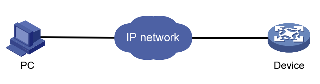
The device is provided with the default Web login information. You can use the following default information to log in to the Web interface:
To log in to the device through the Web interface:
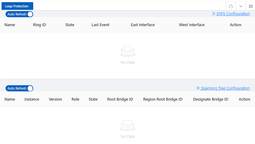
Click Logout button in Auxiliary area to quit Web-based network management, as shown in Figure 1-3. The system does not save the current configuration before you log out of the Web interface. Therefore, we recommend that you save the current configuration before logout.
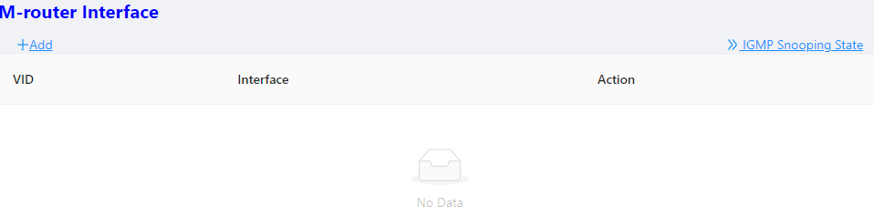
The save configuration module provides the function to save the current configuration to the configuration file for the next startup.
Click the Save button in Auxiliary area to save the current configuration to the configuration file, as shown in Figure 1-4.
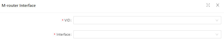
Click Reboot button in Auxiliary area to reboot the device, as shown in Figure 1-5.
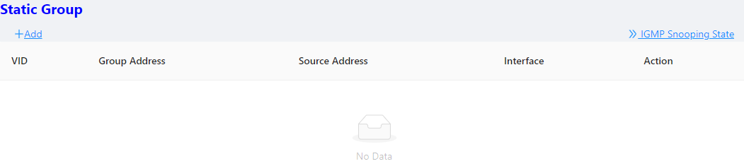
The Web interface is composed of three parts: navigation area, auxiliary area, and body area, as shown in Figure 1-6.
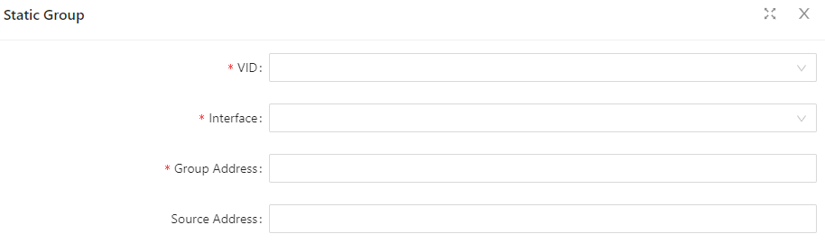
(1)Navigation area (2)Auxiliary area (3)Body area
Select Monitor > Overview from the navigation tree to enter the overview page. As shown in Figure 2-1, The overview page is divided into 3 sections, namely "System Information", "Panel Port", and "Traffic".
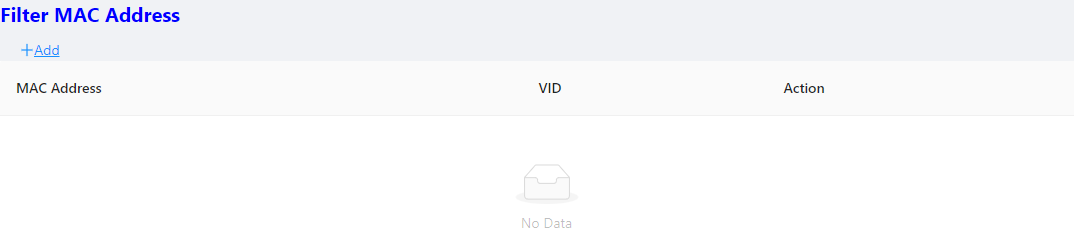
Table 2-1: Basic Information configuration items
| Item | Description |
|---|---|
| Host Name | Displays the device name. Allows user to change it. |
| MAC Address | Displays the device’s MAC address. |
| Hardware Version | Displays the device’s hardware version. |
| Software Version | Displays the device’s software version. |
| Release Date | Displays the device software’s release date. |
| Product SN | Displays the device’s serial number. |
| CPU Used | Displays the device’s cpu status. |
| Memory Avail | Displays the device’s memory status. |
| System Uptime | Displays the time from last system start. |
The port statistics module displays statistics about the packets received and sent through
interfaces.
Displaying port statistics
Select Monitor > Port Statistics in the navigation area to enter the page shown in Figure 2-2. The page displays the port’s Rx Load, Tx Load, Speed, Under size, Over size, CRC Error, Collision Count. Table 2-2 describes the items of port statistics.
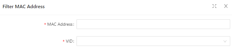
The “Loop Protection” page is used to display the working status of device loop-related protocols, such as ERPS and Spanning Tree protocols.
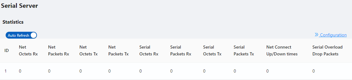
The "Serial Server State" page is used to display the working status of Serial Server.
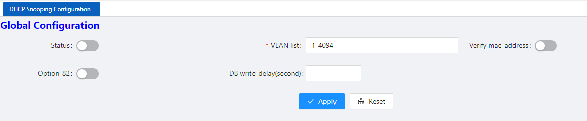
Table 2-3: Items of Serial Server
| Item | Description |
|---|---|
| ID | Serial port ID number of the serial port server |
| Net Octets Rx | The number of bytes received by the network |
| Net Packets Rx | The number of packets received by the network |
| Net Octets Tx | The number of bytes sent by the network |
| Net Packets Tx | The number of packets sent by the network |
| Serial Octets Rx | The number of bytes received by the serial port |
| Serial Packets Rx | The number of packets received by the serial port |
| Serial Octets Tx | The number of bytes sent by the serial port |
| Serial Packets Tx | The number of packets sent by the serial port |
| Net Connect Up/Down times | Number of network connections |
| Serial Overload Drop Packets | Number of packets discarded by serial port overflow |
The "Security" page is used to display the working status of device security-related protocols, with three parts: port security, IP Source Guard, and MAC authentication.

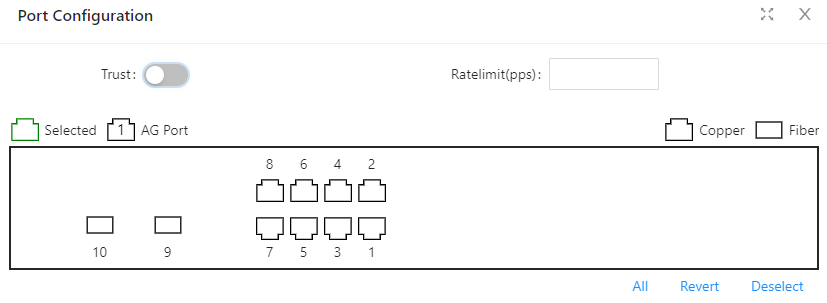
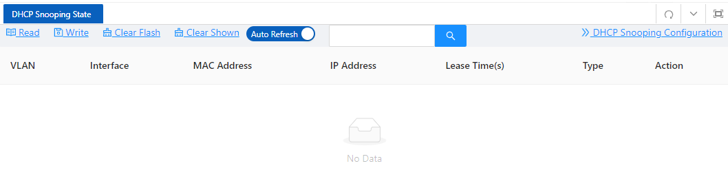
The " PoE State" page is used to display the current PoE working status of the device. (1) Select Monitor > PoE State in the navigation bar to enter the PoE status page, as shown in Figure 2-8.
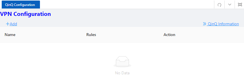
(2) On the current page, you can see the total power supply of the device, the number of power supply ports, and the power supply status of each port. Specific parameter descriptions are shown in Table 2-4.
The LLDP Status page is used to display the device LLDP working status.
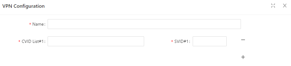
The "IGMP Snooping State" page is used to display the working status of the device IGMP Snooping protocol.
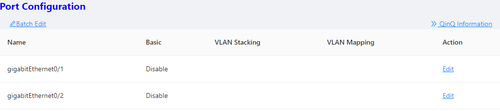
The “DHCP Snooping State” page is used to display the working status of the DHCP Snooping protocol of the device.
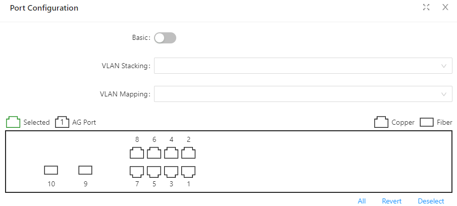
The "QinQ Information" page is used to display the working status of the device QinQ information.
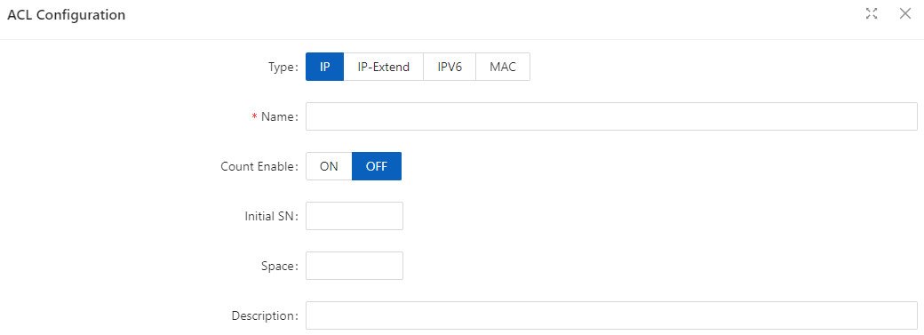
The "LoopDetect State" page is used to display the working status of the loop.
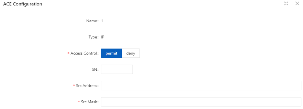
The "ARP Information" page is used to display the working status of the device ARP information.
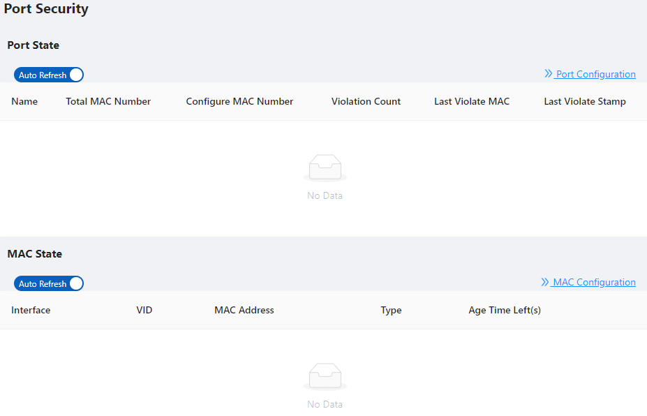
3.1.1 Introduction Ethernet is a network technology based on the Carrier Sense Multiple Access/Collision Detect (CSMA/CD) mechanism. As the medium is shared, collisions and excessive broadcasts are common on an Ethernet. To address the issue, virtual LAN (VLAN) was introduced. The idea is to break a LAN down into separate VLANs, that is, Layer 2 broadcast domains whereby frames are switched between ports assigned to the same VLAN. VLANs are isolated from each other at Layer 2. A VLAN is a bridging domain, and ll broadcast traffic is contained within it, as shown in Figure 3-1.
A VLAN is logically divided on an organizational basis rather than on a physical basis. For example, all workstations and servers used by a particular workgroup can be connected to the same LAN, regardless of their physical locations. VLAN technology delivers the following benefits:
You can create VLANs based on:
Because the Web interface is available only for port-based VLANs, this chapter introduces only port-based VLANs. 3.1.1.1 VLAN Mode Depending on the tag handling mode, the VLAN Mode of a port can be one of the following three:
An access port belongs to only one VLAN and usually connects to a user device.
A trunk port can join multiple VLANs to receive and send traffic for them. It usually connects to a network device.
A hybrid port can join multiple VLANs to receive and send traffic for them. It can connect either a user device or a network device.
A hybrid port is different from a trunk port in that:
3.1.1.2 Port link type
By default, VLAN 1 is the default VLAN for all ports. However, you can change the default VLAN for a port as required. When doing that, follow these guidelines:
3.1.1.3 Frame handling methods
Table 3-1: A port configured with a default VLAN handles a frame as follows:
| Port type | Actions (in the inbound direction) |
|---|---|
| Actions (in the outbound direction) | |
| Untagged frame | Tag the frame with the default VLAN tag. |
| • Receive the frame if its VLAN ID is the same as the default VLAN ID | • Drop the frame if its VLAN ID is different from the default VLAN ID. |
| Remove the default VLAN tag and send the frame. | |
| Trunk | Check whether the default VLAN is carried on the port: |
| • If yes, tag the frame with the default VLAN tag. | • If not, drop the frame. |
| • Receive the frame if its VLAN is carried on the port. | • Drop the frame if its VLAN is not carried on the port. |
| • Remove the tag and send the frame if the frame Carries the default VLAN tag. | • Send the frame without removing the tag if its VLAN is carried on the port but is different from the default one. |
| Hybrid | Send the frame if its VLAN is carried on the port. The frame is sent with the VLAN tag removed or intact depending on your configuration. |
3.1.2 Configuring VLAN 3.1.2.1 Creating VLAN
Table 3-2: Vlan configuration items
| Item | Description |
|---|---|
| ID | This field displays the ID of the VLAN |
| name | By default, the description string of a VLAN is its VLAN ID, such as VLAN 0002. |
| Members | Indicates that the port sends the traffic of the VLAN without removing the VLAN tag. |
| Edit | Click to enter the VLAN editing page |
| Add | Click to enter the VLAN adding page |
| Delete | Select the VLAN ID, click to delete |
3.1.2.2 Configuring Trunk Port
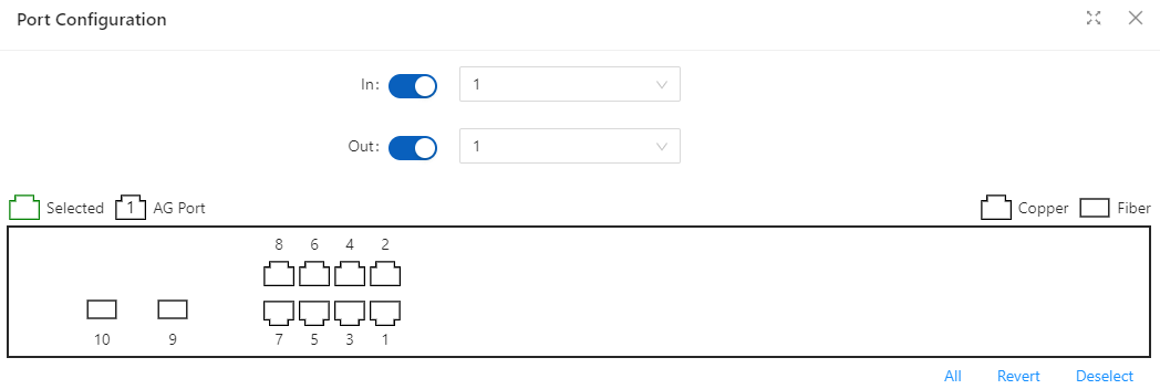
Table 3-3: The description of the Trunk configuration
| Item | Description |
|---|---|
| Mode | Access |
| Set the port’s default VLAN ID, only exist in access mode. | The trunk ports at the two ends of a link must have the same PVID. Otherwise, the link cannot properly transmit packets |
| Native Vlan | VLAN(Native Vlan), only exist in Trunk mode. |
| Allow VLANs | Select the VLANs that are allowed through the port. |
3.2.1 Port Configuration
You can use the interface management feature to view interface information, create/remove logical interfaces, change interface status, and reset interface parameters, as shown in Figure 3-6.
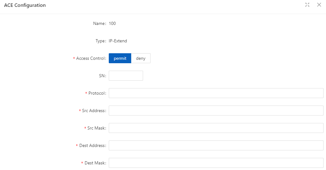
Configuring interface management
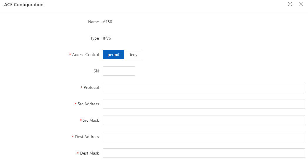
Table 3-4: Configuration items of Port
| Item | Description |
|---|---|
| Admin State | Shutdown/no shutdown the port. |
| Description | Set the description of a logical interface. |
| Port Mode | Set the port’s vlan mode, Access or Trunk |
| PVID/Native VLAN | Set the port’s PVID or Native VLAN. |
| Medium type | Set the medium type of the Combo ports |
| • RJ45:the mode of port is 10/100/1000BASE-T | • SFP:the mode of port is 1000BASE-X |
| Note: only for combo ports. | |
| Speed(copper) | Set the port’s transmission rate: |
| • 10: indicates 10 Mbps | • 100M:indicates 100 Mbps |
| • 1000M:indicates 1000 Mbps | • Auto: indicates auto-negotiation |
| Note: only for copper ports. | |
| Duplex(copper) | Set the port’s duplex mode: |
| • AUTO:indicates auto-negotiation | |
| • FULL:indicates full duplex | |
| • HALF:indicates half duplex | |
| Set the port’s mode | • 100BASE-FX:indicates the port mode is 100BASE-FX. |
| • 1000BASE-X:indicates the port mode is 1000BASE-X. | • 2500BASE-X:indicates the port mode is 2.5G BASE-X. |
| • 10G BASE-X: indicates the port mode is 10G BASE-X. | Note: only for fiber ports. |
| Autoneg(fiber) | Enables or disables port’s autoneg. |
| The auto-negotiation function needs to be enabled or disabled at the same | time as the peer end, otherwise a link failure will occur. |
| Note: only for fiber ports. | |
| Flow control | Enables or disables port’s Flow control. |
| MTU | Allows or forbids jumbo frames to pass through the port. Default length of packets is 46-1500 bytes. |
| Admin Shutdown | Shutdown/no shutdown the port. |
3.2.2 Port Extension 3.2.2.1 Rate Limiting Port-based rate limiting allows you to limit the speed at which network traffic is sent or received by a device that is connected to a port on your switch. Unlike 802.1p Quality of Service (QoS), port-based rate limiting does not prioritize information based on type. Rate limiting simply means that the switch will slow down traffic on a port to keep it from exceeding the limit that you set. If you set the rate limit on a port too low, you might see degraded video stream quality, sluggish response times during online activity, and other problems.
The best use of rate limiting is to keep low-priority devices that are connected to your switch from using too much of your bandwidth and slowing down your other connected devices. A combination of rate limiting and QoS can help you maximize your network’s efficiency and prioritize devices and activities.
Configuring Port Ratelimit
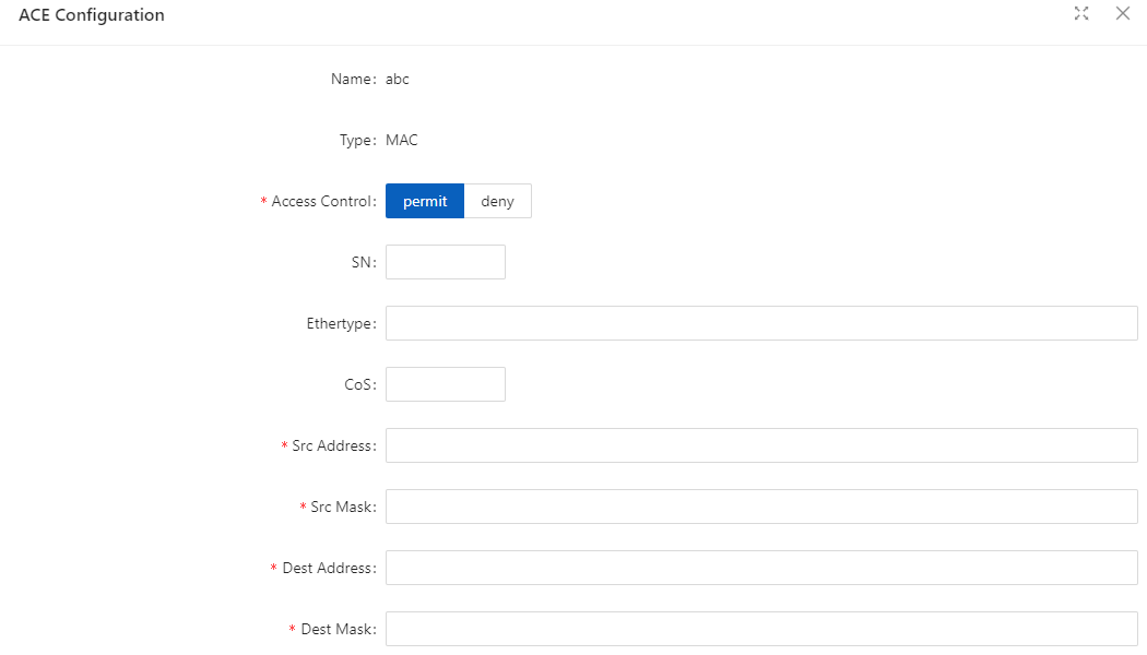

Table 3-5: Port Ratelimit Configuration items
| Item | Description |
|---|---|
| In CIR (kbps) | Specify the rate limit in the inbound direction (KBits). |
| In CBS (KB) | Specify the burst size in the inbound direction (KBits). |
| Out CIR (kbps) | Specify the rate limit in the outbound direction (KBits). |
| Out CBS (KB) | Specify the burst size in the outbound direction (KBits). |
3.2.2.2 Storm Control A traffic storm occurs when a large amount of broadcast, multicast, or unicast packets congest a network.
You can use the storm suppression function to limit the size of a particular type of traffic (currently broadcast, multicast and unknown unicast traffic) on a per-interface basis in Ethernet port view or port group view.
In interface or port group view, you set the maximum broadcast, multicast or unknown unicast traffic allowed to pass through an interface or each interface in a port group. When the broadcast, multicast, or unknown unicast traffic on the interface exceeds the threshold, the system discards packets until the traffic drops below the threshold.
Configuring the Storm Control

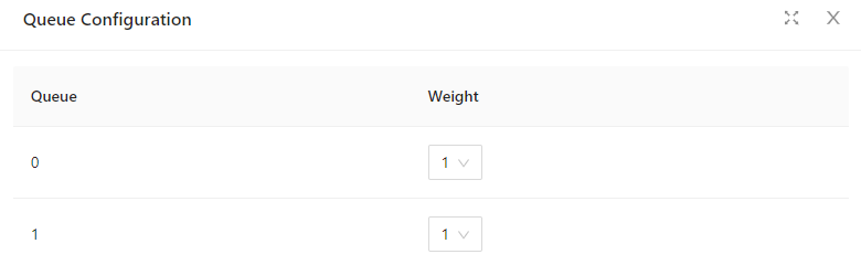
Table 3-7: Items of the storm control
| Item | Description |
|---|---|
| Type | Disabled |
| Selects the parameter used in broadcast suppression and sets its | value in the percentage box. |
| Multicast | Selects the parameter used in multicast suppression and sets its |
| value in the percentage box. | |
| Unicast | Selects the parameter used in unicast suppression and sets its |
| value in the percentage box. | |
| multicast-broadcast | Selects the parameter used in multicast and broadcast |
| suppression and sets its value in the percentage box. | |
| unicast-broadcast | Selects the parameter used in unicast and broadcast, |
| suppression and sets its value in the percentage box. | |
| All | Selects the parameter used in unicast and unicast, |
| broadcast, suppression and sets its value in the percentage box. | |
| Percentage (%) | Indicates the maximum percentage of traffic to the total |
| transmission capability of an Ethernet interface. |
3.2.2.1 Isolation Usually, Layer 2 traffic isolation is achieved by assigning ports to different VLANs. To save VLAN resources, port isolation is introduced to isolate ports within a VLAN, allowing for great flexibility and security.
Configuring an Isolation Group
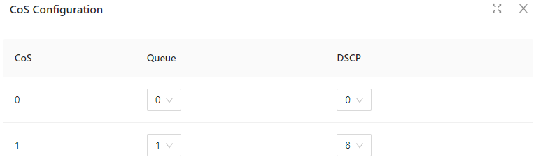
3.2.3 Port Mirroring Port mirroring is to copy the packets passing through one or multiple ports (called source interface) to a port (called the destination interface) on the local device. The source interface is connected with a monitoring device. By analyzing on the monitoring device, the packets mirrored to the destination interface, you can monitor the network and troubleshoot possible network problems.
Figure3-13 A port mirroring implementation Creating a mirroring group
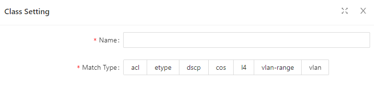
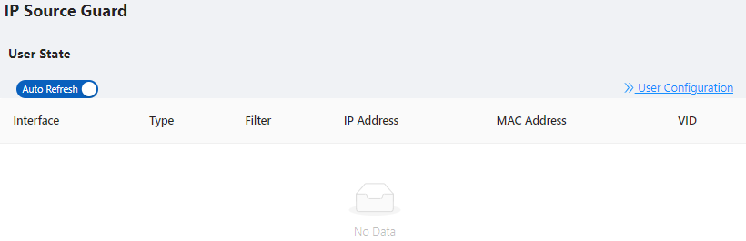
Table 3-8: Configuration items of creating a mirroring group
| Item | Description |
|---|---|
| Session | ID of the mirroring group to be created |
| Destination Interface | the monitor port for the mirroring group, there can only be one |
| Source Interface | mirroring ports for the mirroring group, there can be more than one |
3.2.4 Port Aggregation 3.2.4.1 Overview Link Aggregation Ethernet link aggregation, most often simply called link aggregation, aggregates multiple physical Ethernet links into one logical link to increase link bandwidth beyond the limits of any one single link. This logical link is called an aggregate link. It allows for link redundancy because the member physical links dynamically back up one another.
As shown in Figure 3-16, Switch A and Switch B are connected with three physical Ethernet links. These physical Ethernet links are aggregated into an aggregate link, Link aggregation 1. The bandwidth of this aggregate link can be as high as the total bandwidth of these three physical Ethernet links.
LACP
The IEEE 802.3ad Link Aggregation Control Protocol (LACP) enables dynamic aggregation of physical links. It uses link aggregation control protocol data units (LACPDUs) for exchanging aggregation information between LACP-enabled devices.
There are two link aggregation modes: dynamic and static. Dynamic link aggregation uses LACP while static link aggregation does not. A link aggregation group operating in static mode is called a static link aggregation group, while a link aggregation group operating in dynamic mode is called a dynamic link aggregation group. 3.2.4.2 Configuring an Aggregation Group
Configuration procedure:
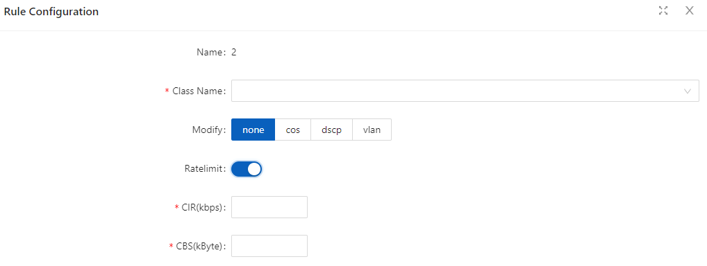
Table 3-9: description of global configure item
| Item | Description |
|---|---|
| Equalize according to the destination MAC address and source MAC address | |
| dst-ip | Equalize according to the destination IP address |
| srt-ip | Equalize according to the source IP address |
| src-dst-ip | Equalize according to the destination IP address and source IP address |
| dst-port | Equalize according to the L4 TCP/UDP destination port number |
| src-port | Equalize according to the L4 TCP/UDP source port number |
| src-dst-port | Equalize according to the L4 TCP/UDP destination port number and source port number |
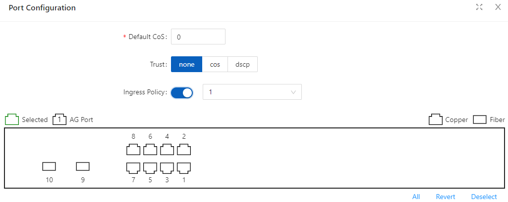

Table 3-10: description of Aggregation Member
Table 3-11: description of Aggregation port
| Item | Description |
|---|---|
| Aggregation | |
| The member ports of the Aggregation Port |
3.2.5 Port Violation During the use of the device, active or passive violations may occur on the switch port, such as port security violations, port flapping violations, port loop detection violations, etc. The port violation module is used to configure the recovery enablement and recovery time of the violating port, and displays the port's violation behavior.
Configuration procedure:
Select Configuration > Port > Port Violation in the navigation bar to enter the port violation global configuration interface, check the service that needs to be violated, turn on the automatic recovery button and configure the recovery time, click the Apply button to complete the configuration, such as Figure 3-40 is shown, and the global configuration parameters are shown in Table 3-13.
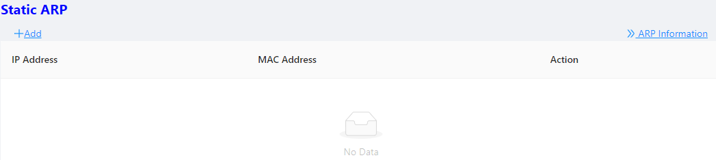
3.3.1 Overview Spanning Tree Protocol (STP) is a Layer-2 management protocol. It cannot only selectively block redundant links to eliminate Layer-2 loops but also can back up links.
Like many protocols, STP is continuously updated from Rapid Spanning Tree Protocol (RSTP) to Multiple Spanning Tree Protocol (MSTP) as the network develops.
For the Layer-2 Ethernet, only one active link can exist between two local area networks (LANs). Otherwise, a broadcast storm will occur. To enhance the reliability of a LAN, it is necessary to establish a redundant link and keep some paths in backup state. If the network is faulty and a link fails, you must switch the redundant link to the active state. STP can automatically activate the redundant link without any manual operations. STP enables devices on a LAN to:
Discover and start the best tree topology on the LAN.
Troubleshoot a fault and automatically update the network topology so that the possible best tree topology is always selected.
The LAN topology is automatically calculated based on a set of bridge parameters configured by the administrator. The best topology tree can be obtained by properly configuring these parameters.
RSTP is completely compatible with 802.1D STP. Like traditional STP, RSTP provides loop-free and redundancy services. It is characterized by rapid speed. If all bridges in a LAN support RSTP and are properly configured by the administrator, it takes less than 1 second (about 50 seconds if traditional STP is used) to re-generate a topology tree after the network topology changes.
STP and RSTP have the following defects:
STP migration is slow. Even on point-to-point links or edge ports, it still takes two times of the forward delay for ports to switch to the forwarding state.
RSTP can rapidly converge but has the same defect with STP: Since all VLANs in a LAN share the same spanning tree, packets of all VLANs are forwarded along this spanning tree. Therefore, redundant links cannot be blocked according to specific VLANs and data traffic cannot be balanced among VLANs.
MSTP, defined by the IEEE in 802.1s, resolves defects of STP and RSTP. It cannot only rapidly converge but also can enable traffic of different VLANs to be forwarded along respective paths, thereby providing a better load balancing mechanism for redundant links.
In general, STP/RSTP works based on ports while MSTP works based on instances. An instance is a set of multiple VLANs. Binding multiple VLANs to one instance can reduce the communication overhead and resource utilization. 3.3.2 Spanning Tree Configuring Global Configuration of the Spanning Tree
Select Configuration > Spanning Tree > Global Configuration in the navigation area to enter the Global Configuration page, as shown in Figure 3-20. Table 3-12 describes the Spanning Tree Global Configuration items.
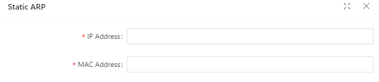
Table 3-12: Spanning Tree Global Configuration items
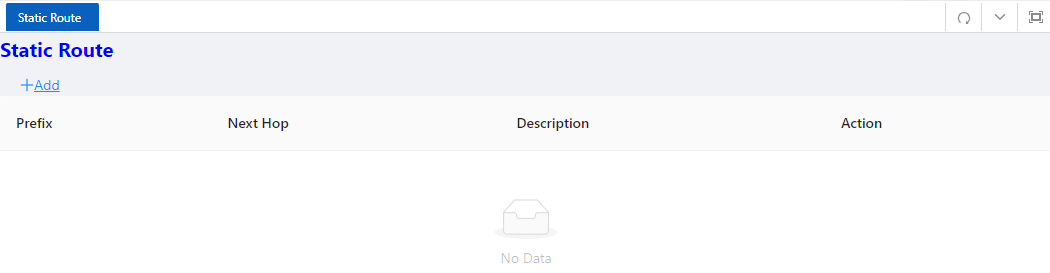
Table 3-13: Spanning Tree Instance items
3.4.1 Overview
The ITU-T G.8032 ERPS feature implements protection switching mechanisms for Ethernet layer ring topologies. This feature uses the G.8032 Ethernet Ring Protection (ERP) protocol, defined in ITU-T G.8032, to provide protection for Ethernet traffic in a ring topology, while ensuring that no loops are within the ring at the Ethernet layer. The loops are prevented by blocking traffic on either a predetermined link or a failed link.
Initial State
As the following figure, the devices on the ring have been configured, and all the link status is up.
The RPL owner interface will be blocked by ERPS protocol to prevent loops. If a RPL neighbor interface is configured, it will also be blocked. Other interfaces are under the forwarding state, can forward the traffic.
Link failure
When there is a link failure between SwitchD and SwitchE, the two interfaces on the link will be blocked by ERPS protocol, the RPL owner interface will be forwarded.
Figure 1 Link failure Link restores
When the failure link is restored. When the erps ring is configured to revertive mode, the RPL owner interface will be blocked by ERPS protocol, the restored link will be configured to forwarding state to forward traffic.
Single-Ring: Only one ring in a network topology needs to be protected.
In Figure 3-23, the network topology has only one ring, only one ring protection link (RPL) owner node, and only one RPL. All nodes must belong to the same ring automatic protection switching (R-APS) virtual local area network (VLAN).
All devices in the ring network must support ERPS.
The links between devices in the ring network must be directly connected, and there must be no intermediate devices.
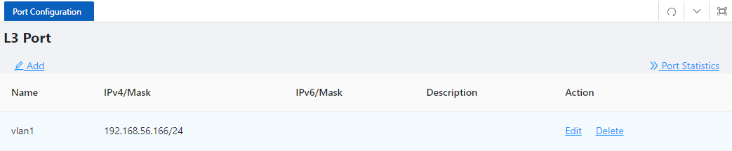
Tangent Rings:
The two rings in a network topology that share one device need to be protected.
In Figure 3-24, the two rings in the network topology share one device. Each ring has only one PRL owner node and only one RPL. The two rings belong to different R-APS VLANs.
All devices in the ring network need to support ERPS.
The links between devices in the ring network must be directly connected, and there must be no intermediate devices.
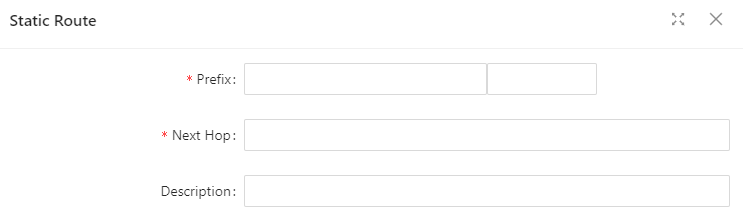
Intersecting Rings: Two or more rings in a network topology share one link. (Each link between intersecting nodes must be a direct link without any intermediate node.)
In Figure 3-25, four rings exist in the network topology. Each ring has only one PRL owner node and only one RPL. The four rings belong to different R-APS VLANs.
All devices in the ring network need to support ERPS.
The links between devices in the ring network must be directly connected, and there must be no intermediate devices.

3.4.2 Configure the ERPS Ring Configuration
Select Configuration > ERPS > Ring Configuration in the navigation area to enter the ERPS Ring Configuration page as shown in Figure 3-26, The description of the ERPS Ring Configuration is described in Table 3-15.


Table 3-15: Ring Configuration description
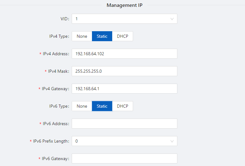

Table 3-16: Description of the ERPS Instance Configuration
3.5.1 PoE Overview Power over Ethernet (PoE) means that power sourcing equipment (PSE) supplies power to powered devices (PDs) from Ethernet interfaces through twisted pair cables. 3.5.2 PoE Configuration
3-30, the Table 3-18 describes the items of PoE Global Configuration.
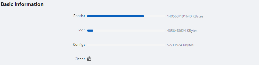
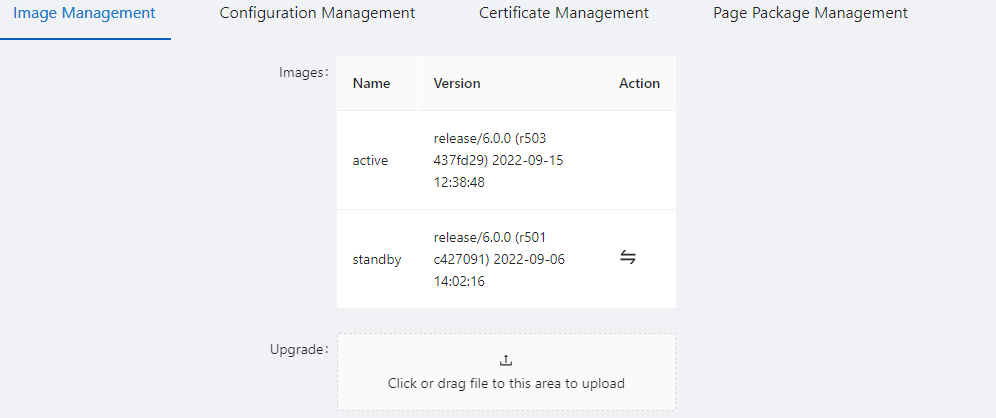
Table 3-18: description of PoE Global Configuration
| Item | Description |
|---|---|
| Power supply (w) | By default, the default power provided by the device is 15.4W*port number, for example, the maximum power provided by an 8-port device is 123.2W |
| • For devices with external power supply, please fill in this parameter according to the actual configured power supply | • For devices with built-in power supply, please refer to the description of PoE power in the product manual for this parameter |
| Power reserved (%) | Reserved power set against power fluctuations |
| • For devices with external power supply, it is recommended to fill in the power consumption of the main board | • For devices with built-in power supply, this parameter can be set 0 by default |
| Power | management |
| Display the mode of power management is energy-saving. In this mode, the power requested and allocated to the port is based on the actual port's (real time) power consumption. | |
| Disconnect mode | Display the mode of disconnection is DC disconnect |
| Alarm state | Turn on/off the log alarm when the power is insufficient |
| Power alarm (%) | Alarm power limit setting, when the PoE power consumption exceeds this value, the system will automatically output a log alarm |
| • Click Batch Edit below “port configuration” to enter PoE port configuration page, Select the port to be configured, as shown in Figure 3-31. |
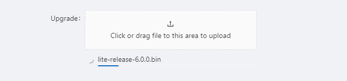
3.6.1 Port Security 3.6.1.1 Overview
The Port Security function restricts the number of valid MAC addresses on the port to limit the access of illegal users to the port. The illegal MAC packets will be directly discarded.
The legal MAC can be generated statically or dynamically. The static legal MAC is generated through user command line configuration; the dynamic legal MAC is dynamically generated through the MAC address learning function.
When the number of secure addresses on the port has reached the configured value of the maximum number of secure addresses, the new MAC access port will be recognized as an illegal MAC and a violation event will be generated. The user can configure the actions to be taken when the violation event occurs, respectively restrict or shutdown the port.
Restrict: Prohibit illegal MAC data from passing, and generate alarm log prompt information. Illegal MAC will prohibit access to the port within the MAC address aging time. It can be restored through shutdown and no shutdown ports.
Shutdown: The port is forced to be down, and the port recovery time can be configured. The port will automatically recover when the time is up; it can also be recovered by the shutdown, no shutdown command.
If you want to convert a dynamic security user to a static security user, you can enable the sticky function on the port. When the sticky function is enabled on the port, the dynamic users learned on the port will exist as static users. If the configuration is saved, the device will still exist after restarting the device.
3.6.1.2 Configuring Port Security Port Configuration
Select Configuration > Security > Port security in the navigation area to enter the Port security page as shown in Figure 3-33.
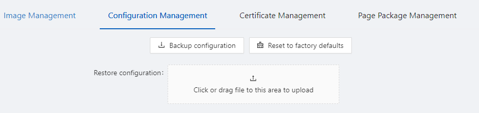
Click the Batch Edit button below “Port Configuration” to enter the Port Configuration page, as shown in Figure 3-34. The items of the port configuration are described in Table 3-20.



Table 3-20: the items of the port security configuration
Table 3-21: the items of the mac configuration
| Item | Description |
|---|---|
| MAC | Configuration |
| Interface | Select the interface to be configured. |
| MAC Address | Configure a static security address, the format of the security address: XXXX.XXXX.XXXX |
| The security address cannot be a broadcast or multicast Address. | |
| Type | Configure the MAC address as dynamic or static. |
3.6.2 IP Source Guard 3.6.2.1 Overview IP Source Guard:
The Ip Source Guard binding function allows IP packets conforming to the IP+MAC binding to pass through the port, and non-conforming packets are directly discarded, thereby achieving the purpose of preventing IP/MAC spoofing attacks.
The binding entries of Ip Source Guard mainly come from two sources: user static configuration and dynamic acquisition in the ip dhcp snooping environment.
User static configuration: mainly for host users whose IP addresses are statically configured in the local area network.
Ip dhcp snooping dynamic acquisition: mainly respond to the host users who dynamically acquire the IP address through dhcp in the local area network.
IP/MAC spoofing attack: Illegal MAC users send IP packets with legal source IP to realize the legalization of access identity.
ARP Check:
The Arp-check (ARP packet check) function filters all ARP packets under the port and discards all illegal ARP packets, which can effectively prevent ARP spoofing in the network and improve the stability of the network.
In the device that supports the Arp-check function, the Arp-check function can generate corresponding ARP filtering information based on the legal user information (IP+MAC) generated by the security application modules such as IP Source Guard, so as to realize the illegal ARP packets filtering in the network. 3.6.2.2 Configuring IP Source Guard
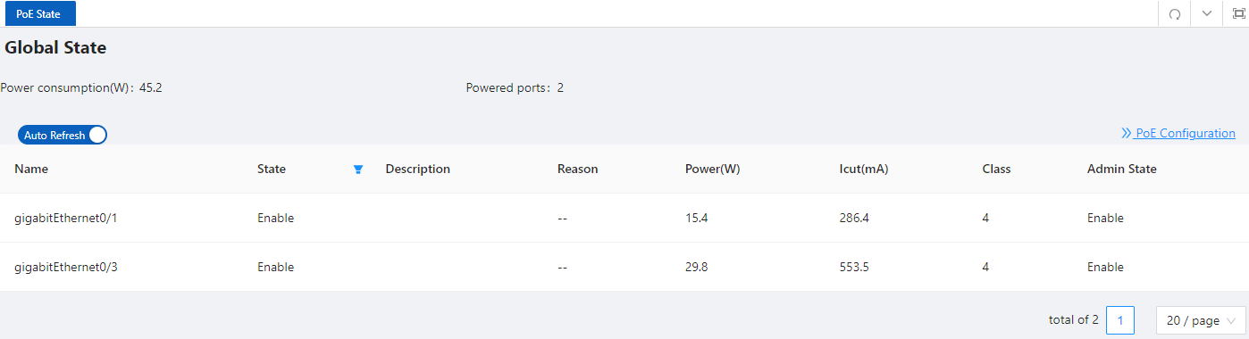
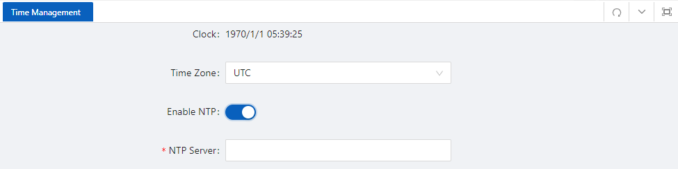
Click OK button, the rules created were displayed in summary page as shown in Figure 3-39.

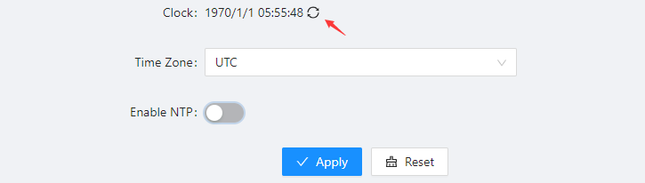
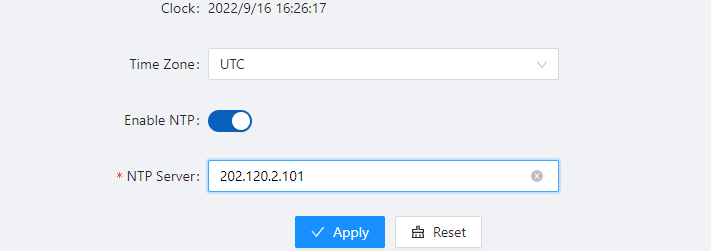
3.6.2.3 Configuring ARP Check
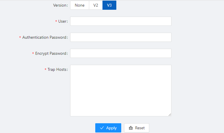

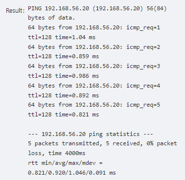
3.6.3 Dot1X 3.6.3.1 Overview
The 802.1X(Dot1X) protocol was proposed by the IEEE 802 LAN/WAN committee for security of wireless LANs (WLAN). It has been widely used on Ethernet as a common port access control mechanism.
As a port-based access control protocol, 802.1X authenticates and controls accessing devices at the port level. A device connected to an 802.1X-enabled port of an access control device can access the resources on the LAN only after passing authentication.
Architecture of 802.1X 802.1X operates in the typical client/server model and defines three entities: Client, Device, and Server, as shown in below.
Client is an entity seeking access to the LAN. It resides at one end of a LAN segment and is authenticated by Device at the other end of the LAN segment. Client is usually a user-end device such as a PC. 802.1X authentication is triggered when an 802.1X-capable client program is launched on Client. The client program must support Extensible Authentication Protocol over LAN (EAPOL).
Device, residing at the other end of the LAN segment, authenticates connected clients. Device is usually an 802.1X-enabled network device and provides access ports (physical or logical) for clients to access the LAN.
Server is the entity that provides authentication services to Device. Server, normally running RADIUS (Remote Authentication Dial-in User Service), serves to perform authentication, authorization, and accounting services for users.
Authentication modes of 802.1x
The 802.1X authentication system employs the Extensible Authentication Protocol (EAP) to exchange authentication information between the client, device, and authentication server. Client Device Server Between the client and the device, EAP protocol packets are encapsulated using EAPOL to be transferred on the LAN.
Between the device and the RADIUS server, EAP protocol packets can be exchanged in two modes: EAP relay and EAP termination. In EAP relay mode, EAP packets are encapsulated in EAP over RADIUS (EAPOR) packets on the device, and then relayed by device to the RADIUS server. In EAP termination mode, EAP packets are terminated at the device, converted to RADIUS packets either with the Password Authentication Protocol (PAP) or Challenge Handshake Authentication Protocol (CHAP) attribute, and then transferred to the RADIUS server.
Basic concepts of 802.1x These basic concepts are involved in 802.1X: controlled port/uncontrolled port, authorized state/unauthorized state, and control direction.
Controlled port and uncontrolled port A device provides ports for clients to access the LAN. Each port can be regarded as a unity of two logical ports: a controlled port and an uncontrolled port. Any packets arriving at the port are visible to both logical ports.
The uncontrolled port is always open in both the inbound and outbound directions to allow EAPOL protocol packets to pass, guaranteeing that the client can always send and receive authentication packets.
The controlled port is open to allow data traffic to pass only when it is in the authorized state.
Authorized state and unauthorized state
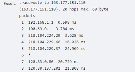
A controlled port can be in either authorized state or unauthorized state, which depends on the authentication result, as shown in Figure 3-45.
You can control the port authorization status of a port by setting port authorization mode to one of the following:
Force-Authorized: Places the port in authorized state, allowing users of the port to access the network without authentication.
Force-Unauthorized: Places the port in unauthorized state, denying any access requests from users of the port.
Auto: Places the port in the unauthorized state initially to allow only EAPOL packets to pass, and turns the port into the authorized state to allow access to the network after the users pass authentication. This is the most common choice.
Control direction
In the unauthorized state, the controlled port can be set to deny traffic to and from the client or just the traffic from the client. 802.1X authentication triggering 802.1X authentication can be initiated by either a client or the device.
Unsolicited triggering of a client A client can initiate authentication unsolicitedly by sending an EAPOL-Start packet to the device. The destination address of the packet is 01-80-C2-00-00-03, the multicast address specified by the IEEE 802.1X protocol.
Some devices in the network may not support multicast packets with the above destination address, and unable to receive authentication requests of clients as a result. To solve this problem, the device also supports EAPOL-Start packets using a broadcast MAC address as the destination address.
Unsolicited triggering of the device
The device can trigger authentication by sending EAP-Request/Identity packets to unauthenticated clients periodically (every 30 seconds by default). This method can be used to authenticate clients that cannot send EAPOL-Start packets unsolicitedly to trigger authentication, for example, a client running the 802.1X client application provided by Windows XP.
Authentication process of 802.1x An 802.1X device communicates with a remote RADIUS server in two modes: EAP relay and EAP termination. The following describes the 802.1X authentication procedure in the two modes, which is triggered by the client in the examples.
EAP relay EAP relay is defined in IEEE 802.1X. In this mode, EAP packets are carried in an upper layer protocol, such as RADIUS, so that they can go through complex networks and reach the authentication server. Generally, relaying EAP requires that the RADIUS server support the EAP attributes of EAP-Message and Message-Authenticator, which are used to encapsulate EAP packets and protect RADIUS packets carrying the EAPMessage attribute respectively.
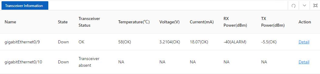
3.6.3.2 Configuring Dot1X
Select Security > Dot1x> Configuration from the navigation area. The system automatically displays the 802.1X Global Configuration and Port Configuration, as shown in Figure 3-47 and Figure 3-48. Table 3-22 and Table 3-23 describes the Global Configuration and Port Configuration items.
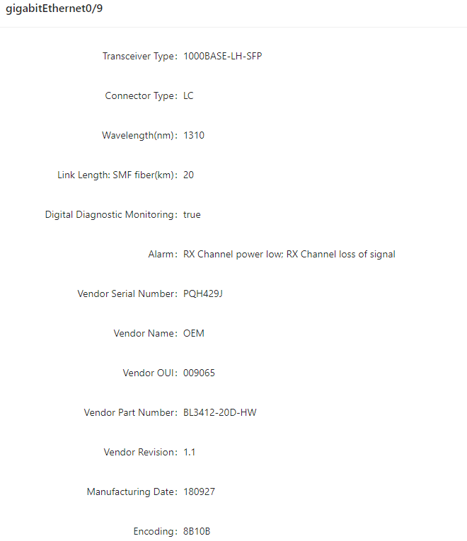
Table 3-22: The 802.1X Configuration items
Table 3-23: The 802.1X port Configuration items
| Item | Description |
|---|---|
| Port | Configuration |
| Name | Physical interface name |
| Port Control | Port control mode |
| Protocol Version | Eapol protocol version, default version 2 |
| Quiet Period(s) | Sets the number of seconds that the switch remains in the quiet-period following a failed authentication exchange with the client. The range is 0 to 65,535 seconds; the default is 60. |
| When the switch cannot authenticate the client, the switch remains idle for a set period, and then tries again. The idle time is determined by the quiet-period value. | |
| Tx Period(s) | Sets the number of seconds that the switch waits for a response to an EAP-request/identity frame from the client before retransmitting the request. The range is 1 to 65,535 seconds; the default is 30. |
| ReAuth Enabled | Enables periodic reauthentication of the client |
| ReAuth Period(s) | Specifies the number of seconds between reauthentication attempts or have the switch use a RADIUS-provided session timeout. The range is 1 to 65,535; the default is 3600 seconds. This command affects the behavior of the switch only if periodic reauthentication is enabled. |
| Supp Timeout(s) | Sets the number of seconds that the switch waits for a response to an EAP-Request/MD5 Challenge frame from the client before retransmitting the request. The range is 1 to 65,535 seconds; the default is 30. |
| Server Timeout(s) | Sets the number of seconds that the switch waits for a response to a RADIUS Access-Request packet from the server. The range is 1 to 65,535 seconds; the default is 30. |
3.6.4 MAC Auth 3.6.4.1 Overview Authentication of MAC addresses is supported using a RADIUS server that contains a database of all valid users.
When the mac-auth option is enabled on any interface, all source MAC addresses from any incoming frame are sent for authentication. If the username and password of the source address are configured in the RADIUS server, then authentication succeeds, otherwise it fails. When authentication succeeds, the source MAC is added to the forwarding table with forwarding enabled. In the case of failure, the source MAC either is added to the forwarding table as discarded or is added to a restricted VLAN.
3.6.4.2 Configuring MAC authentication Displaying MAC Authentication Summary
Select Configuration > Security > MAC Authentication from the navigation area. The system automatically displays the MAC Authentication summary, as shown in Figure 3-49. Table 3-24 describes the MAC Authentication Summary items.
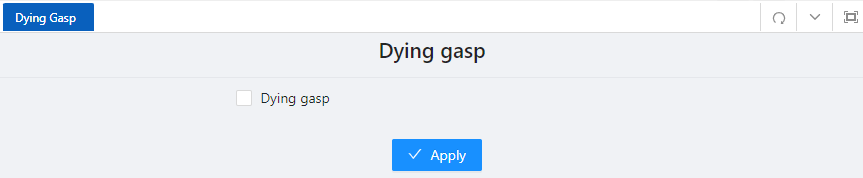
Table 3-24: The MAC Authentication Summary items
| Item | Description |
|---|---|
| Global | Configuration |
| State | Enables the 802.1X feature on your switch. |
| RADIUS | Configuration |
| Click to jump to the RADIUS configuration interface | |
| Port | Configuration |
| Name | Physical interface name |
| State | Display the state of MAC Auth |
| MAC Address Aging | Display the state of MAC Address Aging |
| Action | Click to Edit the rule |
| Select Configuration > Security > MAC Authentication from the navigation area. Click Statebutton in “Global Configuration”, click Apply button to enable the MAC Auth function. | |
| • Configuring Port | Click Batch Edit button below “Port Configuration” to enter the port configuration page, as shown in Figure |
| 3-50. Click State button, select the port to be configured in port panel, click Ok button. |
3.6.5 RADIUS 3.6.5.1 Overview Remote Authentication Dial-In User Service (RADIUS) is protocol for implementing Authentication, Authorization, and Accounting (AAA).
RADIUS is a distributed information interaction protocol using the client/server model. RADIUS can protect networks against unauthorized access and is often used in network environments where both high security and remote user access are required. RADIUS uses UDP, and its packet format and message transfer mechanism are based on UDP. It uses UDP port 1812 for authentication and 1813 for accounting.
RADIUS was originally designed for dial-in user access. With the diversification of access methods, RADIUS has been extended to support more access methods, for example, Ethernet access and ADSL access. It uses authentication and authorization in providing access services and uses accounting to collect and record usage information of network resources.
Client/server model Client: The RADIUS client runs on the NASs located throughout the network. It passes user information to designated RADIUS servers and acts on the responses (for example, rejects or accepts user access requests).
Server: The RADIUS server runs on the computer or workstation at the network center and maintains information related to user authentication and network service access. It listens to connection requests, authenticates users, and returns the processing results (for example, rejecting or accepting the user access request) to the clients.
In general, the RADIUS server maintains three databases: Users, Clients, and Dictionary, as shown in Figure 4-39.
Users: Stores user information such as the usernames, passwords, applied protocols, and IP addresses.
Clients: Stores information about RADIUS clients, such as the shared keys and IP addresses.
Dictionary: Stores information about the meanings of RADIUS protocol attributes and their values.
Security and authentication mechanisms Information exchanged between a RADIUS client and the RADIUS server is authenticated with a shared key, which is never transmitted over the network. This enhances the information exchange security. In addition, to prevent user passwords from being intercepted on insecure networks, RADIUS encrypts passwords before transmitting them.
A RADIUS server supports multiple user authentication methods, for example, the Password Authentication Protocol (PAP) and Challenge Handshake Authentication Protocol (CHAP) of the Point-to-Point Protocol (PPP). Moreover, a RADIUS server can act as the client of another AAA server to provide authentication proxy services.
Basic message exchange process of RADIUS
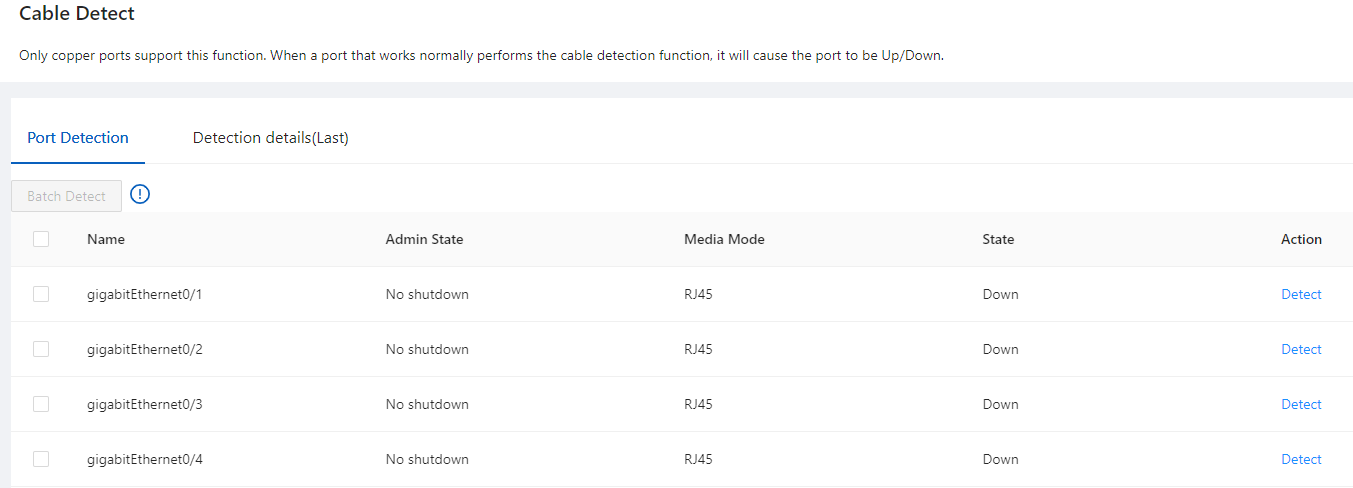
The following is how RADIUS operates:
3.6.5.2 Configuring RADIUS RADIUS global configuration
Select Configuration > Security > RADIUS from the navigation area. The system automatically displays the RADIUS Global Configuration, as shown in Figure 3-52. Table 4-19 describes the RADIUS Global Configuration items.
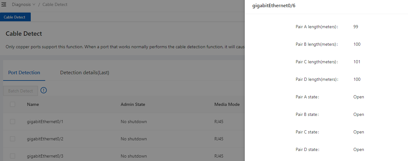
Table 4-19: The RADIUS Global Configuration items
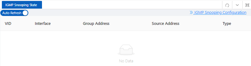
3.7.1 Serial Servers 3.7.1.1 Overview
The serial device server is used to connect serial devices to the Ethernet. The serial device server supports bidirectional conversion and transmission of network data and serial data. Serial device server work in tcp-client mode, as shown in Figure 3-53.
Serial device server in tcp-client mode provides client connections for TCP network servers. it actively initiates a connection and connect to the server to realize the interaction between serial device and tcp server. The Tcp/Ip and serial data are transparently transmitted in both directions. The serial device server supports to establish multiple TCP Clients to connect to different Tcp Server. Serial device server work in tcp-server mode, as show in Figure 3-54.
In TCP Server mode, the module monitors the local port, accepts and establishes a connection for data communication when a connection request is sent. Used for communication with TCP clients within a local area network. It is suitable for scenarios where there is no server in the LAN and there are multiple computers or mobile phones requesting data from the module.
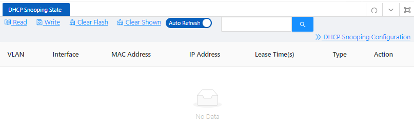
3.7.1.2 Configuring Serial Server
Select Configuration > Control > Serial Server from the navigation area. The system automatically displays the Serial Server Configuration page, as shown in Figure 3-55.
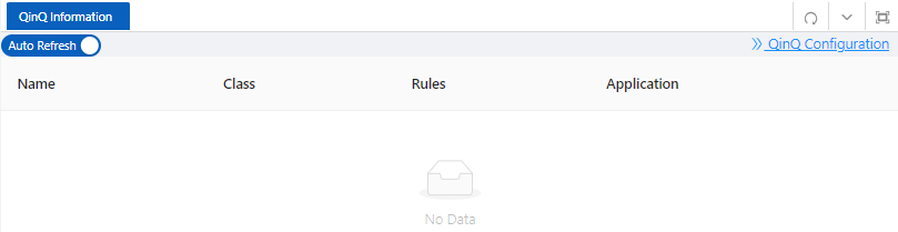
Click Edit button to enter Serial Server Configuration page, as shown in Figure 3-56. Table 3-25 describes the Serial Server Configuration items.
Table 3-25: Serial Server Configuration items
| Item | Description |
|---|---|
| Serial port number | |
| Baud Rate | The baud rate of the serial port is configured, and there are five kinds of options: 9600, 19200, 38400, 57600, and 115200 |
| Data Bits | The data bits of the serial port are configured, and there are two kinds of options: 7 and 8 |
| Parity | There are five types of configuration checksum methods: none, even, odd, mark, and space |
| Stop Bits | There are two options for configuring the stop bit, 1 and 2 |
| Serial port data bits are transmitted at low speed, and the data is transferred from the network end to the serial port side to increase the fifo, improve the forwarding ability, the range < 0-128>, the default 64 | The length of the serial port data packet, beyond the LEGGTH value, the packet is forwarded to the network end, the range <0-1460>, the default is 1460 |
| Interval | If the interval between the bytes before and after the serial port data exceeds MILLISECONDS, the post-byte data is recognized as the new message header byte |
| Configure the serial port server to keep alive, during which there is no data interaction, then active detection is initiated | |
| Client | Remote IP |
| Configure the port number for the remote connection, ranging from < 1-65535> | |
| Local port | For optional configurations, the default system is automatically assigned |
| Configure the tcp-server port number, which < range from 1-65535> | |
| Max connections | The maximum number of connections in tcp-server mode, ranging from 1 to 65535 > |
3.7.2 IO Control IO control module is divided into DI, DO two parts. In current software, DO only supports simple manual control relay (DO) ON/OFF switching function, as shown in Figure 3-57. DI only supports input level high and low judgment, as shown in Figure 3-58.
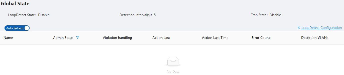

3.8.1 Overview LOOP-DETECT is an Ethernet loop detection protocol, which is used to quickly detect loop faults on downlink interfaces. If a fault is found, LOOP-DETECT will notify the user to manually close or automatically close the relevant port according to the fault handling method configured by the user, so as to avoid affecting the normal data exchange.
Enable control: Enable control is divided into global enable control and port enable control. When the global enable control is enabled and the loop detection is enabled on the port, the port supports the loop detection function.
Loop action: When a loop fault is detected on the port, the user will be notified to manually handle the loop fault by default, and the automatic closing of the port can also be configured. When the port is automatically shut down, the port can recover from the fault by waiting for timeout, shutdown/no shutdown port, recovery command, or restarting the device.
Specify vlan: By default, the port vlan attribute is ignored; if you need to detect whether a loop fault occurs in a specific vlan domain, you can configure the specified vlan on the port, and only detect Whether there is a loop data path in this vlan domain.
The device supports loop fault alarm and loop fault recovery message traps to the snmp server, which is disabled by default. 3.8.2 Configuring LoopDetect LoopDetect Configuration
interval, turn on the Trap switch (optional), and click the Apply button to complete theconfiguration, as shown in Figure 3-59, the Table 3-26 describes the items of PoE Global Configuration.
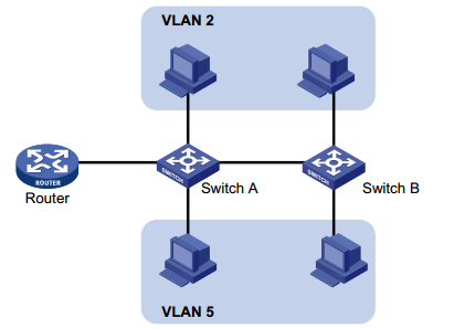
Table 3-26: Loop detection global configuration items
| Items | Description |
|---|---|
| Loop detection | Turn on/off the loop detection function. The default is to turn off globally and the port. |
| Detection interval | Configure loop detection interval, range 5-300 seconds, default 5 seconds |
| Trap | Enable/disable loop fault trap alarm |
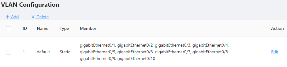
4.1.1 Overview
In a heterogeneous network, a standard configuration exchange platform ensures that different types of network devices from different vendors can discover one another and exchange configuration.
The Link Layer Discovery Protocol (LLDP) is specified in IEEE 802.1AB. The protocol operates on the data link layer to exchange device information between directly connected devices. With LLDP, a device sends local device information as TLV (type, length, and value) triplets in LLDP Data Units (LLDPDUs) to the directly connected devices. Local device information includes its system capabilities, management IP address, device ID, port ID, and so on. The device stores the device information in LLDPDUs from the LLDP neighbors in a standard MIB. LLDP enables a network management system to quickly detect and identify Layer 2 network topology changes.
4.1.2 Configuring LLDP LLDP global Configuration
Select Advance > Layer2 > LLDP Configuration in the navigation area to enter the Global Configuration page, as shown in Figure 4-1. Table 4-1 describes the Global Configuration items.
Table 4-1: LLDP Global Configuration Items
| Item | Description |
|---|---|
| Status | Disabled: global disable |
| Click to enable | LLDP port setting |
port-vlanid: port's vlanid ptcl -identity: protocol id vid-digest: vid digest vlan-name: vlan name port-ptcl – vlanid: port protocol vlanid link- agg mgmt -vid: Link Aggregation Management vid
mac-phy: The rate and duplex status supported by the port, whether it supports port rate auto-negotiation, whether the auto-negotiation function is enabled, and the current rate and duplex status max – mtu -size: maximum mtu value Tx hold Transmission hold, the default value txFastInit is 4, used for packet TTL calculation; TTL= msgTxInterval * msgTxHold + 1 Tx interval Transfer intervals, default is 30 s; admin can change this value to any value between5and 300.
Reinit delay Indicates the amount of delay between when adminStatus becomes ' disabled' and when reinitialization is attempted. The default value of reinitDelay is 2 s.
Fast tx Defines the time interval for the timer interval between two transfers within a fast transfer period (ie txFast is not zero). The default value for msgFastTx is 1; administrators can change this value to any value between 1 and 3600.
Tx fast init
This variable is used as the initial value of the txFast variable. This value determines the number of LLDPDUs transmitted during the fast transmission period.
Tx credit max
Configure the maximum value of txCredit. The default value is 5. Administrators can change this value to any value in the range 1 to 10.
View LLDP State
In the current page, click the LLDP State button on the right to enter the LLDP state page, as shown in Figure 4-4, and the specific parameters are described as described in Table 4-3.
Internet Group Management Protocol Snooping (IGMP snooping) is a multicast constraining mechanism that runs on Layer 2 devices to manage and control multicast groups. 4.2.1 Principle of IGMP snooping
By analyzing received IGMP messages, a Layer 2 device running IGMP snooping establishes mappings between ports and multicast MAC addresses and forwards multicast data based on these mappings. As shown in Figure 4-6, when IGMP snooping is not running on the switch, multicast packets are flooded to all devices at Layer 2. However, when IGMP snooping is running on the switch, multicast packets for known multicast groups are multicast to the receivers, rather than broadcast to all hosts, at Layer 2.
4.2.2 Configure the IGMP Snooping 4.2.2.1 Global Configuration
Select Advance > Layer2 > IGMP Snooping Configuration in the navigation area to enter the Global Configuration page, as shown in Figure 4-7. Table 4-4 describes the IGMP snooping configuration items.
Table 4-4: IGMP snooping summary items
| Item | Description |
|---|---|
| Discard Unknown Multicast | If this option is enabled, unknown multicast traffic will be dropped by switch. |
| TC Suppression | If this option is enabled, topology change event will be ignored by switch |
4.2.2.2 IGMP Mrouter Interface Configuration
Table 4-5: IGMP IGMP Mrouter Interface items
| Item | Description |
|---|---|
| VLAN ID | Interface |
| Interface Name. | |
| Delete | Click to delete this entry. |
4.2.2.3 IGMP Static Group Configuration
Table 4-6: IGMP IGMP Static Group items
| Item | Description |
|---|---|
| VLAN ID | Group Address |
| Interface name. | |
| Delete | Click to delete this entry. |
4.3.1 Overview A device maintains a MAC address table for frame forwarding. Each entry in this table indicates the MAC address of a connected device, to which interface this device is connected and to which VLAN the interface belongs. A MAC address table consists of two types of entries: static and dynamic. Static entries are manually configured and never age out. Dynamic entries can be manually configured or dynamically learned and will age out.
Your device learns a MAC address after it receives a frame from a port, port A for example, as it executes the following steps.
If an entry is found for the MAC address, updates the entry.
If no entry containing the MAC address is found, adds an entry that contains the MAC address and the receiving port (port A) to the MAC address table.
When forwarding a frame, the device adopts the following forwarding modes based on the MAC address table:
Unicast mode: If an entry matching the destination MAC address exists, the device forwards the frame directly from the sending port recorded in the entry.
Broadcast mode: If the device receives a frame with the destination address being all Fs, or no entry matches the destination MAC address, the device broadcasts the frame to all the ports except the receiving port.
4.3.2 Configuring MAC addresses MAC addresses configuration includes the configuring and displaying of static MAC address, Filter MAC Address, and the setting of MAC address entry aging time.
Global Configuration
Table 4-7: MAC global configuration items
| Item | Description |
|---|---|
| Global | configuration |
| Aging time | Set the aging time for the MAC address, the default value is 300 seconds. |
| Apply | Click to enable |
| Configuring static MAC address |
Table 4-8: Static MAC Address items
| Item | Description |
|---|---|
| Address | MAC Address |
| Set the MAC address to be added. | |
| VID | Sets the ID of the VLAN to which the MAC address belongs. |
| Interface | Sets the port to which the MAC address belongs. |
| Configuring Filter MAC address |
4.4.1 Overview DHCP snooping (Dynamic Host Configuration Protocol) is a security feature that acts like a firewall between untrusted hosts and trusted DHCP servers. When DHCP snooping is enabled on a VLAN, the system examines DHCP messages sent from untrusted hosts associated with the VLAN and extracts their IP addresses and lease information. This information is used to build and maintain the DHCP snooping database.
DHCP snooping is enabled on a per-VLAN basis. By default, the feature is inactive on all VLANs. You can enable the feature on a single VLAN or a range of VLANs.
Trusted Sources
The DHCP snooping feature determines whether traffic sources are trusted or untrusted. DHCP snooping acts as a guardian of network security by keeping track of valid IP addresses assigned to downstream network devices by a trusted DHCP server. The default trust state of all interfaces is untrusted.
DHCP Snooping Limit Rate
Configure the number of DHCP packets per second that an interface can receive, to reduce or eliminate the impact of DHCP packet attack from this interface.
MAC Address Verification
With DHCP snooping MAC address verification enabled, DHCP snooping verifies that the source MAC address and the client hardware address match in DHCP packets that are received on untrusted ports. The source MAC address is a Layer 2 field associated with the packet, and the client hardware address is a Layer 3 field in the DHCP packet.
Option-82 Insertion DHCP Option82 option is also called DHCP relay agent information option, one of many dhcp options. The Option82 option is a DHCP option proposed to enhance the security of the DHCP server and improve the IP address allocation strategy. The addition and stripping of options are implemented by the relay component.
DHCP Database
The DHCP snooping feature dynamically builds and maintains the database using information extracted from intercepted DHCP messages. The database contains an entry for each untrusted host with a leased IP address if the host is associated with a VLAN that has DHCP snooping enabled. The database does not contain entries for hosts connected through trusted interfaces. When the Ip verify source function is enabled on the interface, database entries act as valid users on the interface. 4.4.2 Configuring DHCP Snooping Configuring DHCP Snooping globally
Table 4-10: The description of DHCP Snooping global configuration
| Item | Description |
|---|---|
| Status | Enable/Disable the DHCP Snooping globally |
| Vlan | Enable/Disable the DHCP Snooping on the vlans |
| Verify mac-address | Verify the source MAC address and the client hardware address is matched in DHCP packets |
| option-82 | Enable/Disable option-82 insertion |
| DB write-delay(s) | Configure the interval time database writing to flash |
| Configuring DHCP Snooping ports | • Select Advance > Layer2 > DHCP Snooping from the navigation tree, as shown in Figure 4-18. |
3、Check the ports to be configured, click EDIT to enter the interface configuration page as shown in Figure 4-19. Table 4-11 describes the configuration items of configuring DHCP snooping interface configuration.
Table 4-11: The description of DHCP snooping interface configuration
| Item | Description |
|---|---|
| Trust | determines whether traffic sources are trusted or untrusted |
| Ratelimit(pps) | Configure the number of DHCP packets per second that an interface can receive |
| NOTE: | ✦ Due to hardware limitations, for DHCP rate limit, when the limit value is not 0, the software rate limit is used, and when the limit value is 0, the hardware rate limit is used. Software rate limit will consume CPU resources. |
| NOTE: | ✦ Due to hardware limitations, for DHCP rate limit, when the limit value is not 0, the software rate limit is used, and when the limit value is 0, the hardware rate limit is used. Software rate limit will consume CPU resources. |
| View DHCP Snooping state |
4.5.1 Overview Introduction to QinQ QinQ stands for 802.1Q in 802.1Q. QinQ is a flexible, easy-to-implement Layer 2 VPN technology based on IEEE 802.1Q. QinQ enables the edge device on a service provider network to insert an outer VLAN tag in the Ethernet frames from customer networks, so that the Ethernet frames travel across the service provider network (public network) with double VLAN tags. QinQ enables a service provider to use a single SVLAN to serve customers who have multiple CVLANs.
Background and benefits
The IEEE 802.1Q VLAN tag uses 12 bits for VLAN IDs. A device supports a maximum of 4094 VLANs. This is far from enough for isolating users in actual networks, especially in metropolitan area networks (MANs).
By tagging tagged frames, QinQ expands the available VLAN space from 4094 to 4094 × 4094. QinQ delivers the following benefits:
Releases the stress on the SVLAN resource.
Enables customers to plan their CVLANs without conflicting with SVLANs.
Provides an easy-to-implement Layer 2 VPN solution for small-sized MANs or intranets.
Allows the customers to keep their VLAN assignment schemes unchanged when the service provider upgrades the service provider network. 4.5.2 QinQ configuration VPN Configuration
Table 4-13: VPN Configuration Description
| Item | Description |
|---|---|
| Name | The name of the VLAN VPNRule |
| CVID | The ID of the customer VLAN |
| SVID | The ID of the service provider VLAN |
| Port Configuration |
4.6.1 Overview An access control list (ACL) is a set of rules (or permit or deny statements) for identifying traffic based on criteria such as source IP address, destination IP address, and port number. ACLs are essentially used for packet filtering. A packet filter drops packets that match a deny rule and permits packets that match a permit rule. ACLs are also widely used by many modules, for example, QoS and IP routing, for traffic identification. 4.6.2 Configuring Acls ✦A maximum of 128 rules can be configured under a single ACL-ID; due to hardware resource limitations, please refer to the specific product specification document for the maximum number of application rules supported by a single device. ✦When an ACL has been applied to a port, if you need to add and delete rules, you must first unapply them from the port. ✦A maximum of 128 rules can be configured under a single ACL-ID; due to hardware resource limitations, please refer to the specific product specification document for the maximum number of application rules supported by a single device. ✦When an ACL has been applied to a port, if you need to add and delete rules, you must first unapply them from the port.
Configuring a rule for an IP ACL
Figure 4-26. Configuring a basic IP ACL
Table 4-15: The description of the basic IP ACL
| Item | Description |
|---|---|
| Standard IP ACL can match the source IP field in IPv4 packets | |
| IP-Extend | the protocol number, source IP address, destination IP address, Layer 4 port number, etc. of IPv4 packets |
| IPV6 | IPv6 ACL can match IPv6 packet source IP address, destination IP address, protocol number, etc |
| MAC | MAC ACL, which can match destination MAC address, source MAC address, Etype and other fields |
| Name | Standard IP valid number range: <1-99> | <1300-1999> |
| Extended IP valid number range: <100-199> | <2000-2699> | |
| MAC ACL valid number range: <200-699> | IPv6 ACL only supports string naming. All ACLs support string naming. |
| Enable the counting function. When a packet hits the ACL, the count value is increased by 1 | |
| Initial SN | Starting value of rule entry sequence number, default value: 10, range <1-2147483647> |
| Space | Increment the serial number, default value: 10, range <1-2147483647> |
| Description | Define the ACL description information |
Table 4-16: The description of the IP type ACL
| Item | Description |
|---|---|
| Access | Control |
| permit | Release the packets that match this rule |
| deny | Discard packets matching this rule |
| SN | Rule entry sequence number |
| Src Address | Source IP address, such as 192.168.64.1 |
| Src Mask | The IP mask is inverted. If it matches the first 24 digits of the IP address, the mask is 255.255.255.0. Here it needs to be configured as 00.00.00.255 |
Configuring a rule for an IP-Extend ACL
Table 4-17: The description of the IP-Extend ACL
| Item | Description |
|---|---|
| Access | Control |
| permit | Release the packets that match this rule |
| deny | Discard packets matching this rule |
| SN | Rule entry sequence number |
| Protocol | Supports common protocol message options, including tcp, udp, vrrp, igmp, gre, ipcomp, ospf, pim, rsvp, etc. |
| Supports all IP v4 packets | IPv4 messages of customized protocol |
| Src Address | Source IP address, such as 192.168.64.1 |
| Src Mask | The IP mask is inverted. If it matches the first 24 digits of the IP address, the mask is 255.255.255.0. Here it needs to be configured as 00.00.00.255 |
| Dest Address | Destination IP address, such as 192.168.64.100 |
| Dest Mask | homology mask |
Configuring a rule for an IPV6 ACL
Table 4-18: The description of the IPV6 ACL
| Item | Description |
|---|---|
| Access | Control |
| permit | Release the packets that match this rule |
| deny | Discard packets matching this rule |
| SN | Rule entry sequence number |
| Protocol | Supports common protocol message options , including tcp , udp , icmp , etc. |
| Supports all IP v 6 packets | Support IPv6 messages of customized protocol |
| Src Address | Source MAC address, such as 00.d 0.f 8.22.33.40 |
| Src Mask | The MAC address mask is inverted. If it matches the first 24 digits of the MAC address , the mask is ffff.ff00.0000. Here it needs to be configured as 0000.00 ff.ffff |
| Dest Address | Destination MAC address, such as 00.d 0.f 8.22.33.41 |
| Dest Mask | homology mask |
Configuring a rule for an MAC ACL
Table 4-19: The description of the MAC ACL
| Item | Description |
|---|---|
| Access | Control |
| permit | Release the packets that match this rule |
| deny | Discard packets matching this rule |
| SN | Rule entry sequence number |
| Ethertype | Ethernet protocol type, range (0x05DD-0xFFFF) |
| CoS | Cos value of the message, range (0-7) |
| Src Address | Source MAC address, such as 00.d0.f 8.22.33.40 |
| Src Mask | The MAC address mask is inverted. If it matches the first 24 digits of the MAC address, the mask is ffff.ff00.0000. Here it needs to be configured as 0000.00ff.ffff |
| Dest Address | Destination MAC address, such as 00.d0.f 8.22.33.41 |
| Dest Mask | homology mask |
4.7.1 Overview Quality of Service (QoS) reflects the ability of a network to meet customer needs. In an internet, QoS evaluates the ability of the network to forward packets of different services. The evaluation can be based on different criteria because the network may provide various services. Generally, QoS performance is measured with respect to bandwidth, delay, jitter, and packet loss ratio during packet forwarding process. 4.7.2 Configuring Qos
Enable Qos
Table 4-20: Descriptions of QoS summary
| Items | Description |
|---|---|
| Qos | Configuration |
| State | Enable QOS, all QOS functions do not support configuration before enabling |
| Absolute priority scheduling, the queue ID is large, the priority is high, and the low-priority queue is processed after the high -priority queue is processed. | |
| Wrr | robin scheduling algorithm schedules each queue in turn according to the queue weight, from the largest to the smallest queue ID. |
| QoS Mapping |
Table 4-21: Descriptions of Queue Configuration
| Items | Description |
|---|---|
| Queue | weight |
| Queue | < 0, 7 > |
| weight | < 0, 32>, the larger the value, the higher the weight, and the higher the probability of preferential processing of packets in this queue under the condition of channel congestion, 0 means infinity. |
Table 4-22: Descriptions of Cos Configuration
| Items | Description |
|---|---|
| CoS | Configuration |
| CoS | <0, 7> |
| Queue | < 0, 7>, Cos – queue mapping relationship, based on the cos marked on the port, modifying the packet egress queue takes effect when the port is configured as no trust, trust cos or trust dscp and non-ip packets. |
| DSCP | cos-dscp mapping relationship takes effect when the port is configured as no trust, trust cos or trust dscp and is not ip packets. Modify the packet dscp value. |
Table 4-23: Descriptions of Cos Configuration
| Items | Description |
|---|---|
| DSCP | <0, 63> |
| Queue | < 0, 7>, dsp-queue mapping relationship, which takes effect when the port is configured as trust dscp and ip packets, modify the packet export queue |
| CoS | < 0, 7>, dscp-cos mapping relationship, which takes effect when the port is configured as trust dscp and ip packets, modify the cos field of the packet |
| Nes DSCP | < 0, 63 >, dscp-dscp mapping relationship, which takes effect when the port is configured as trust dscp and ip packets, first perform dscp-dscp mapping, and then perform dscp-cos mapping |
| Class Setting |
Table 4-24: Descriptions of Class Setting
| Items | Description |
|---|---|
| Define match type, support associated ACL; | Support packet etype, dscp, cos, l4port, vlan field matching |
| Policy Setting |
Table 4-26: Descriptions of Class Setting
| Items | Description |
|---|---|
| Rule | Configuration |
| Name | Rule name |
| Class Name | Create a policy, define a policy name |
| Modify | policy, supports modifying cos, dscp, vlan and other actions |
| Ratelimit | Action 2 corresponding to the strategy, speed limit |
| CIR | Speed limit waterline, unit kbps |
| CBS | burst capability, unit Kbyte |
| Port Configuration |
4.8.1 ARP 4.8.1.1 Overview ARP resolves an IP address into a physical address, such as an Ethernet MAC address.
On an Ethernet LAN, a device uses ARP to get the MAC address of the target device for a packet ARP table
After obtaining the MAC address for the destination host, the device puts the IP-to-MAC mapping into its own ARP table. This mapping is used for forwarding packets with the same destination in the future.
An ARP table stores dynamic and static ARP entries.
Dynamic ARP entry ARP automatically creates and updates dynamic entries. A dynamic ARP entry is removed when its aging timer expires or the output interface goes down, and it can be overwritten by a static ARP entry.
Static ARP entry A static ARP entry is manually configured and maintained. It cannot get aged or be overwritten by a dynamic ARP entry.
Static ARP entries protect communication between devices, because attack packets cannot modify the IP-to-MAC mapping in a static ARP entry. 4.8.1.2 Configuring Static ARP Displaying Static ARP
Table 4-28: Descriptions of Static ARP
| Item | Description |
|---|---|
| IP Address | Terminal IP address |
| MAC Address | Terminal MAC address |
| Interface | The name of the Layer 3 interface where the terminal is located |
| Type | ARP address type |
| Configuring Static ARP |
4.8.2 Route Routers are responsible for routing packets on the Internet. A router selects an appropriate route according to the destination address of a received packet and forwards the packet to the next router. The last router on the path is responsible for sending the packet to the destination host. 4.8.2.1 Routing table Routers forward packets through a routing table. Each entry in the table specifies which physical interface a packet should go out to reach the next hop (the next router) or the directly connected destination.
Routes in a routing table fall into three categories by origin:
Direct routes: Routes discovered by data link protocols, also known as interface routes.
Static routes: Routes that are manually configured.
Dynamic routes: Routes that are discovered dynamically by routing protocols.
A route entry has the following items:
Destination IP address: Destination IP address or destination network.
Mask (IPv4)/prefix length (IPv6): Specifies, together with the destination address, the address of the destination network.
Outbound interface: Specifies the interface through which a matching IP packet is to be forwarded.
Next hop: Specifies the address of the next hop router on the path.
Preference for the route: Routes to the same destination may be found by various routing protocols or manually configured, and routing protocols and static routes have different priorities configured. The route with the highest priority (the smallest value) will be selected as the optimal route. 4.8.2.2 Static Route A static route is manually configured. If a network ‘s topology is simple, you only need to configure static routes for the network to work normally. The proper configuration and usage of static routes can improve network performance and ensure bandwidth for important network applications.
The disadvantage of using static routes is that they cannot adapt to network topology changes. If a fault or a topological change occurs in the network, some routes will be unreachable. In this case, the network administrator has to modify the static routes manually.
While configuring a static route, you can specify either the output interface or the next hop address as needed. The next hop address cannot be a local interface ‘s IP address; otherwise, the route configuration will not take effect.
Actually, it is necessary to identify next hop addresses for all route entries because the router needs to use the next hop address of a matching entry to resolve the corresponding link layer address. 4.8.2.3 Configuring Static Route Displaying Static Route
Table 4-29: Descriptions of Static Route
| Items | Description |
|---|---|
| Prefix | Routing prefix address, or routing network segment; for example, common route 0.0.0.0/0 192.168.1.1, the prefix IP is 0.0.0.0 |
| Next Hop | Next hop IP address of the route |
| Description | Route description information, optional configuration |
| Action | Delete or modify |
| Creating new Static Route |
✦ When adding a new SVI port, the default management IP address will be automatically deleted. P lease ensure that the new SVI port can continue to be accessed. ✦ When adding a new SVI port, the default management IP address will be automatically deleted. P
lease ensure that the new SVI port can continue to be accessed.
The system configuration module provides host name settings, services of Telnet, SSH, HTTP, HTTPS, and management IP setting. 5.1.1 Host name settings
Select Maintenance > system configuration from the navigation area to enter the system configuration page, as shown in Figure 5-1. User can set the host name of the switch here.
5.1.2 Services Enable
The service management module provides the following types of services: FTP, Telnet, SSH, TFTP, HTTP and HTTPS. You can enable or disable the services as needed. In this way, the performance and security of the system can be enhanced, thus secure management of the device can be achieved.
Telnet Server
The Telnet protocol is an application layer protocol that provides remote login and virtual terminal functions on the network.
SSH Server Secure Shell (SSH) offers an approach to securely logging in to a remote device. By encryption and strong authentication, it protects devices against attacks such as IP spoofing and plain text password interception HTTP Server
The Hypertext Transfer Protocol (HTTP) is used for transferring web page information across the Internet. It is an application-layer protocol in the TCP/IP protocol suite. You can log in to the device using the HTTP protocol with HTTP service enabled, accessing and controlling the device with Web-based network management.
HTTPS Server
The Secure HTTP (HTTPS) refers to the HTTP protocol that supports the Security Socket Layer (SSL) protocol. The SSL protocol of HTTPS enhances the security of the device in the following ways:
Uses the SSL protocol to ensure the legal clients to access the device securely and prohibit the illegal clients; Encrypts the data exchanged between the HTTPS client and the device to ensure the data security and integrity, thus realizing the security management of the device; Defines certificate attribute-based access control policy for the device to control the access right of the client, in order to further avoid attacks from illegal clients.
Configuring service (1) Select Maintenance > system configuration from the navigation area to enter the system configuration page, as shown in Figure 5-2. (2) Check the box in front of the services, Click Apply button to enable service. (3) When HTTPS Server is enabled, the certificate and private key should be uploaded. If no certificate is specified, the device will use the default certificate.
5.1.3 Management IP (1) Select Maintenance > system configuration from the navigation area to enter the system configuration page, as shown in Figure 5-3. Table 5-1 lists the configuration items of the Management IP Address.
The file management module includes basic information, image management, configuration management, certificate management, and page package management functions. 5.2.1 Basic Information
Select Maintenance > File Management > Basic Information from the navigation area to enter the page as shown in Figure 5-4. In the basic information page, you can view the usage of each partition of the device, and click the Clean button to clear the system log.
5.2.2 Image Management Software upgrade allows you to obtain a target application file from the current host and set the file as the main boot file or backup boot file to be used at the next reboot.
1.Select Maintenance > File Management > Image Management from the navigation area to enter the page as shown in Figure 5-5.
5.2.3 Configuration Management
Select Maintenance > File Management > Image Management from the navigation area to enter the page as shown in Figure 5-7.
Backup configuration
Click the Backup configuration button, a file download dialog box appears. You can save the file locally.
Restore configuration
After you click the Choose File button in this figure, the file upload dialog box appears. You can select the *. conf file to be uploaded, then the device will be reboot.
Reset to Factory Defaults
This operation restores the system to factory defaults, delete the current configuration file, and reboot the device. Click the Reset to Factory Defaults button to apply this operation. 5.2.4 Configuration Management
When you enable HTTPS, you need to upload the certificate and private key, as shown in Figure 5-8. If you do not specify a certificate, the device uses the default certificate.
5.2.5 Page Package Management
The page package management module provides the ability to obtain the target page package file from the local host and apply the file as a device page package file, as shown in Figure 5-9.
In the user management part, you can:
Set the username, password.
Create a new user.
Select Maintenance > User Management from the navigation area to enter the User Management page, as shown in Figure 5-10. Table 5-2 lists the configuration items of the User Management.
The system time module allows you to display and set the device system time on the Web interface. The device supports setting system time through manual configuration and automatic synchronization of NTP server time.
An administrator cannot keep time synchronized among all the devices within a network by changing the system clock on each device, because this is a timeconsuming task and cannot guarantee clock precision.
Defined in RFC 1305, the Network Time Protocol (NTP) synchronizes timekeeping among distributed time servers and clients. NTP allows quick clock synchronization within the entire network and ensures a high clock precision so that the devices can provide diverse applications based on consistent time. 5.4.1 View the system time
Select Maintenance > Time Management from the navigation area to enter the time management page, as shown in Figure 5-11. The current system time and clock status are displayed. Table 5-3 shows the network time configuration items.
Table 5-3: System time configuration items
| Item | Description |
|---|---|
| Clock | System date and time |
| Time Zone | Choose time zone |
| Enable NTP | EnableDisable NTP |
| NTP Server | Set the NTP server IP address |
5.4.2 Configuring System Time
5.4.3 Configuring NTP Server
Simple Network Management Protocol (SNMP) offers the communication rules between a management device and the managed devices on the network; it defines a series of messages, methods, and syntaxes to implement the access and management from the management device to the managed devices. SNMP has the following characteristics:
SNMP mechanism An SNMP enabled network comprises Network Management Station (NMS) and agent.
SNMP provides the following four basic operations:
SNMP Configuration (1) Select Maintenance > SNMP from the navigation area to enter the SNMP page, as shown in Figure 5-15. (2) Select the SNMP version, configure the user, authentication encryption password, Trap host, and click the Apply button to complete the configuration.
6.1.1 Overview Ping
You can use the ping function to check whether a device with a specified address is reachable, and to examine network connectivity. A successful execution of the ping command involves the following steps:
The ping command can be applied to the destination’s host name or IP address. If the destination’s host name is unknown, the prompt information is displayed.
If the source device does not receive an ICMP echo reply within the timeout time, it displays the prompt information and the statistics during the ping operation. If the source device receives an ICMP echo reply within the timeout time, it displays the number of bytes of the echo reply, the message sequence number, Time to Live (TTL), the response time, and the statistics during the ping operation. Statistics during the ping operation include number of packets sent, number of echo reply messages received, percentage of messages not received, and the minimum, average, and maximum response time.
Traceroute
By using the traceroute command, you can display the Layer 3 devices involved in delivering a packet from source to destination. This function is useful for identification of failed node(s) in the event of network failure.
The traceroute command involves the following steps in its execution:
This process continues until the ultimate destination device is reached. In this way, the source device can trace the addresses of all the Layer 3 devices involved to get to the destination device.
The traceroute command can be applied to the destination’s host name or IP address. If the destination’s host name is unknown, the prompt information is displayed 6.1.2 Diagnostic tool operations ping operation
6-2.
Traceroute operation
Optical fiber is commonly used for long distance data transmission. However, when link issues occur, it is very costly to troubleshoot fiber cables and fiber transceivers at remote sites. To solve this problem, Moxa industrial Ethernet switches provide digital diagnostics and monitoring (DDM) functions on SFP optical fiber links and allow users to measure optical parameters and its performance from a central site. This function can greatly facilitate the troubleshooting process for optical fiber links and reduce costs for onsite debugging. 6.2.1 Displaying Optical Transceiver Information
Select Diagnosis > Optical Transceiver Information from the navigation area. The system automatically displays the optical transceiver information, as shown in Figure 6-4. Table 6-1 describes the optical transceiver information items.
Table 6-1: optical transceiver information items
| Item | Description |
|---|---|
| Name | Switch port number that the SFP is plugged into. |
| State | The state of the fiber interface, up/down. |
| Transceiver State | The absent of the transceiver. |
| Temperature(degree) | SFP casing temperature |
| Voltage(V) | Voltage supply to the transceiver. |
| Current(mA) | Current consumed by transceiver. |
| Rx Power(dBm) | The amount of light being received from the fiber optic cable |
| TX Power(dBm) | The amount of light being transmitted into the fiber optic cable |
| Detail | Click to show the detail information of the transceiver. |
6.2.2 Displaying detail information
Click DETAIL of the interface to enter the page of transceiver detail information. as shown in Figure 6-5.
Each functional module has its own running information, and generally, you need to view the output information for each module one by one. To receive as much information as possible in one operation during daily maintenance or when system failure occurs, the diagnostic information module allows you to save the running statistics of multiple functional modules to a file, and then you can locate problems faster by checking this file.
6.4.1 Overview
The networking devices rely on a temporary back-up power supply on a capacitor, that allows for a graceful shutdown and the generation of the dying-gasp message. This temporary power supply is designed to last from 10 to 20 milliseconds to perform these tasks.
According to the definition in 802.3ah, when a device power failure event occurs, the device sends an OAM event message to its connected device. Since OAM is a point-to-point protocol, the power failure event message will not be sent to the next device that supports OAM. Continue to forward again. The device that receives a power failure event will output a power failure LOG prompt message.
In addition to the OAM alarm information, the power-off device will also send a trap message to the smmp server.
Node information Data Mib files DOT3-OAM-MIB.mib oid 1, 3, 6, 1, 2, 1, 158, 1, 6, 1, 4 value dyingGaspEvent(257) 6.4.2 Configuring Dying Gasp
Only electrical ports support this command Performing this operation will cause the already Up port to automatically go Down and Up again.
When the line length is less than 6 meters, there is a deviation between the test results and the actual value.
Only electrical ports support this command Performing this operation will cause the already Up port to automatically go Down and Up again.
When the line length is less than 6 meters, there is a deviation between the test results and the actual value.
Cable detection means that users can detect the current status of the cable connected to the Ethernet interface on the device, and the system will return the detection results within 5 seconds. The detection content includes whether there is a short circuit or open circuit in the cable and the length of the faulty cable.
Step 1: Select Diagnosis > Cable Detect in the navigation bar to enter the cable detection page, as shown in Figure 6-8.
Step 2: Select the interface to be tested, click the Detect button to start the incoming line test, and the system will return the test results within 5 seconds.
Step 3: As shown in Figure 6-9, view the detection results on the pop-up page.
Pair X length: unit meter, cable length, in case of fault, the length from the interface to the fault location
Pair X status:
OK (normal): Indicates that the line pair (PAIR) is terminated normally Open: Indicates that the line pair is open Short: Indicates a short circuit on the pair Unknown: Other unknown causes of failure Pair X length: unit meter, cable length, in case of fault, the length from the interface to the fault location
Pair X status:
OK (normal): Indicates that the line pair (PAIR) is terminated normally Open: Indicates that the line pair is open Short: Indicates a short circuit on the pair Unknown: Other unknown causes of failure
Modbus protocol is widely used in manufacturing environment such as automative industry, energy conversion plants, machinery networks and other industrial environments. Data generated within production zones, are now becoming more and more relevant for the business process management and optimization. Although modbus protocols is relatively old, it is still the de-facto protocol to share data within production related environments, thanks to evolved structure of the protocol with TCP support. Supervisory Control and Data Acquisition, shortly SCADA systems, are using information from different data generation, to mostly control the production processes. Evolving business flows requires information from every aspect of production tools. This data then used to analyse the efficiency, quality and performance of overall processes as part of lifecycle managements. This is why it is crucially important to transfer the data from production environment for further analysis, while keeping the machinery network isolated from any incoming threats.
For more information about MODBUS protocol, please follow this wikipedia link.
Modbus is indeed a very old (late 1970s) protocol that was created for the communication between among programmable logic controllers, PLC. It is based on a master/slave relation. That means a device acting as master, polls slave devices to read or write information. Registers are data storage repository defined with a register reference address and are slave specific only. Old Modbus implementations are based on serial communication, but today with the spread of network based communication, Modbus also evolved to be operated on TCP/IP networks. Arrow supports TCP based modbus operations, so this document will be restricted to only network side of modbus protocol and focused on Arrow operation.
Similar to other client/server applications, modbus master sends out a request to slave address with a specific function code, register number and count. This requests inform the slave about information to be received by master. The request and response is very similar to each other and are in the following format.
| Device Address |
| Function Code |
| Register Number |
| Register Count |
| Data |
| Checksum |
There are different types of register. Function code defines what type of register information exchange will be triggered. The most common function belongs to the operation of “reading holding registers”, and it is 3 (three). This function allows the master to request one or more holding register stored values. Similarly code 16 is used to write into holding registers.
Arrow is built to relay information between two security zones with different level of criticality. MODBUS slave devices, are usually used to store and use information in an operating environmnet consisting of machinery, production tools, manufacturing and processing engines and analysis systems. Since the information is not only used to provide metrics but also to inform the tools or machines about their operation, no external manipulating device should reside in this critical production environment. So the risk with any externally connected device is not acceptable. Yet the information created in this environment can possess crucial value for business flows, and is required to be transferred out for further processing.
This is where Arrow gets into the picture. Arrow speaks with modbus slaves (PLC, machines, tools etc.), retrieve the information and sends this information to its twin sister into corporate IT network, where information is processed into more readable and valuable format.
Here is a simple illustration of how Arrow works in a modbus environment:
Figure 1 – Simple production environment, where modbus data is read from PLC and sends out analysis tools
Arrow architecture is based on separate services, and modbus is one of IOT services that turns the receiving end device (guardian) into a modbus master. Arrow Guardian polls the slave devices, receives register values, and sends to other end pair (postman) using its very own transfer technologies. On the other network Arrow Postman, receives information, and creates a virtual modbus slave to provide information for IT side modbus masters. Other infomration exchange methods can be implemented to share modbus retrieved informations, thanks to ArrowOS, flexible architecture. For each slave device to read information on Guardian side, there exists a virtual device to relay it in the Postman side.
Flow of information retrieval and sharing is visualized in the following illustration:
Figure 2 – Steps to retrieve information and share with external tools
Here are the steps for the information relay process:
For more information on how to configure Arrow devices for modbus operation, please follow this link to access modbus configuration guide.
The device provides the Web-based network management function to facilitate the operations and maintenance on devices. Through this function, the administrator can visually manage and maintain network devices through the Web-based configuration interfaces. Figure 1-1 shows a Web-based network management operating environment:
The device is provided with the default Web login information. You can use the following default information to log in to the Web interface:
To log in to the device through the Web interface:
Click Logout button in Auxiliary area to quit Web-based network management, as shown in Figure 1-3. The system does not save the current configuration before you log out of the Web interface. Therefore, we recommend that you save the current configuration before logout.
The save configuration module provides the function to save the current configuration to the configuration file for the next startup.
Click the Save button in Auxiliary area to save the current configuration to the configuration file, as shown in Figure 1-4.
Click Reboot button in Auxiliary area to reboot the device, as shown in Figure 1-5.
The Web interface is composed of three parts: navigation area, auxiliary area, and body area, as shown in Figure 1-6.
(1)Navigation area (2)Auxiliary area (3)Body area
The interfaces of switch can be divided into the following two categories: Layer 2 interfaces and Layer 3 interfaces. L2 interface,Including common physical ports (Switch Port) and aggregate ports (Port Channel). Switch Port consists of a single physical port on the device and only support Layer 2 switching. The port can be an Access Port, Hybrid Port or a Trunk Port. Port Channel is formed by the aggregation of multiple physical member ports. We can bundle multiple physical links together to form a simple logical link, which we call an aggregate port. For Layer 2 switching, the aggregation port can superimpose the bandwidth of multiple ports to expand the link bandwidth. L3 interface,Here mainly refers to the SVI port. SVI is a switching virtual interface, a logical interface used to implement Layer 3 switching. SVI can be used as the local management interface, through which the administrator can manage the device. You can create an SVI with the interface vlan interface configuration command, and then assign an IP address to the SVI to establish routing between VLANs.
SWITCH(config)# interface IFNAME_RANGESpecify the range of interfaces to be configured, and enter interface-range configuration mode. When there are multiple range combinations, separate them with ',' without spaces. For example, the command interface range gigabitEthernet 0/1-4, gigabitEthernet 0/9-12 is a valid range. You can use the interface range command to configure up to five port ranges; Each interface-range must consist of the same port type.
SWITCH(config-if)# description DESCAdd a description (up to 80 characters) for an interface.
SWITCH(config-if)# shutdownSWITCH(config-if)# no shutdownShut down an interface.
SWITCH(config-if)# speed {10 | 100 | 1000 | auto}SWITCH(config-if)# no speedEnter auto to enable the interface to autonegotiate speed with the connected device. If you use the 10, 100, or the 1000 keywords with the auto keyword, the port autonegotiates only at the specified speeds;
SWITCH(config-if)# duplex {auto | full | half}SWITCH(config-if)# no duplexEnable half-duplex mode (for interfaces operating only at 10 or 100 Mbps). You cannot configure half-duplex mode for interfaces operating at 1000 Mbps Attention: ✦ When both speed and duplex exit auto mode, port auto-negotiation is disabled. Flow control enables connected Ethernet ports to control traffic rates during congestion by allowing congested nodes to pause link operation at the other end. If one port experiences congestion and cannot receive any more traffic, it notifies the other port by sending a pause frame to stop sending until the condition clears. Upon receipt of a pause frame, the sending device stops sending any data packets, which prevents any loss of data packets during the congestion period.
SWITCH(config-if)# flowcontrol {on | off }Configure the flow control mode for the port. on: The port cannot send pause frames but can operate with an attached device that is required to or can send pause frames; the port can receive pause frames. off: Flow control does not operate in either direction. In case of congestion, no indication is given to the link partner, and no pause frames are sent or received by either device. When a port performs high-throughput data exchange, it may encounter a frame larger than the Ethernet standard frame length, which is called a jumbo frame. The user can control the maximum frame length that the port is allowed to send and receive by setting the MTU of the port. Frames received or forwarded by the port, if the length exceeds the set MTU, will be discarded. Due to chip limitations, the MTU value only supports even numbers. If the user configures an odd number, the device will auto-align to even. For example, if the MTU is configured as 127, it actually works as 128.
SWITCH(config-if)# mtu LENGTHSWITCH(config-if)# no mtuChange the MTU size for the interface on the switch. The range is 46 to 10222 bytes; the default is 1500 bytes.
SWITCH(config-if)# port mode {sgmii | 2500BASE-X | 1000BASE-X | 10G}SWITCH(config-if)# no port mode1000BASE-X:The port operate at 1000Mbps, full-duplex only. Sgmii: Enables connection to external copper transceivers. 2500BASE-X: The port operate at 2.5G, full-duplex only. 10G: The port operate at 2.5G, full-duplex only. If a port can be configured both fiber and copper medium types, you can only use one of them. Once the medium type is determined, configure the properties of the port, such as duplex, flow control, and rate, which all refer to the properties of the currently selected type of port.
SWITCH(config-if)# medium {copper | fiber | auto [prefer (copper | fiber)]}SWITCH(config-if)# no mediumConfiguring interface medium type. Default is auto mode,prefer copper. Copper:Indicates the choice of copper medium type. Fiber:Indicates the choice of fiber medium type. Auto:Indicates the adaptive port media type,Determine whether it is an copper or fiber port based on the access medium, prefer copper. Auto prefer copper:Indicates the adaptive port media type,When both fiber and copper are connected, prefer the copper port. Auto prefer fiber:Indicates the adaptive port media type,When both fiber and copper are connected, prefer the fiber port. No operation restores the media type to copper. In some situations, you need to prevent Layer 2 (L2) connectivity between end devices on a switch, you can use the isolate function. When some ports are set as isolated ports, the isolated ports cannot communicate with each other, the isolated port and the non-isolated port can communicate normally, and the non-isolated port and the non-isolated port can communicate normally.
SWITCH(config-if)#switchport isolateSWITCH(config-if)# no switchport isolateSetting the port as an isolated port.
SWITCH(config-if)# autoneg onSWITCH(config-if)# no autonegConfigure port auto-negotiation on and off. Only applicable to 1000M optical port, If this command is configured on other ports, it prompts failure. Default is on. By show interface brief command, You can view the auto-negotiation status of the link up ports.
SWITCH#SWITCH#configure terminalEnter configuration commands, one per line. End with CNTL/Z.
SWITCH(config)#interface gigabitEthernet0/1SWITCH(config-if)#SWITCH(config-if)#description TEST_ASWITCH(config-if)#no shutdownSWITCH(config-if)#speed 100SWITCH(config-if)#duplex fullSWITCH(config-if)#flowcontrol onSWITCH(config-if)#mtu 1024SWITCH#show interface brief——————————————————————————–
Interface Ch # ——————————————————————————– GiE0/1 ETH down none — — — — — GiE0/2 ETH up none 1000M FULL OFF ON — GiE0/3 ETH down none — — — — — GiE0/4 ETH down none — — — — — GiE0/5 ETH down none — — — — — GiE0/6 ETH down none — — — — — GiE0/7 ETH down none — — — — — GiE0/8 ETH up none 100M FULL OFF ON — GiE0/9 ETH down none — — — — — GiE0/10 ETH down none — — — — — GiE0/11 ETH down none — — — — — GiE0/12 ETH down none — — — — —
SWITCH#show interface gigabitethernet0/1Interface gigabitethernet0/1 Hardware is eth current hw addr: 0050.4c82.89a0 Physical:0050.4c82.89a0
Description: test_a Index 1 metric 0 mtu 1024 speed-unknown duplex-unknown flowcontrol-unknown
<up> vrf binding: not bound Bandwidth -8 Input packets 0677, bytes 072690, Multicast packets 0327 broadcast packets 0350 fcs error 00 undersizeerrors 00 oversizeerrors 00 Output packets 00, bytes 00, Multicast packets 00 broadcast packets 00
SWITCH#show interface gigabitEthernet0/1 countersInterface gigabitEthernet16/1 Good Octets Tx : 1914949 Good Octets Rx : 0 Bad Octets Rx : 0 Mac Tx Err Pkts : 0 Good Packets Tx : 1913 Good Packets Rx : 0 Bad Packets Rx : 0 Broadcast Packet Tx : 24 Broadcast Packets Rx : 0 Multicast Packet Tx : 55 Multicast Packets Rx : 0 pkts_64_octets : 285 pkts_65_127_octets : 263 pkts_128_255_octets : 42 pkts_256_511_octets : 36 pkts_512_1023_octets : 91 pkts_1024_max_octets : 1196 Excessive Collisions : 0 UnRecg MAC Cntl Pkts Rx : 0 Flow Ctrl Pkts Sent : 0 Flow Ctrl Pkts Recvd : 0 Drop Events : 0 Undersized Pkts Recvd : 0 Fragments Recvd : 0 Oversized Pkts Recvd : 0 Jabber Pkts Recvd : 0 mac_rcv_error : 0 Bad CRC : 0 Collisions : 0 Late Collisions : 0 Bad Flow Ctrl Recv : 0
SWITCH#show switchport isolateinterface config GiE0/1 isolated GiE0/2 normal GiE0/3 normal GiE0/4 normal GiE0/5 normal GiE0/6 normal GiE0/7 normal GiE0/8 normal GiE0/9 normal GiE0/10 normal
There should be a shadow of physical modbus slaves to simulate the same behavior in Postman side, where open access is allowed. Virtual Devices have no register parameters and number of registers and information stored are always as the physical device that is mapped from data collect menu.
Virtual Devices menu item is used to create and configure. There is only two field to define. First is the name which is basically a description for the virtual device. Second is the port number to be used in Postman side. Requests from Postman sides should sent to Postman IP address using this port number. Port number should be between 1501 and 1520. Currently only 20 modbus is supported, while more will be available in next releases.
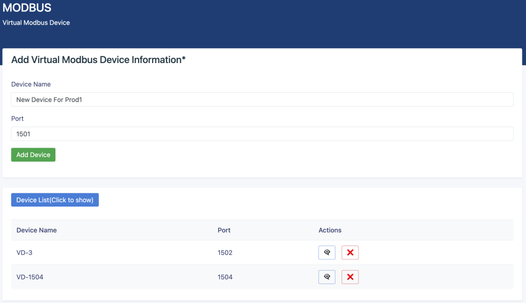
All existing virtual devices can be shown by clicking the blue button. You can also find out what is the physical device mapping to a virtual device by simply clicking the “👁️🗨️” button. You can also remove a virtual device if there is no mapping in the data sets. You will receive an error and not be allowed to remove it if there is a mapping.
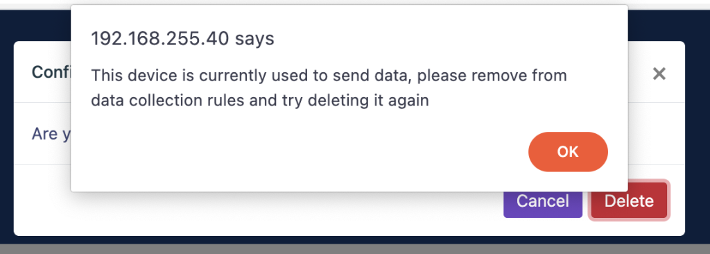
| Version Number | 23-1361-G |
| Release Date | 4.12.2023 |
| Fixed Bugs | None |
| New Features | OPC Data Transfer functionality has added with single instance |
| Version Number | 23-1314-B |
| Release Date | 6.08.2023 |
| Fixed Bugs | None |
| New Features | Modbus functionality nas improved to support 20 devices SQL table controls has added |
ConnexGate consist many software modules, that are working together to create a single system. All core modules are same for any connexGate models:
Select Monitor > Overview from the navigation tree to enter the overview page. As shown in Figure 2-1, The overview page is divided into 3 sections, namely "System Information", "Panel Port", and "Traffic".
Table 2-1: Basic Information configuration items
| Item | Description |
|---|---|
| Host Name | Displays the device name. Allows user to change it. |
| MAC Address | Displays the device’s MAC address. |
| Hardware Version | Displays the device’s hardware version. |
| Software Version | Displays the device’s software version. |
| Release Date | Displays the device software’s release date. |
| Product SN | Displays the device’s serial number. |
| CPU Used | Displays the device’s cpu status. |
| Memory Avail | Displays the device’s memory status. |
| System Uptime | Displays the time from last system start. |
The port statistics module displays statistics about the packets received and sent through
interfaces.
Displaying port statistics
Select Monitor > Port Statistics in the navigation area to enter the page shown in Figure 2-2. The page displays the port’s Rx Load, Tx Load, Speed, Under size, Over size, CRC Error, Collision Count. Table 2-2 describes the items of port statistics.
The “Loop Protection” page is used to display the working status of device loop-related protocols, such as ERPS and Spanning Tree protocols.
The "Serial Server State" page is used to display the working status of Serial Server.
Table 2-3: Items of Serial Server
| Item | Description |
|---|---|
| ID | Serial port ID number of the serial port server |
| Net Octets Rx | The number of bytes received by the network |
| Net Packets Rx | The number of packets received by the network |
| Net Octets Tx | The number of bytes sent by the network |
| Net Packets Tx | The number of packets sent by the network |
| Serial Octets Rx | The number of bytes received by the serial port |
| Serial Packets Rx | The number of packets received by the serial port |
| Serial Octets Tx | The number of bytes sent by the serial port |
| Serial Packets Tx | The number of packets sent by the serial port |
| Net Connect Up/Down times | Number of network connections |
| Serial Overload Drop Packets | Number of packets discarded by serial port overflow |
The "Security" page is used to display the working status of device security-related protocols, with three parts: port security, IP Source Guard, and MAC authentication.
The " PoE State" page is used to display the current PoE working status of the device. (1) Select Monitor > PoE State in the navigation bar to enter the PoE status page, as shown in Figure 2-8.
(2) On the current page, you can see the total power supply of the device, the number of power supply ports, and the power supply status of each port. Specific parameter descriptions are shown in Table 2-4.
The LLDP Status page is used to display the device LLDP working status.
The "IGMP Snooping State" page is used to display the working status of the device IGMP Snooping protocol.
The “DHCP Snooping State” page is used to display the working status of the DHCP Snooping protocol of the device.
The "QinQ Information" page is used to display the working status of the device QinQ information.
The "LoopDetect State" page is used to display the working status of the loop.
The "ARP Information" page is used to display the working status of the device ARP information.
MQTT is a publish-subscribe messaging protocol that operates on the client-server model. In this model, there are clients (devices or applications) that publish messages to a central server, known as the MQTT broker, and other clients that subscribe to specific topics of interest. When a message is published on a topic, the broker routes it to all subscribed clients. This decoupling of producers and consumers allows for efficient and asynchronous communication.
Where Is It Used?
MQTT is used in various industries and applications, primarily in IoT and M2M scenarios. Here are some common use cases:
| Protocol | Planned Timeframe |
|---|---|
| Multi node OPC | End of 2023 |
| MQTT initiation | January 2024 |
| Multiple video transfer | February 2024 |
| Advanced MQTT broker | April 2024 |
| Generic Web API connector | April 2024 |
General settings option allows to configure SNMP, NTP, Syslog protocol options and also creating the technical support file to be shared for support analysis.

This menu covers all SNMP related configuration items. SNMP protocol is used to retrieve device specific informations. Both SNMPv2 and SNMPv3 is supported, and provide same level of information. Both v2 and v3 access informations can be changed from this menu. Only information read is allowed via SNMP. Writing is not possible using any SNMP protocol.

Time synchronisation is important for log collection. Logs are generated and stored using system time, so accurate timing is important to match network wide log parsing. If NTP is not accessible or enabled, it is recommended to set system time manually from command line interface main menu.

System logs are generated and stored internally to analyse system behaviour and errors when needed. It is also possible to send the logs to a third party syslog receiver. Standard syslog messages are sent to system log collector. Syslog can be enabled from this menu, and it starts sending the logs as long as it is enabled.

This menu is used if you need to open a service request to Angora Networks. If you think there is a problem with device operation, you can access Angora Service Portal (click to open). You should send the tech support file while opening the service request. This will make the support procedures more efficient. Every time you click the “Create Tech Support File” button, Arrow creates a new encrypted file with full system logs. Download the file by clicking below button, and attach it into the service request.

Modbus is indeed a very old (late 1970s) protocol that was created for the communication between among programmable logic controllers, PLC. It is based on a master/slave relation. That means a device acting as master, polls slave devices to read or write information. Registers are data storage repository defined with a register reference address and are slave specific only. Old Modbus implementations are based on serial communication, but today with the spread of network based communication, Modbus also evolved to be operated on TCP/IP networks. Arrow supports TCP based modbus operations, so this document will be restricted to only network side of modbus protocol and focused on Arrow operation.
Similar to other client/server applications, modbus master sends out a request to slave address with a specific function code, register number and count. This requests inform the slave about information to be received by master. The request and response is very similar to each other and are in the following format.
| Device Address |
| Function Code |
| Register Number |
| Register Count |
| Data |
| Checksum |
There are different types of register. Function code defines what type of register information exchange will be triggered. The most common function belongs to the operation of “reading holding registers”, and it is 3 (three). This function allows the master to request one or more holding register stored values. Similarly code 16 is used to write into holding registers.
Arrow basic modbus process creates a simulated modbus network by starting virtual devices on Postman side. Every PLC would have its shadow copy on unrestricted network, allowing data stored in the actual PLC device to be accessible by business or reporting tools while keeping it safe from tampering.
Arrow Guardian is responsible with reading data from individual modbus slaves, encapsulate into a transferrable format and send it to Postman from the fiber interconnection. Last information is stored in Postman memory for a period of refresh time interval defined in Guardian IOT settings menu. Neither Guardian nor Postman writes the retrieved information into a permanent datastore, preventing any data leak. Data requester ask register informations from Postman using standart Modbus protocol. If Guardian stops sending information for one modbus slave, Postman also stops providing this information and return relevant error codes.
In case a virtual PLC device is removed from rule sets defined in Guardian “Data Collect” menu, this virtual device will be removed from Postman and unaccessible error code would return if any receiver tries to ask information from this virtual device.
You can create up to 20 virtual devices per pair. This number will be increased in following versions.
ConnexOne devices are bundled together with fiber transceivers and power supplies. Both devices are factory configured to work with each other only. Fiber transceivers are also mapped to their relevant devices.
ConnexOne consist of a Guardian and Postman devices. Guardian device is designed to be in the data generated network side, while Postman should reside in data transfered side which is usually open to public access.
There are six copper ethernet ports on each device. On the Guardian device, First four (4) ports (1,2,3,4) are reserved for network use. One can use any of the four ports or all of them to get connected into restricted networks. Currently port aggregation technologies are not supported. 4 ports are configured to act as a network switch with spanning tree protocol already enabled. All ports should reside in the same vlan, otherwise ports would interconnect vlans configured on connected side. On the Postman device, last four (4) ports (3,4,5,6) are configured to access network, with same switching functionalities and restrictions.
Fiber transceivers are designed to work on their relevant devices. The label on the transceiver explains where to use them. TX transceiver must be plugged into Guardian SFP1 port and RX receiver must be plugged into Postman SFP1 port. SFP2 ports on each device are not functional and reserved for future use. Fiber ports should be connected by a single core multi mode fiber cable. Cable should be plugged into left eye of Guardian SFP and right eye of Postman SFP as shown in the following figure.
ConnexOne pairs shipped with two 12V AC adapter. It is strictly recommended to use their original adapter. The adapters equipped with a ring connector that helps the adapter connection to be as strong as possible and not disconnect in case of human intervention.
The devices are powered automatically when the adaptor is connected into power. All SFP and fiber connections should be made prior to powering devices. Below is an example of both device connection
Please check next section “First Boot” for initial configuration
Documentation for ConnexGate OT/ICS security gateway and firewall.
OT/ICS › Security
Sections below mirror the table of contents from the source site.
connexGate is an operation technologies focused protocol and security gateway, providing secure access to backend data from PLC, IoT sensors, RTU and other OT data generators.
Product family consists of many different hardware flavors, with different performance level, interface density and physical characteristics.
This document describes detailed product features and provide guidance for administrative user to configure and maintain any connexGate appliance. Configuration examples and methods explained in this document is based on connexGate 102 hardware and 1.0.2 software version, although most of the information are valid for other models and versions
connexGate is a web-based Operational Technology (OT) gateway management platform designed to provide secure and controlled access between OT networks and PLC/IoT devices. The system operates with dual network interfaces, enabling controlled communication between networks while providing security, monitoring, and protocol translation capabilities.
ConnexGate consist many software modules, that are working together to create a single system. All core modules are same for any connexGate models:
ConnexGate administration user interface is built on everyday look and feel frameworks that most user experience while browsing usual internet.
UI elements and functions used in UI are as follow;
The connexGate interface consists of;
This is the welcoming page and provides a high-level overview of system status, device information, and key metrics. In cases you browsed to other pages and need to return the dashboard, simply click "Dashboard" in the sidebar navigation.
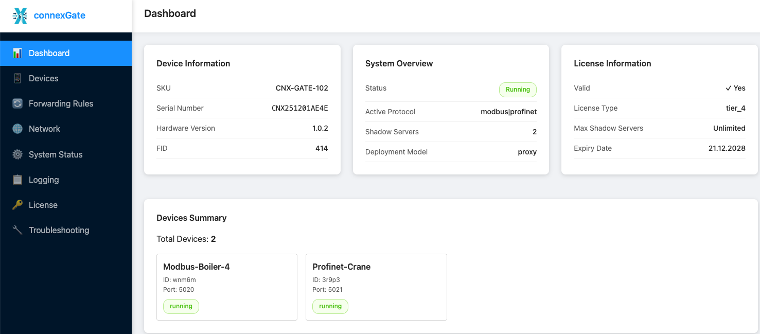
There are different cards with key informations:
Key Information Displayed:
ConnexGate allows collection of data from any real device and protecting them from attacks that may be harmful for operational purposes.
Think about a real PLC device providing information to an HMI screen, without any security measures applied due to mismanagement, protocol nature or subjected to administrative abuse. Any harmful attack may take the PLC out of service, change its parameters or apply some write commands that would eventually interrupt or broke operation, or disturb machine configuration or calibration.
ConnexGate is positioned in front of the PLC/Sensor/RTU devices, and serves as the shadow of the actual device, providing same registers/tags. This makes any attack would be defended and absorbed by connexGate, preventing any operational loss and trigger alarms to inform administrators.
Shadow devices are here to reflect and update the real values read from actual devices. You can use the same register/datablock or start from zero for each shadow. Also it is possible to create more than one shadow per real device, spreading different information on separate shadows.
**Shadow Architecture**
To create a shadow device, first click "Devices" in the sidebar navigation. Proxy model must be enabled in license.
Shadow module implements a server architecture for protocol-aware proxying. Each configured device has a corresponding server that:
**Adding a Shadow Device**
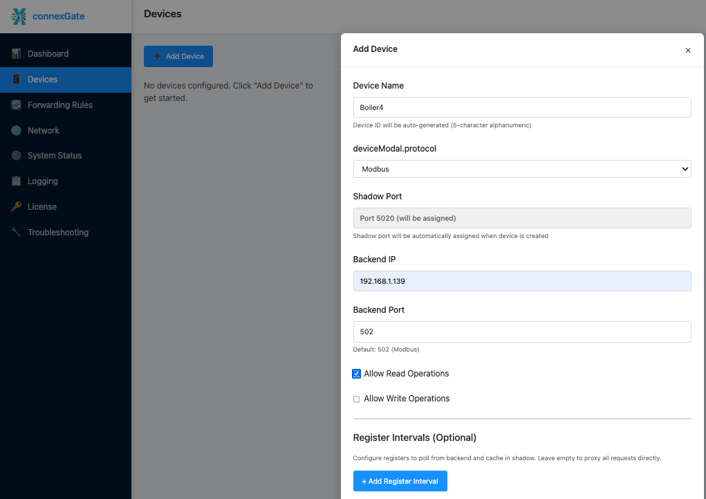
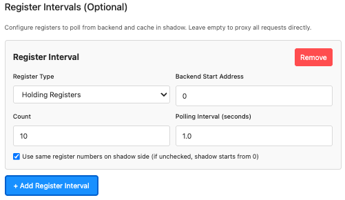
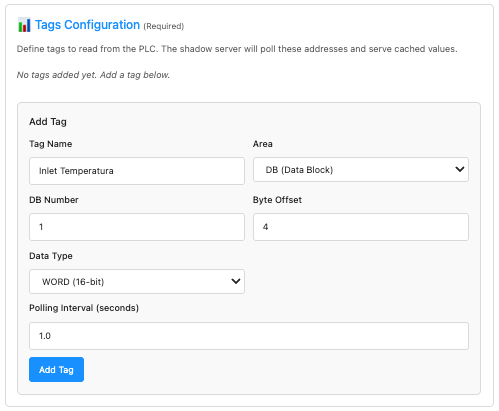
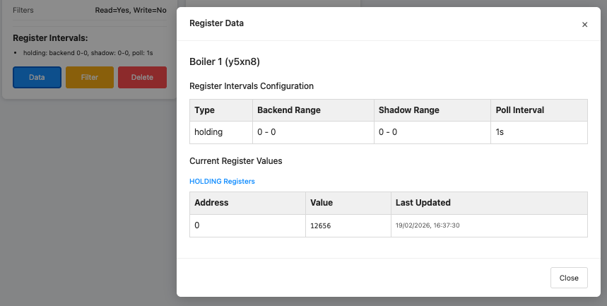
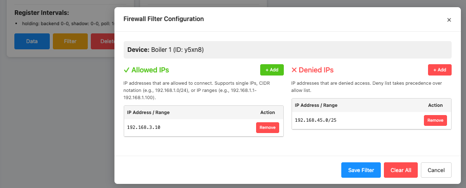
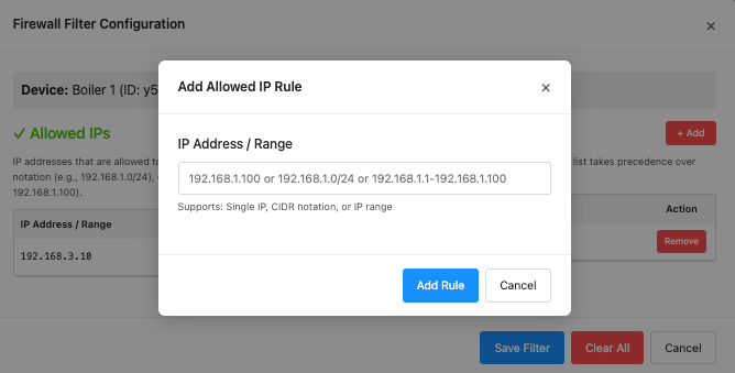
Delete button is self explained, and show a confirmation dialog to delete a shadow server
Devices display status indicators shows either
Device Limits
The system enforces license-based device limits. If the maximum number of devices is reached, you should delete an existing device before adding a new one.
Another deployment model of ConnexGate is to forward requests without any connection termination. This method allows sessions to be forwarded to backend PLC/Sensor/RTU device. Although this method is not providing same level of security with shadow servers, its easy of deployment helps real devices to be reachable within seconds. Even there is no session termination in this mode, ConnexGate still logs the requests and information returned from real device, providing detailed logs for remote collection and analysis.
**Forwarding Architecture**
To create rules for backend device forwarding, you should click the “Forwarding Rules” menu item. NAT model must be enabled in license in order to configure new rules.
Forwarding engine implements stateless port forwarding for transparent traffic flow between networks. Current implementation is configured to forward traffic from OT side to PLC side, allowing any SCADA or similar systems to be able to retrieve data as they are usually running.
Forwarding policy requires an IP address from the OT network interface IP range, to accept connections, and forward this request to any device on the PLC networks. Translation makes the requester IP seen as the ConnexGate PLC interface IP. Users can create separate translation rules, no matter backend real device is single or more.
To configure a forwarding rule, click on the “Add Forwarding Rule” button on the top right of the forwarding rules page.

This would open a configuration modal, to enter all information needed for traffic flow. Users should fill all fields where only description is optional:
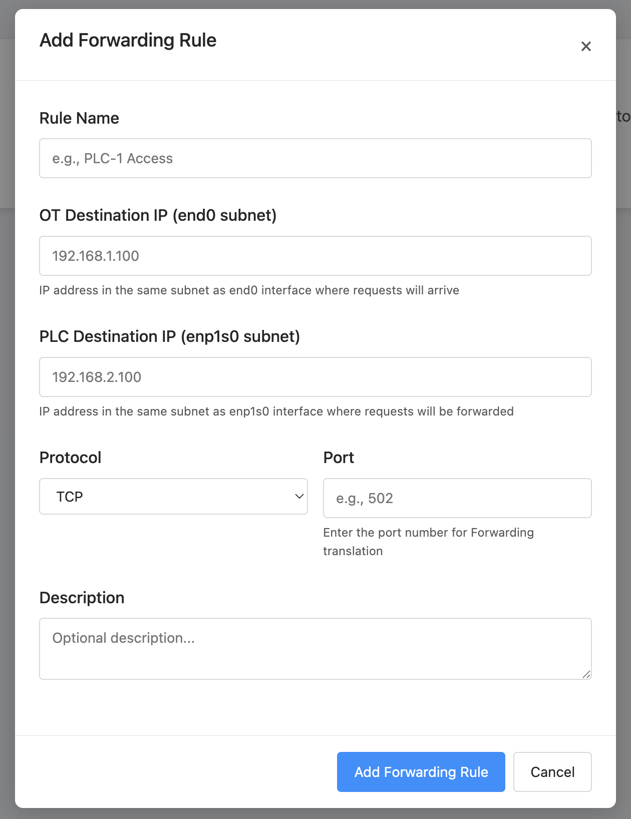
**How NAT Rules Work**
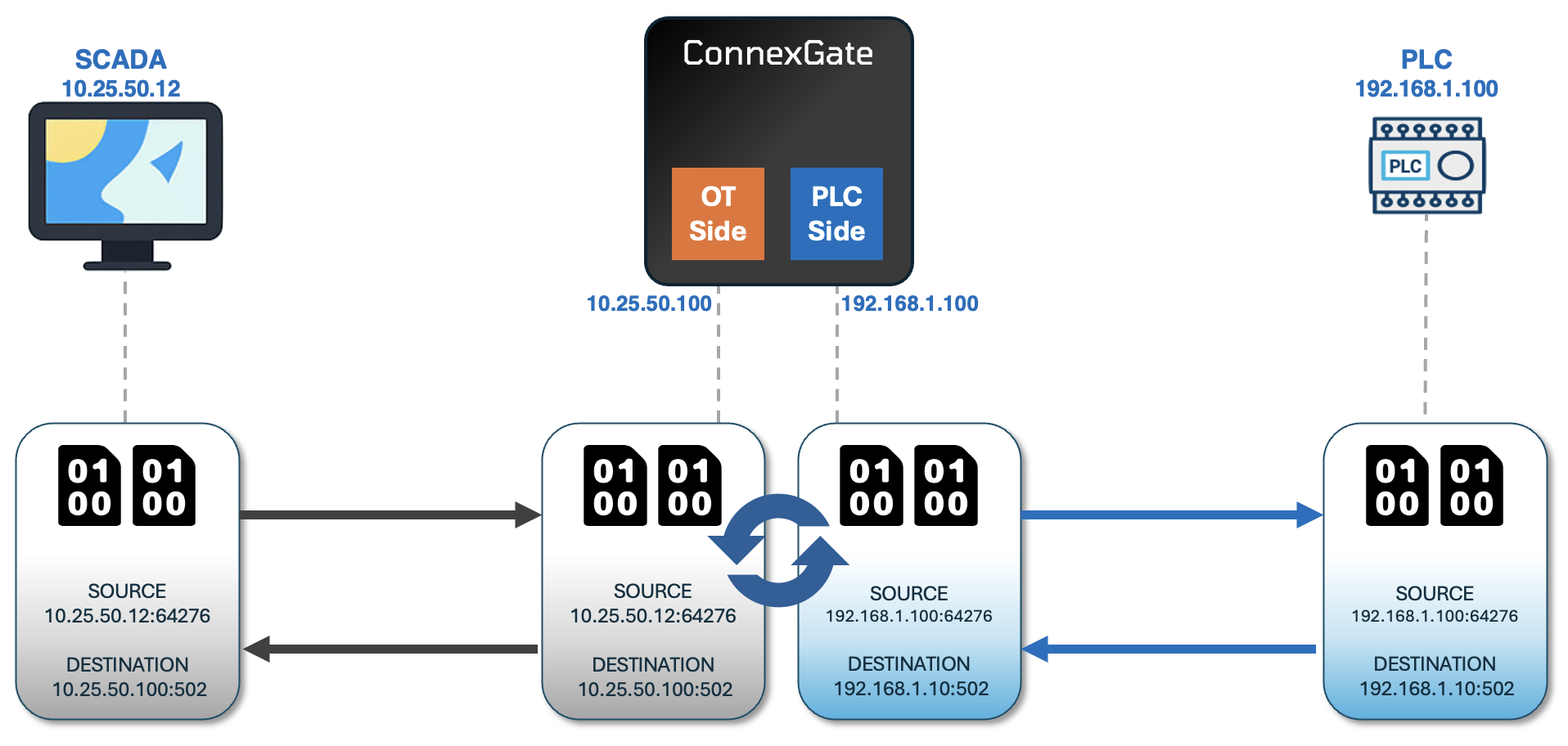
A typical forwarding scenario is running with the following steps:
Requester initates the connection with its own IP as source and ConnexGate OT side IP as destination.
Upon receiving ConnexGate translate the source IP to its PLC side interface IP and destination IP to PLC address.
ConnexGate sends out packets from PLC side interface.
PLC receives the packets as if they arrive from ConnexGate, and reply to ConnexGate PLC IP
ConnexGate receives the reply, change the source IP to its OT side interface IP, desination IP to original requester IP, and sends out from OT side interface.
This scenario is mostly applied where actual PLC IP address cannot be changed or where there are many PLC with the same IP addresses. Using ConnexGate would allow packet transmissions, without requiring any change on PLC configuration. Which is often very hard if not impossible.
There are two physical interfaces on ConnexGate (some devices may have different port configurations). Usually these two interface would face to OT network and PLC network. ConnexGate also support VPN configuration (currently only Wireguard is supported) that would allow it to be accessible from remote sites.
Clicking "Network" in the sidebar navigation would open the network settings page.
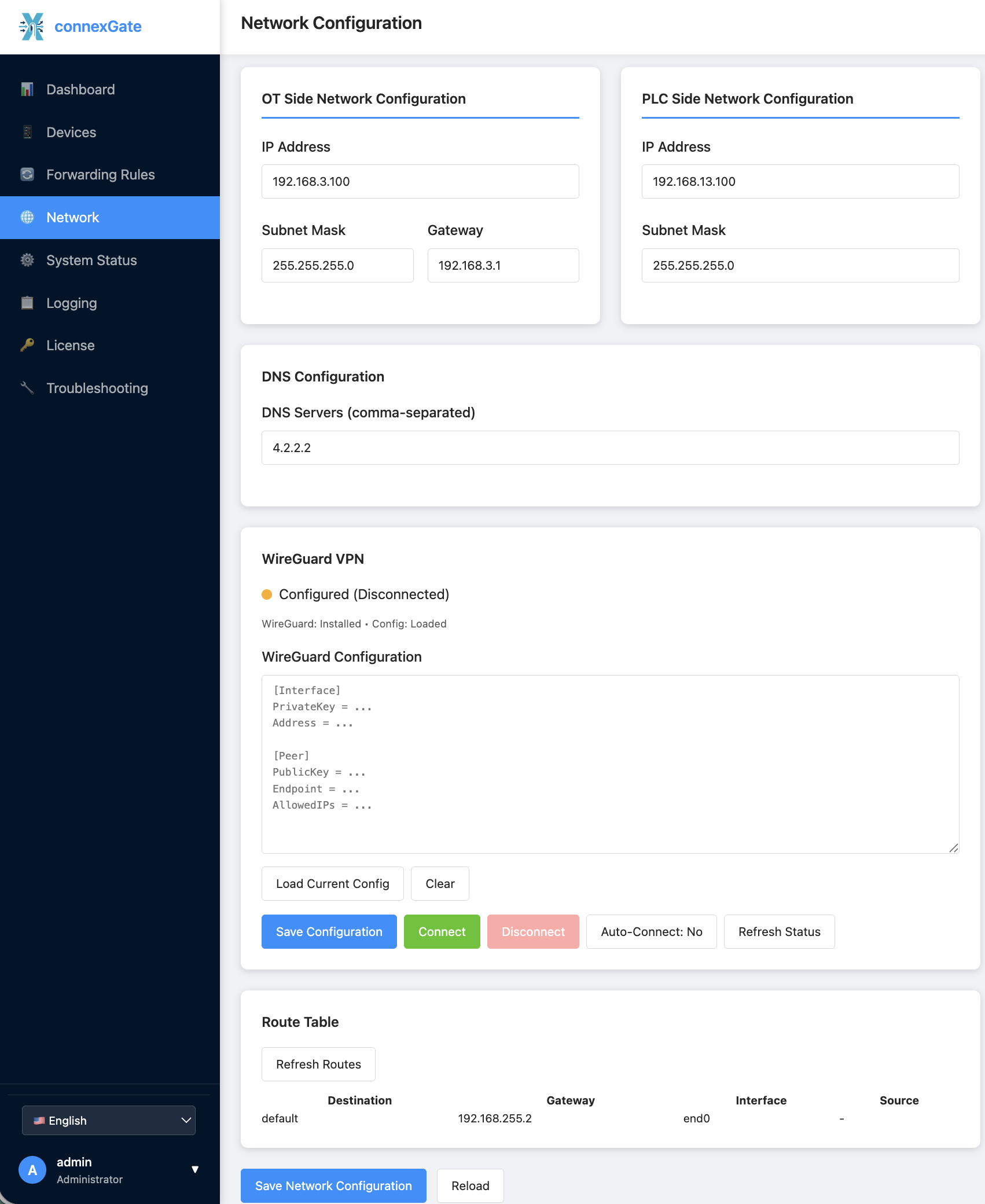
OT and PLC side configuration should be properly configured first, before creating any shadow device or forwarding rules. Any change in network configuration is instantly applied when clicked to “Save Network Configuration” button.
!!! Administration interface is accessible from interface addresses. If you change interface addresses, you should reconnect to administration interface using new ip address. New URL would be https://<new_ip_address>:8080
**Network Configuration**
Network configruation fileds in the network page are mostly self-explained
OT Side Configuration:
PLC Side Configuration:
DNS Configuration:
**VPN Configuration**
ConnexGate is supporting Wireguard as VPN connectivity. OpenVPN and IPSec support would be added in the upcoming releases.
VPN connectivity would be important, if backend PLC devices would be managed remotely. Since many OT protocol lacks proper encryption, VPN usage would be very important on remote connections.
Users should copy their Wireguard configuration into the “Wireguard Configuration” box. Clicking “Save Configuration” would install the wireguard configuration for permanent use.
Configuration is not activated automatically. User should click “Connect” button to activate the tunnel. There is an “Auto Connect” button to restore the connection in case of any failure, such as remote server failure, power shortage or wide area access.
System Status page show raw system information, network interface status, protocols, active shadows and system health. This page is showing raw data, retrieved from core modules directly. These information is important while troubleshooting or opening a service request. .
Information Displayed:
ConnexGate provides detailed logs of all requests to shadow servers and requests forwarded to backend devices.
The Logging system provides multi-layered logging capabilities
**Firewall Logs**
Firewall log table consist of following items with filtering options
**Request Logs**
Request log table consist of following items with filtering options
Features:
**Remote Logging**
Logs created in ConnexGate would be sent out to a remote collector using syslog or mqtt protocols.
**Logging Settings**
Purpose: Configure remote logging to Syslog and MQTT brokers.
Syslog Configuration:
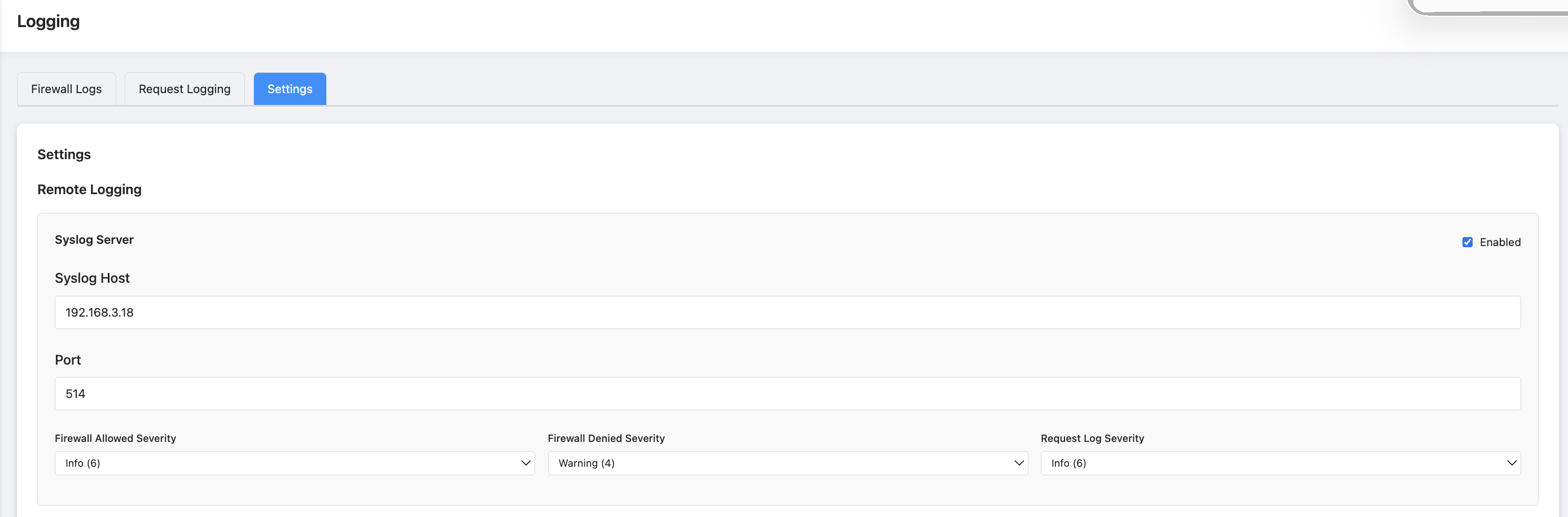
MQTT Configuration:
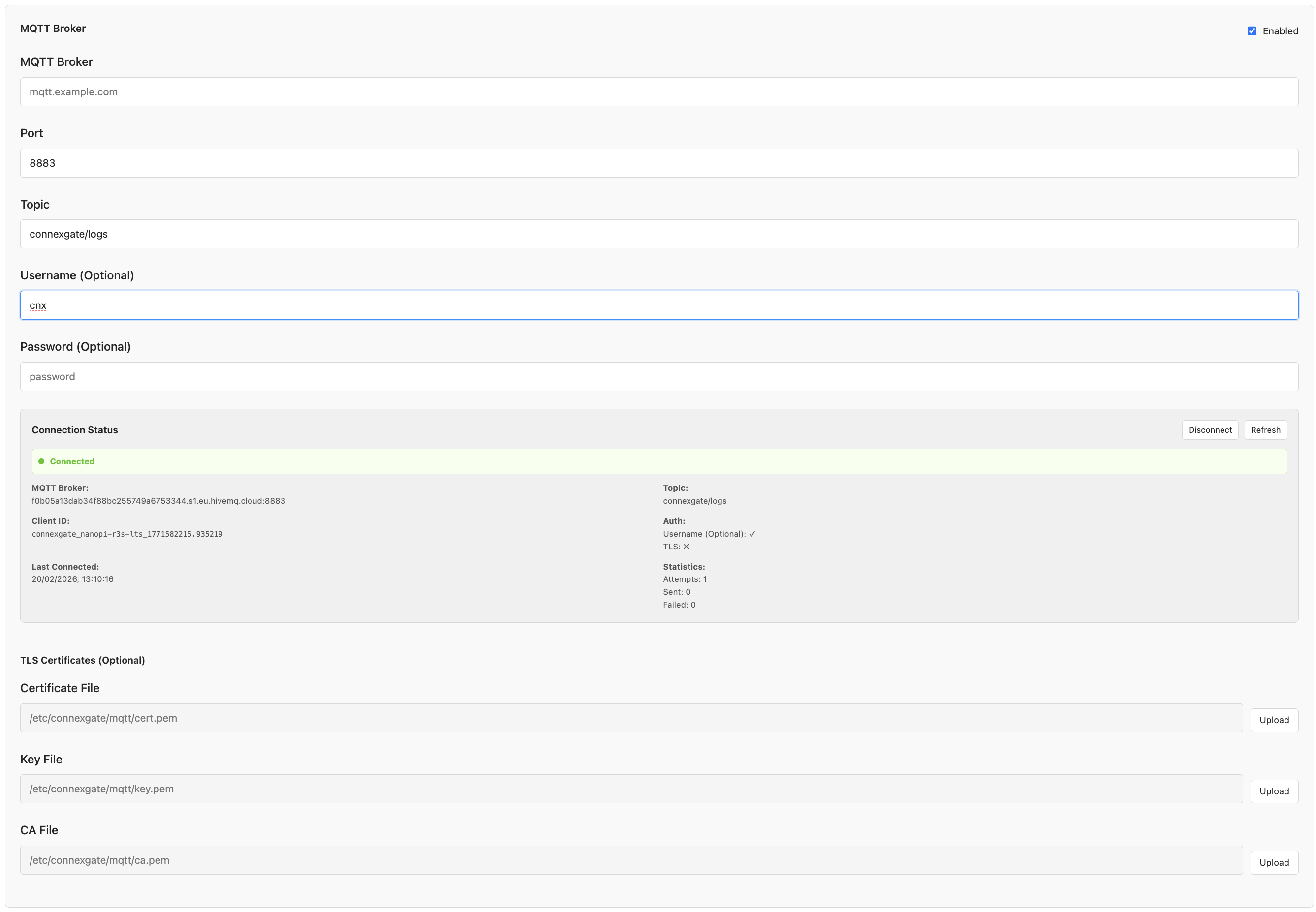
MQTT Status Information:
Saving Settings:
Purpose: View license information, activate licenses, and manage device keys.
Access: Click "License" in the sidebar navigation.
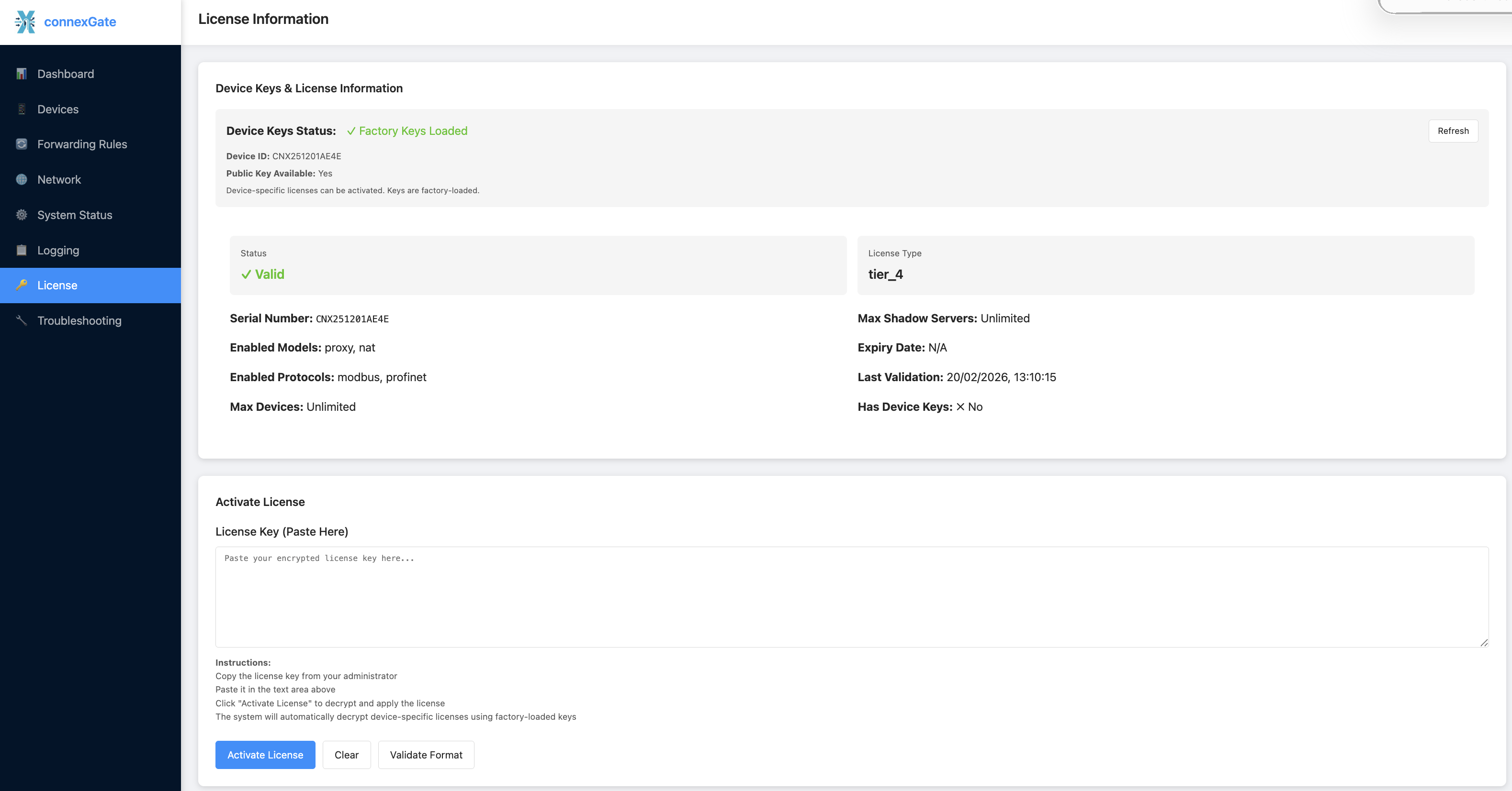
Technical Implementation
The License Management system implements a cryptographic license validation system:
License Information
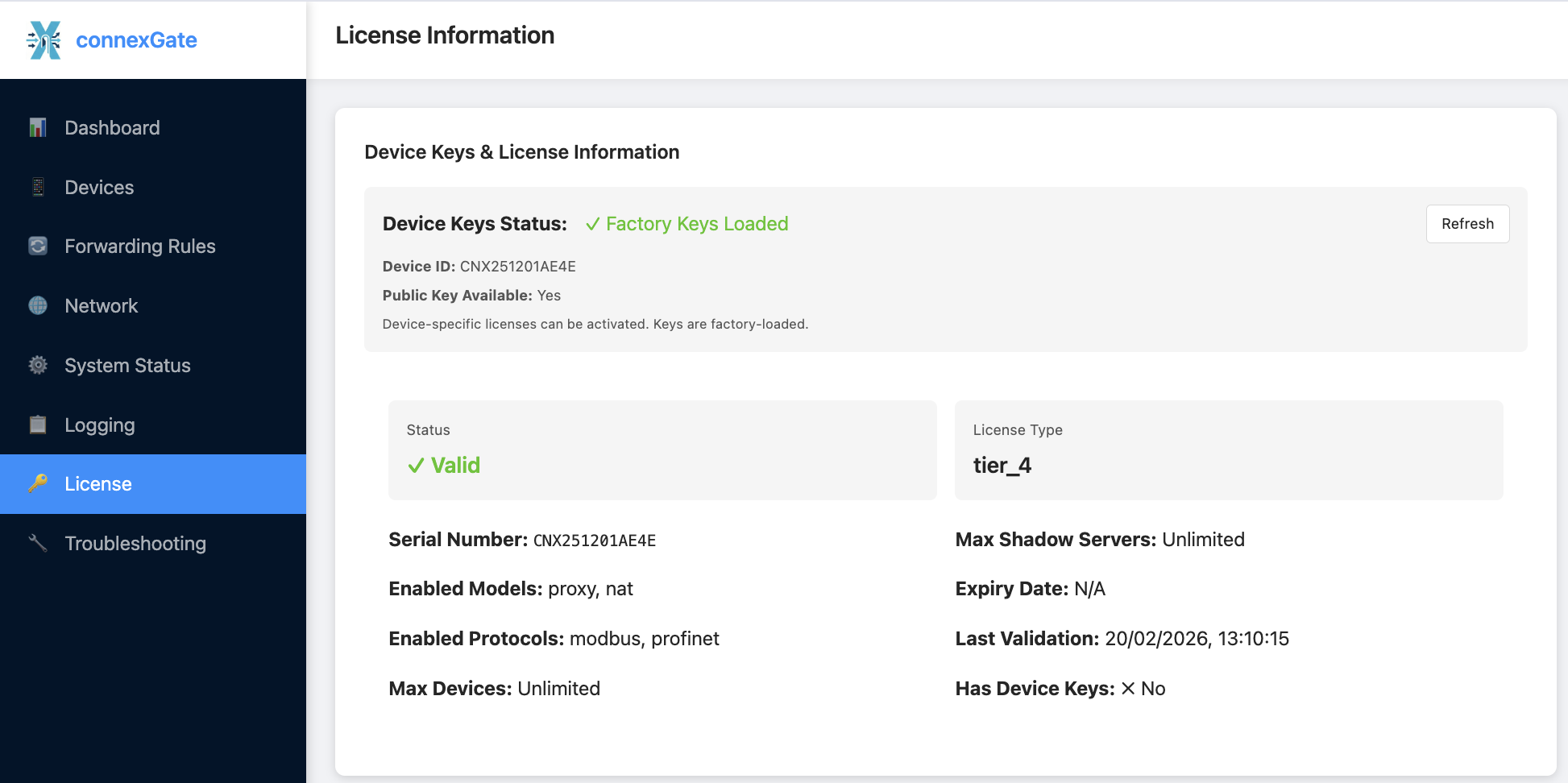
Displayed Information:
Device Keys Status
Status Indicators:
Reload Keys: Button to reload device keys from disk (useful if keys were generated after application startup).
Activating a License
Method 1: Request from License Server
Method 2: Activate with License Key
After Activation:
ConnexGate troubleshooting options provide tools to check network connectivity and packet flows, to diagnose network related issues and control proper delivery of packets for detailed analysis.
Clicking "Troubleshooting" in the sidebar navigation would show two tab for ping and packet capture tools.
**Ping Tool**
Ping tool is used to test network connectivity to hosts. This is the default tab for troubleshooting section:
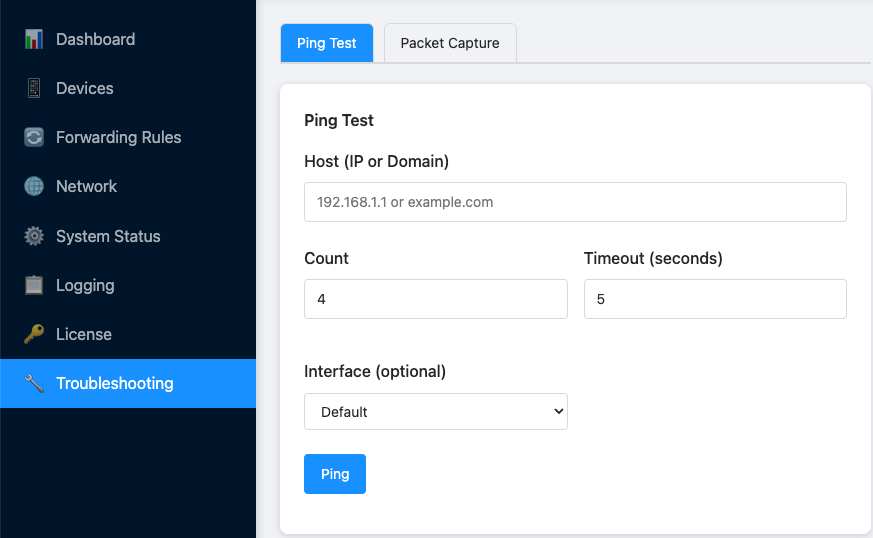
To start a ping test;
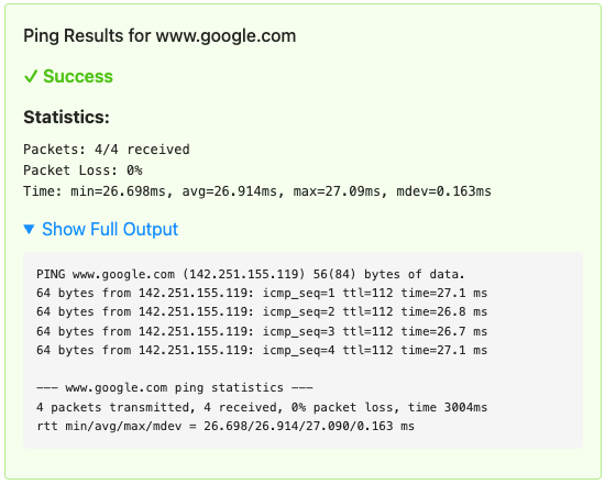
**Packet Capture**
This tab is used to capture network packets for analysis:
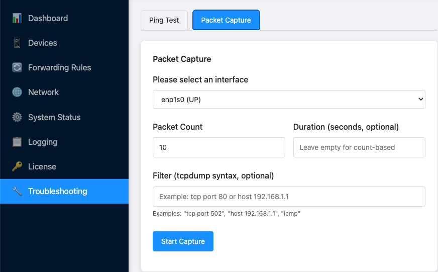
To start a capture session
OT (Operational Technology): Hardware and software systems that monitor and control physical devices and processes in industrial environments.
SCADA (Supervisory Control and Data Acquisition): System architecture for monitoring and controlling industrial processes.
PLC (Programmable Logic Controller): Industrial computer used for automation and control.
Shadow Server: Virtual server that mimics a real PLC, proxying requests to the actual device while applying security filters.
NAT (Network Address Translation): Method of remapping IP addresses and ports for routing traffic between networks.
Modbus: Industrial communication protocol for connecting electronic devices.
Profinet: Industrial Ethernet standard for automation.
S7: Siemens S7 communication protocol used in Profinet systems.
DCP (Discovery and Configuration Protocol): Profinet protocol for device discovery and configuration.
ACL (Access Control List): List of permissions defining access rights for IP addresses.
CIDR (Classless Inter-Domain Routing): Notation for IP addresses and routing (e.g., 192.168.1.0/24).
JWT (JSON Web Token): Compact token format for secure information exchange.
Syslog: Standard protocol for message logging.
MQTT (Message Queuing Telemetry Transport): Lightweight messaging protocol for IoT.
Log Rotation:
License Validation:
Configuration Backup:
Certificate Renewal (if using SSL/TLS):
Service Management:
bash sudo systemctl status connexgate
sudo systemctl start connexgate
sudo systemctl stop connexgate
sudo systemctl restart connexgate
sudo journalctl -u connexgate -f
Network Interface Verification:
bash ip addr show
ip link show
ping <target-ip>
"Proxy engine not available":
"NAT engine not available":
"Maximum number of shadow servers reached":
"Failed to connect to license server":
"Device keys not found":
"Network interfaces validation failed":
Storm control prevents traffic on a LAN from being disrupted by a broadcast, multicast, or unicast storm on one of the physical interfaces. A LAN storm occurs when packets flood the LAN, creating excessive traffic and degrading network performance. Errors in the protocol-stack implementation, mistakes in network configurations, or users issuing a denial-of-service attack can cause a storm.。 Storm control uses bandwidth as a percentage of the total available bandwidth of the port that can be used by the broadcast, multicast, or unicast traffic, to measure traffic activity. because of hardware limitations and the way in which packets of different sizes are counted, threshold percentages are approximations.
SWITCH(config-if)#storm-control {broadcast | multicast | unicast | all | unicast-broadcast | multicast-broadcast} level LINESWITCH(config-if)#no storm-controlConfigure broadcast, multicast, or unicast storm control. By default, storm control is disabled. If you set the threshold to the maximum value (100 percent), no limit is placed on the traffic. If you set the threshold to 0.0, traffic on that port is blocked. The range is 0.00 to 100.00. Support adaptive port rate change. Unicast only containing unknown unicast packets.
Example 1:Configure the unknown multicast storm control on port gigabitEthernet0/1 to 10% of the total bandwidth. Step 1: Specify the interface gigabitEthernet0/1 to be configured, and enter interface configuration mode.
SWITCH#SWITCH#configure terminalEnter configuration commands, one per line. End with CNTL/Z.
SWITCH(config)#interface gigabitEthernet0/1SWITCH(config-if)#Step 2: Configure the unknown multicast storm control on port gigabitEthernet0/1 to 10%.
SWITCH(config-if)#storm-control multicast level 10SWITCH#show storm-controlGiE0/1 100.00% 10.00% 100.00% GiE0/2 100.00% 100.00% 100.00% GiE0/3 100.00% 100.00% 100.00% GiE0/4 100.00% 100.00% 100.00% GiE0/5 100.00% 100.00% 100.00% GiE0/6 100.00% 100.00% 100.00% GiE0/7 100.00% 100.00% 100.00% GiE0/8 100.00% 100.00% 100.00% GiE0/9 100.00% 100.00% 100.00% GiE0/10 100.00% 100.00% 100.00% GiE0/11 100.00% 100.00% 100.00% GiE0/12 100.00% 100.00% 100.00%
Network setting page allows you to change IP address parameters and monitor interface traffic. You can find all network related information in the front page.


You can change the IP address of Arrow device from this menu. The changes will be applied momentarily and you may lose accedd to user interface for some time. You should re-enter the web interface with the new address. All services will use the new IP address, so if you are using other network devices to operate Arrow devices such as firewalls, you should update your policies.
This section shows interface received and sent traffic information for the last 60 minutes. There are basically two interface in each device. Network Interface is the bridge interface to receive requests into Guardian, and to sent to out information from Postman to public network. Transfer interface is the fiber connected interface between to Arrow devices.

Arrow is designed to be user and administrator friendly. There are simple menus and straightforward management options both for the platform itself and functions. This section covers platform settings. For advanced protocol settings, refer to the relevant protocol guides.
Here is the initial screen after login:

General settings option allows to configure SNMP, NTP, Syslog protocol options and also creating the technical support file to be shared for support analysis.
This menu covers all SNMP related configuration items. SNMP protocol is used to retrieve device specific informations. Both SNMPv2 and SNMPv3 is supported, and provide same level of information. Both v2 and v3 access informations can be changed from this menu. Only information read is allowed via SNMP. Writing is not possible using any SNMP protocol.
Time synchronisation is important for log collection. Logs are generated and stored using system time, so accurate timing is important to match network wide log parsing. If NTP is not accessible or enabled, it is recommended to set system time manually from command line interface main menu.
System logs are generated and stored internally to analyse system behaviour and errors when needed. It is also possible to send the logs to a third party syslog receiver. Standard syslog messages are sent to system log collector. Syslog can be enabled from this menu, and it starts sending the logs as long as it is enabled.
This menu is used if you need to open a service request to Angora Networks. If you think there is a problem with device operation, you can access Angora Service Portal (click to open). You should send the tech support file while opening the service request. This will make the support procedures more efficient. Every time you click the “Create Tech Support File” button, Arrow creates a new encrypted file with full system logs. Download the file by clicking below button, and attach it into the service request.
Network setting page allows you to change IP address parameters and monitor interface traffic. You can find all network related information in the front page.
You can change the IP address of Arrow device from this menu. The changes will be applied momentarily and you may lose accedd to user interface for some time. You should re-enter the web interface with the new address. All services will use the new IP address, so if you are using other network devices to operate Arrow devices such as firewalls, you should update your policies.
This section shows interface received and sent traffic information for the last 60 minutes. There are basically two interface in each device. Network Interface is the bridge interface to receive requests into Guardian, and to sent to out information from Postman to public network. Transfer interface is the fiber connected interface between to Arrow devices.
Arrow web UI is accesible via both HTTP and HTTPS. It is highly recommended that you use certificate secured HTTPS connection, to access and configure devices.
Arrow comes with a pre-installed SSL certificate. In case you want to renew the certificate, you can use HTTPS settings menu and update the certificate with new identifier informations as follow:

Once you click to the “Generate Self Signed SSL Certificate”, a new certificate will be issued, and you will be asked to restart the service. We leave the restart operation to administrators, as the service restart would interrupt web services for couple of seconds. No other services is affected by this operation. A new button would appear to restart the service and activate the new certificate.

MQTT (Message Queuing Telemetry Transport) is a publish-subscribe messaging protocol that operates on the client-server model. It’s designed for efficient and lightweight communication, making it ideal for scenarios where low bandwidth, high latency, or unreliable network connections are common. Here’s a detailed explanation of how MQTT works:
1. MQTT Clients:
2. MQTT Broker:
3. Topics:
4. Publishing Messages:
5. Subscribing to Topics:
6. Quality of Service (QoS):
7. Retained Messages:
8. Last Will and Testament (LWT):
In summary, MQTT provides a flexible and efficient way for devices and applications to communicate in a decoupled and asynchronous manner. Clients publish messages to topics of interest, and the broker ensures the delivery of these messages to subscribed clients, all while offering various levels of message delivery assurance and support for retained messages and last will messages. MQTT’s lightweight design and versatility have made it a popular choice for IoT, M2M, and other applications with constrained resources or challenging network conditions.
Currently there is no hardware planned for 2023. New hardware options will be available for 2024. Please add this page into your bookmarks to check for latest updates
Thanks for getting your Arrow pair. This section describe all processes needed to jumpstart your devices. Please follow sub sections to start with Arrow devices.
ConnexOne devices are bundled together with fiber transceivers and power supplies. Both devices are factory configured to work with each other only. Fiber transceivers are also mapped to their relevant devices.
ConnexOne consist of a Guardian and Postman devices. Guardian device is designed to be in the data generated network side, while Postman should reside in data transfered side which is usually open to public access.
There are six copper ethernet ports on each device. On the Guardian device, First four (4) ports (1,2,3,4) are reserved for network use. One can use any of the four ports or all of them to get connected into restricted networks. Currently port aggregation technologies are not supported. 4 ports are configured to act as a network switch with spanning tree protocol already enabled. All ports should reside in the same vlan, otherwise ports would interconnect vlans configured on connected side. On the Postman device, last four (4) ports (3,4,5,6) are configured to access network, with same switching functionalities and restrictions.
Fiber transceivers are designed to work on their relevant devices. The label on the transceiver explains where to use them. TX transceiver must be plugged into Guardian SFP1 port and RX receiver must be plugged into Postman SFP1 port. SFP2 ports on each device are not functional and reserved for future use. Fiber ports should be connected by a single core multi mode fiber cable. Cable should be plugged into left eye of Guardian SFP and right eye of Postman SFP as shown in the following figure.
ConnexOne pairs shipped with two 12V AC adapter. It is strictly recommended to use their original adapter. The adapters equipped with a ring connector that helps the adapter connection to be as strong as possible and not disconnect in case of human intervention.
The devices are powered automatically when the adaptor is connected into power. All SFP and fiber connections should be made prior to powering devices. Below is an example of both device connection
Please check next section “First Boot” for initial configuration
ConnexOne devices are running on a Linux based server operating system, which provides enough capabilities to operate with underlying hardware platforms. Upon powering up, operating system starts loading. It takes around 2-3 minutes to boot completely.
Console port on the front panel should be used to connect device command line interface. Although standart UART console cables can be used to provide CLI access; Connexite console cables (SKU: CNX-CBL-USB-CNSL) are recommended.
Serial connection parameters to access into the devices are following:
| Baud Rate | Data Bits | Parity | Stop Bits | Flow Control |
|---|---|---|---|---|
| 115200 | 8 | None | 1 | None |
Factory default username is admin, and the password is connexite
Upon successful login, a welcome prompt will be shown.
Welcome to the Connexite ConnexOne Data Diode - Postman  Initial Setup Menu!
Press Enter to start.
Pressing enter will show the main menu:
===== Main Menu =====
1. Configuration Menu
2. Status Menu
3. Exit

======================
Enter your choice:
Menu names are self descriptive. Only very basic configuration is handled from this menu. All other configurations related with ConnexOne operation would be done via web user interface. To configure device IP address, select (1) to enter configuration menu, (1) to select change IP address option, (1) to select br0 interface. Enter new IP address, subnet mask, gateway and nameserver. If you enter all these informations in correct format, IP address would change with the informations entered:
===== Configuration Menu =====
1. Change IP address
2. Change hostname
3. Change date and time
4. Change admin password
5. Back to Previous Menu
=============================
Enter your choice: 1
Change IP address
Select the interface to change IP address and add default gateway:
1. br0 (with default gateway)
Enter your choice: 1Enter the new IP address for br0: 192.168.255.40
Enter the new subnet mask for br0 (e.g., '16 or24'): 24
Enter the new gateway IP address for br0: 192.168.255.1
Enter the new nameserver IP address for br0: 192.168.255.1
Network config changing please wait...
IP address changed successfully for br0.
Press Enter to continue...You can now access ConnexOne user interface from https://<new_IP_address>

Although not mandatory for operation, you can also change the device hostname, date and admin password. It is strictly recommended to change the default admin password for CLI access. This password would also be used for remote secure shell access.
Web interface default username is also admin with the same password; connexite. Please keep in mind that shell admin password and web interface admin password are different and changing one does not affect the other. You should change both password separately. Web interface password can be changed from the relevant menu in the user interface. Please refer “Settings Management” document for the details.
3.1.1 Introduction Ethernet is a network technology based on the Carrier Sense Multiple Access/Collision Detect (CSMA/CD) mechanism. As the medium is shared, collisions and excessive broadcasts are common on an Ethernet. To address the issue, virtual LAN (VLAN) was introduced. The idea is to break a LAN down into separate VLANs, that is, Layer 2 broadcast domains whereby frames are switched between ports assigned to the same VLAN. VLANs are isolated from each other at Layer 2. A VLAN is a bridging domain, and ll broadcast traffic is contained within it, as shown in Figure 3-1.
A VLAN is logically divided on an organizational basis rather than on a physical basis. For example, all workstations and servers used by a particular workgroup can be connected to the same LAN, regardless of their physical locations. VLAN technology delivers the following benefits:
You can create VLANs based on:
Because the Web interface is available only for port-based VLANs, this chapter introduces only port-based VLANs. 3.1.1.1 VLAN Mode Depending on the tag handling mode, the VLAN Mode of a port can be one of the following three:
An access port belongs to only one VLAN and usually connects to a user device.
A trunk port can join multiple VLANs to receive and send traffic for them. It usually connects to a network device.
A hybrid port can join multiple VLANs to receive and send traffic for them. It can connect either a user device or a network device.
A hybrid port is different from a trunk port in that:
3.1.1.2 Port link type
By default, VLAN 1 is the default VLAN for all ports. However, you can change the default VLAN for a port as required. When doing that, follow these guidelines:
3.1.1.3 Frame handling methods
Table 3-1: A port configured with a default VLAN handles a frame as follows:
| Port type | Actions (in the inbound direction) |
|---|---|
| Actions (in the outbound direction) | |
| Untagged frame | Tag the frame with the default VLAN tag. |
| • Receive the frame if its VLAN ID is the same as the default VLAN ID | • Drop the frame if its VLAN ID is different from the default VLAN ID. |
| Remove the default VLAN tag and send the frame. | |
| Trunk | Check whether the default VLAN is carried on the port: |
| • If yes, tag the frame with the default VLAN tag. | • If not, drop the frame. |
| • Receive the frame if its VLAN is carried on the port. | • Drop the frame if its VLAN is not carried on the port. |
| • Remove the tag and send the frame if the frame Carries the default VLAN tag. | • Send the frame without removing the tag if its VLAN is carried on the port but is different from the default one. |
| Hybrid | Send the frame if its VLAN is carried on the port. The frame is sent with the VLAN tag removed or intact depending on your configuration. |
3.1.2 Configuring VLAN 3.1.2.1 Creating VLAN
Table 3-2: Vlan configuration items
| Item | Description |
|---|---|
| ID | This field displays the ID of the VLAN |
| name | By default, the description string of a VLAN is its VLAN ID, such as VLAN 0002. |
| Members | Indicates that the port sends the traffic of the VLAN without removing the VLAN tag. |
| Edit | Click to enter the VLAN editing page |
| Add | Click to enter the VLAN adding page |
| Delete | Select the VLAN ID, click to delete |
3.1.2.2 Configuring Trunk Port
Table 3-3: The description of the Trunk configuration
| Item | Description |
|---|---|
| Mode | Access |
| Set the port’s default VLAN ID, only exist in access mode. | The trunk ports at the two ends of a link must have the same PVID. Otherwise, the link cannot properly transmit packets |
| Native Vlan | VLAN(Native Vlan), only exist in Trunk mode. |
| Allow VLANs | Select the VLANs that are allowed through the port. |
3.2.1 Port Configuration
You can use the interface management feature to view interface information, create/remove logical interfaces, change interface status, and reset interface parameters, as shown in Figure 3-6.
Configuring interface management
Table 3-4: Configuration items of Port
| Item | Description |
|---|---|
| Admin State | Shutdown/no shutdown the port. |
| Description | Set the description of a logical interface. |
| Port Mode | Set the port’s vlan mode, Access or Trunk |
| PVID/Native VLAN | Set the port’s PVID or Native VLAN. |
| Medium type | Set the medium type of the Combo ports |
| • RJ45:the mode of port is 10/100/1000BASE-T | • SFP:the mode of port is 1000BASE-X |
| Note: only for combo ports. | |
| Speed(copper) | Set the port’s transmission rate: |
| • 10: indicates 10 Mbps | • 100M:indicates 100 Mbps |
| • 1000M:indicates 1000 Mbps | • Auto: indicates auto-negotiation |
| Note: only for copper ports. | |
| Duplex(copper) | Set the port’s duplex mode: |
| • AUTO:indicates auto-negotiation | |
| • FULL:indicates full duplex | |
| • HALF:indicates half duplex | |
| Set the port’s mode | • 100BASE-FX:indicates the port mode is 100BASE-FX. |
| • 1000BASE-X:indicates the port mode is 1000BASE-X. | • 2500BASE-X:indicates the port mode is 2.5G BASE-X. |
| • 10G BASE-X: indicates the port mode is 10G BASE-X. | Note: only for fiber ports. |
| Autoneg(fiber) | Enables or disables port’s autoneg. |
| The auto-negotiation function needs to be enabled or disabled at the same | time as the peer end, otherwise a link failure will occur. |
| Note: only for fiber ports. | |
| Flow control | Enables or disables port’s Flow control. |
| MTU | Allows or forbids jumbo frames to pass through the port. Default length of packets is 46-1500 bytes. |
| Admin Shutdown | Shutdown/no shutdown the port. |
3.2.2 Port Extension 3.2.2.1 Rate Limiting Port-based rate limiting allows you to limit the speed at which network traffic is sent or received by a device that is connected to a port on your switch. Unlike 802.1p Quality of Service (QoS), port-based rate limiting does not prioritize information based on type. Rate limiting simply means that the switch will slow down traffic on a port to keep it from exceeding the limit that you set. If you set the rate limit on a port too low, you might see degraded video stream quality, sluggish response times during online activity, and other problems.
The best use of rate limiting is to keep low-priority devices that are connected to your switch from using too much of your bandwidth and slowing down your other connected devices. A combination of rate limiting and QoS can help you maximize your network’s efficiency and prioritize devices and activities.
Configuring Port Ratelimit
Table 3-5: Port Ratelimit Configuration items
| Item | Description |
|---|---|
| In CIR (kbps) | Specify the rate limit in the inbound direction (KBits). |
| In CBS (KB) | Specify the burst size in the inbound direction (KBits). |
| Out CIR (kbps) | Specify the rate limit in the outbound direction (KBits). |
| Out CBS (KB) | Specify the burst size in the outbound direction (KBits). |
3.2.2.2 Storm Control A traffic storm occurs when a large amount of broadcast, multicast, or unicast packets congest a network.
You can use the storm suppression function to limit the size of a particular type of traffic (currently broadcast, multicast and unknown unicast traffic) on a per-interface basis in Ethernet port view or port group view.
In interface or port group view, you set the maximum broadcast, multicast or unknown unicast traffic allowed to pass through an interface or each interface in a port group. When the broadcast, multicast, or unknown unicast traffic on the interface exceeds the threshold, the system discards packets until the traffic drops below the threshold.
Configuring the Storm Control
Table 3-7: Items of the storm control
| Item | Description |
|---|---|
| Type | Disabled |
| Selects the parameter used in broadcast suppression and sets its | value in the percentage box. |
| Multicast | Selects the parameter used in multicast suppression and sets its |
| value in the percentage box. | |
| Unicast | Selects the parameter used in unicast suppression and sets its |
| value in the percentage box. | |
| multicast-broadcast | Selects the parameter used in multicast and broadcast |
| suppression and sets its value in the percentage box. | |
| unicast-broadcast | Selects the parameter used in unicast and broadcast, |
| suppression and sets its value in the percentage box. | |
| All | Selects the parameter used in unicast and unicast, |
| broadcast, suppression and sets its value in the percentage box. | |
| Percentage (%) | Indicates the maximum percentage of traffic to the total |
| transmission capability of an Ethernet interface. |
3.2.2.1 Isolation Usually, Layer 2 traffic isolation is achieved by assigning ports to different VLANs. To save VLAN resources, port isolation is introduced to isolate ports within a VLAN, allowing for great flexibility and security.
Configuring an Isolation Group
3.2.3 Port Mirroring Port mirroring is to copy the packets passing through one or multiple ports (called source interface) to a port (called the destination interface) on the local device. The source interface is connected with a monitoring device. By analyzing on the monitoring device, the packets mirrored to the destination interface, you can monitor the network and troubleshoot possible network problems.
Figure3-13 A port mirroring implementation Creating a mirroring group
Table 3-8: Configuration items of creating a mirroring group
| Item | Description |
|---|---|
| Session | ID of the mirroring group to be created |
| Destination Interface | the monitor port for the mirroring group, there can only be one |
| Source Interface | mirroring ports for the mirroring group, there can be more than one |
3.2.4 Port Aggregation 3.2.4.1 Overview Link Aggregation Ethernet link aggregation, most often simply called link aggregation, aggregates multiple physical Ethernet links into one logical link to increase link bandwidth beyond the limits of any one single link. This logical link is called an aggregate link. It allows for link redundancy because the member physical links dynamically back up one another.
As shown in Figure 3-16, Switch A and Switch B are connected with three physical Ethernet links. These physical Ethernet links are aggregated into an aggregate link, Link aggregation 1. The bandwidth of this aggregate link can be as high as the total bandwidth of these three physical Ethernet links.
LACP
The IEEE 802.3ad Link Aggregation Control Protocol (LACP) enables dynamic aggregation of physical links. It uses link aggregation control protocol data units (LACPDUs) for exchanging aggregation information between LACP-enabled devices.
There are two link aggregation modes: dynamic and static. Dynamic link aggregation uses LACP while static link aggregation does not. A link aggregation group operating in static mode is called a static link aggregation group, while a link aggregation group operating in dynamic mode is called a dynamic link aggregation group. 3.2.4.2 Configuring an Aggregation Group
Configuration procedure:
Table 3-9: description of global configure item
| Item | Description |
|---|---|
| Equalize according to the destination MAC address and source MAC address | |
| dst-ip | Equalize according to the destination IP address |
| srt-ip | Equalize according to the source IP address |
| src-dst-ip | Equalize according to the destination IP address and source IP address |
| dst-port | Equalize according to the L4 TCP/UDP destination port number |
| src-port | Equalize according to the L4 TCP/UDP source port number |
| src-dst-port | Equalize according to the L4 TCP/UDP destination port number and source port number |
Table 3-10: description of Aggregation Member
Table 3-11: description of Aggregation port
| Item | Description |
|---|---|
| Aggregation | |
| The member ports of the Aggregation Port |
3.2.5 Port Violation During the use of the device, active or passive violations may occur on the switch port, such as port security violations, port flapping violations, port loop detection violations, etc. The port violation module is used to configure the recovery enablement and recovery time of the violating port, and displays the port's violation behavior.
Configuration procedure:
Select Configuration > Port > Port Violation in the navigation bar to enter the port violation global configuration interface, check the service that needs to be violated, turn on the automatic recovery button and configure the recovery time, click the Apply button to complete the configuration, such as Figure 3-40 is shown, and the global configuration parameters are shown in Table 3-13.
3.3.1 Overview Spanning Tree Protocol (STP) is a Layer-2 management protocol. It cannot only selectively block redundant links to eliminate Layer-2 loops but also can back up links.
Like many protocols, STP is continuously updated from Rapid Spanning Tree Protocol (RSTP) to Multiple Spanning Tree Protocol (MSTP) as the network develops.
For the Layer-2 Ethernet, only one active link can exist between two local area networks (LANs). Otherwise, a broadcast storm will occur. To enhance the reliability of a LAN, it is necessary to establish a redundant link and keep some paths in backup state. If the network is faulty and a link fails, you must switch the redundant link to the active state. STP can automatically activate the redundant link without any manual operations. STP enables devices on a LAN to:
Discover and start the best tree topology on the LAN.
Troubleshoot a fault and automatically update the network topology so that the possible best tree topology is always selected.
The LAN topology is automatically calculated based on a set of bridge parameters configured by the administrator. The best topology tree can be obtained by properly configuring these parameters.
RSTP is completely compatible with 802.1D STP. Like traditional STP, RSTP provides loop-free and redundancy services. It is characterized by rapid speed. If all bridges in a LAN support RSTP and are properly configured by the administrator, it takes less than 1 second (about 50 seconds if traditional STP is used) to re-generate a topology tree after the network topology changes.
STP and RSTP have the following defects:
STP migration is slow. Even on point-to-point links or edge ports, it still takes two times of the forward delay for ports to switch to the forwarding state.
RSTP can rapidly converge but has the same defect with STP: Since all VLANs in a LAN share the same spanning tree, packets of all VLANs are forwarded along this spanning tree. Therefore, redundant links cannot be blocked according to specific VLANs and data traffic cannot be balanced among VLANs.
MSTP, defined by the IEEE in 802.1s, resolves defects of STP and RSTP. It cannot only rapidly converge but also can enable traffic of different VLANs to be forwarded along respective paths, thereby providing a better load balancing mechanism for redundant links.
In general, STP/RSTP works based on ports while MSTP works based on instances. An instance is a set of multiple VLANs. Binding multiple VLANs to one instance can reduce the communication overhead and resource utilization. 3.3.2 Spanning Tree Configuring Global Configuration of the Spanning Tree
Select Configuration > Spanning Tree > Global Configuration in the navigation area to enter the Global Configuration page, as shown in Figure 3-20. Table 3-12 describes the Spanning Tree Global Configuration items.
Table 3-12: Spanning Tree Global Configuration items
Table 3-13: Spanning Tree Instance items
3.4.1 Overview
The ITU-T G.8032 ERPS feature implements protection switching mechanisms for Ethernet layer ring topologies. This feature uses the G.8032 Ethernet Ring Protection (ERP) protocol, defined in ITU-T G.8032, to provide protection for Ethernet traffic in a ring topology, while ensuring that no loops are within the ring at the Ethernet layer. The loops are prevented by blocking traffic on either a predetermined link or a failed link.
Initial State
As the following figure, the devices on the ring have been configured, and all the link status is up.
The RPL owner interface will be blocked by ERPS protocol to prevent loops. If a RPL neighbor interface is configured, it will also be blocked. Other interfaces are under the forwarding state, can forward the traffic.
Link failure
When there is a link failure between SwitchD and SwitchE, the two interfaces on the link will be blocked by ERPS protocol, the RPL owner interface will be forwarded.
Figure 1 Link failure Link restores
When the failure link is restored. When the erps ring is configured to revertive mode, the RPL owner interface will be blocked by ERPS protocol, the restored link will be configured to forwarding state to forward traffic.
Single-Ring: Only one ring in a network topology needs to be protected.
In Figure 3-23, the network topology has only one ring, only one ring protection link (RPL) owner node, and only one RPL. All nodes must belong to the same ring automatic protection switching (R-APS) virtual local area network (VLAN).
All devices in the ring network must support ERPS.
The links between devices in the ring network must be directly connected, and there must be no intermediate devices.
Tangent Rings:
The two rings in a network topology that share one device need to be protected.
In Figure 3-24, the two rings in the network topology share one device. Each ring has only one PRL owner node and only one RPL. The two rings belong to different R-APS VLANs.
All devices in the ring network need to support ERPS.
The links between devices in the ring network must be directly connected, and there must be no intermediate devices.
Intersecting Rings: Two or more rings in a network topology share one link. (Each link between intersecting nodes must be a direct link without any intermediate node.)
In Figure 3-25, four rings exist in the network topology. Each ring has only one PRL owner node and only one RPL. The four rings belong to different R-APS VLANs.
All devices in the ring network need to support ERPS.
The links between devices in the ring network must be directly connected, and there must be no intermediate devices.
3.4.2 Configure the ERPS Ring Configuration
Select Configuration > ERPS > Ring Configuration in the navigation area to enter the ERPS Ring Configuration page as shown in Figure 3-26, The description of the ERPS Ring Configuration is described in Table 3-15.
Table 3-15: Ring Configuration description
Table 3-16: Description of the ERPS Instance Configuration
3.5.1 PoE Overview Power over Ethernet (PoE) means that power sourcing equipment (PSE) supplies power to powered devices (PDs) from Ethernet interfaces through twisted pair cables. 3.5.2 PoE Configuration
3-30, the Table 3-18 describes the items of PoE Global Configuration.
Table 3-18: description of PoE Global Configuration
| Item | Description |
|---|---|
| Power supply (w) | By default, the default power provided by the device is 15.4W*port number, for example, the maximum power provided by an 8-port device is 123.2W |
| • For devices with external power supply, please fill in this parameter according to the actual configured power supply | • For devices with built-in power supply, please refer to the description of PoE power in the product manual for this parameter |
| Power reserved (%) | Reserved power set against power fluctuations |
| • For devices with external power supply, it is recommended to fill in the power consumption of the main board | • For devices with built-in power supply, this parameter can be set 0 by default |
| Power | management |
| Display the mode of power management is energy-saving. In this mode, the power requested and allocated to the port is based on the actual port's (real time) power consumption. | |
| Disconnect mode | Display the mode of disconnection is DC disconnect |
| Alarm state | Turn on/off the log alarm when the power is insufficient |
| Power alarm (%) | Alarm power limit setting, when the PoE power consumption exceeds this value, the system will automatically output a log alarm |
| • Click Batch Edit below “port configuration” to enter PoE port configuration page, Select the port to be configured, as shown in Figure 3-31. |
3.6.1 Port Security 3.6.1.1 Overview
The Port Security function restricts the number of valid MAC addresses on the port to limit the access of illegal users to the port. The illegal MAC packets will be directly discarded.
The legal MAC can be generated statically or dynamically. The static legal MAC is generated through user command line configuration; the dynamic legal MAC is dynamically generated through the MAC address learning function.
When the number of secure addresses on the port has reached the configured value of the maximum number of secure addresses, the new MAC access port will be recognized as an illegal MAC and a violation event will be generated. The user can configure the actions to be taken when the violation event occurs, respectively restrict or shutdown the port.
Restrict: Prohibit illegal MAC data from passing, and generate alarm log prompt information. Illegal MAC will prohibit access to the port within the MAC address aging time. It can be restored through shutdown and no shutdown ports.
Shutdown: The port is forced to be down, and the port recovery time can be configured. The port will automatically recover when the time is up; it can also be recovered by the shutdown, no shutdown command.
If you want to convert a dynamic security user to a static security user, you can enable the sticky function on the port. When the sticky function is enabled on the port, the dynamic users learned on the port will exist as static users. If the configuration is saved, the device will still exist after restarting the device.
3.6.1.2 Configuring Port Security Port Configuration
Select Configuration > Security > Port security in the navigation area to enter the Port security page as shown in Figure 3-33.
Click the Batch Edit button below “Port Configuration” to enter the Port Configuration page, as shown in Figure 3-34. The items of the port configuration are described in Table 3-20.
Table 3-20: the items of the port security configuration
Table 3-21: the items of the mac configuration
| Item | Description |
|---|---|
| MAC | Configuration |
| Interface | Select the interface to be configured. |
| MAC Address | Configure a static security address, the format of the security address: XXXX.XXXX.XXXX |
| The security address cannot be a broadcast or multicast Address. | |
| Type | Configure the MAC address as dynamic or static. |
3.6.2 IP Source Guard 3.6.2.1 Overview IP Source Guard:
The Ip Source Guard binding function allows IP packets conforming to the IP+MAC binding to pass through the port, and non-conforming packets are directly discarded, thereby achieving the purpose of preventing IP/MAC spoofing attacks.
The binding entries of Ip Source Guard mainly come from two sources: user static configuration and dynamic acquisition in the ip dhcp snooping environment.
User static configuration: mainly for host users whose IP addresses are statically configured in the local area network.
Ip dhcp snooping dynamic acquisition: mainly respond to the host users who dynamically acquire the IP address through dhcp in the local area network.
IP/MAC spoofing attack: Illegal MAC users send IP packets with legal source IP to realize the legalization of access identity.
ARP Check:
The Arp-check (ARP packet check) function filters all ARP packets under the port and discards all illegal ARP packets, which can effectively prevent ARP spoofing in the network and improve the stability of the network.
In the device that supports the Arp-check function, the Arp-check function can generate corresponding ARP filtering information based on the legal user information (IP+MAC) generated by the security application modules such as IP Source Guard, so as to realize the illegal ARP packets filtering in the network. 3.6.2.2 Configuring IP Source Guard
Click OK button, the rules created were displayed in summary page as shown in Figure 3-39.
3.6.2.3 Configuring ARP Check
3.6.3 Dot1X 3.6.3.1 Overview
The 802.1X(Dot1X) protocol was proposed by the IEEE 802 LAN/WAN committee for security of wireless LANs (WLAN). It has been widely used on Ethernet as a common port access control mechanism.
As a port-based access control protocol, 802.1X authenticates and controls accessing devices at the port level. A device connected to an 802.1X-enabled port of an access control device can access the resources on the LAN only after passing authentication.
Architecture of 802.1X 802.1X operates in the typical client/server model and defines three entities: Client, Device, and Server, as shown in below.
Client is an entity seeking access to the LAN. It resides at one end of a LAN segment and is authenticated by Device at the other end of the LAN segment. Client is usually a user-end device such as a PC. 802.1X authentication is triggered when an 802.1X-capable client program is launched on Client. The client program must support Extensible Authentication Protocol over LAN (EAPOL).
Device, residing at the other end of the LAN segment, authenticates connected clients. Device is usually an 802.1X-enabled network device and provides access ports (physical or logical) for clients to access the LAN.
Server is the entity that provides authentication services to Device. Server, normally running RADIUS (Remote Authentication Dial-in User Service), serves to perform authentication, authorization, and accounting services for users.
Authentication modes of 802.1x
The 802.1X authentication system employs the Extensible Authentication Protocol (EAP) to exchange authentication information between the client, device, and authentication server. Client Device Server Between the client and the device, EAP protocol packets are encapsulated using EAPOL to be transferred on the LAN.
Between the device and the RADIUS server, EAP protocol packets can be exchanged in two modes: EAP relay and EAP termination. In EAP relay mode, EAP packets are encapsulated in EAP over RADIUS (EAPOR) packets on the device, and then relayed by device to the RADIUS server. In EAP termination mode, EAP packets are terminated at the device, converted to RADIUS packets either with the Password Authentication Protocol (PAP) or Challenge Handshake Authentication Protocol (CHAP) attribute, and then transferred to the RADIUS server.
Basic concepts of 802.1x These basic concepts are involved in 802.1X: controlled port/uncontrolled port, authorized state/unauthorized state, and control direction.
Controlled port and uncontrolled port A device provides ports for clients to access the LAN. Each port can be regarded as a unity of two logical ports: a controlled port and an uncontrolled port. Any packets arriving at the port are visible to both logical ports.
The uncontrolled port is always open in both the inbound and outbound directions to allow EAPOL protocol packets to pass, guaranteeing that the client can always send and receive authentication packets.
The controlled port is open to allow data traffic to pass only when it is in the authorized state.
Authorized state and unauthorized state
A controlled port can be in either authorized state or unauthorized state, which depends on the authentication result, as shown in Figure 3-45.
You can control the port authorization status of a port by setting port authorization mode to one of the following:
Force-Authorized: Places the port in authorized state, allowing users of the port to access the network without authentication.
Force-Unauthorized: Places the port in unauthorized state, denying any access requests from users of the port.
Auto: Places the port in the unauthorized state initially to allow only EAPOL packets to pass, and turns the port into the authorized state to allow access to the network after the users pass authentication. This is the most common choice.
Control direction
In the unauthorized state, the controlled port can be set to deny traffic to and from the client or just the traffic from the client. 802.1X authentication triggering 802.1X authentication can be initiated by either a client or the device.
Unsolicited triggering of a client A client can initiate authentication unsolicitedly by sending an EAPOL-Start packet to the device. The destination address of the packet is 01-80-C2-00-00-03, the multicast address specified by the IEEE 802.1X protocol.
Some devices in the network may not support multicast packets with the above destination address, and unable to receive authentication requests of clients as a result. To solve this problem, the device also supports EAPOL-Start packets using a broadcast MAC address as the destination address.
Unsolicited triggering of the device
The device can trigger authentication by sending EAP-Request/Identity packets to unauthenticated clients periodically (every 30 seconds by default). This method can be used to authenticate clients that cannot send EAPOL-Start packets unsolicitedly to trigger authentication, for example, a client running the 802.1X client application provided by Windows XP.
Authentication process of 802.1x An 802.1X device communicates with a remote RADIUS server in two modes: EAP relay and EAP termination. The following describes the 802.1X authentication procedure in the two modes, which is triggered by the client in the examples.
EAP relay EAP relay is defined in IEEE 802.1X. In this mode, EAP packets are carried in an upper layer protocol, such as RADIUS, so that they can go through complex networks and reach the authentication server. Generally, relaying EAP requires that the RADIUS server support the EAP attributes of EAP-Message and Message-Authenticator, which are used to encapsulate EAP packets and protect RADIUS packets carrying the EAPMessage attribute respectively.
3.6.3.2 Configuring Dot1X
Select Security > Dot1x> Configuration from the navigation area. The system automatically displays the 802.1X Global Configuration and Port Configuration, as shown in Figure 3-47 and Figure 3-48. Table 3-22 and Table 3-23 describes the Global Configuration and Port Configuration items.
Table 3-22: The 802.1X Configuration items
Table 3-23: The 802.1X port Configuration items
| Item | Description |
|---|---|
| Port | Configuration |
| Name | Physical interface name |
| Port Control | Port control mode |
| Protocol Version | Eapol protocol version, default version 2 |
| Quiet Period(s) | Sets the number of seconds that the switch remains in the quiet-period following a failed authentication exchange with the client. The range is 0 to 65,535 seconds; the default is 60. |
| When the switch cannot authenticate the client, the switch remains idle for a set period, and then tries again. The idle time is determined by the quiet-period value. | |
| Tx Period(s) | Sets the number of seconds that the switch waits for a response to an EAP-request/identity frame from the client before retransmitting the request. The range is 1 to 65,535 seconds; the default is 30. |
| ReAuth Enabled | Enables periodic reauthentication of the client |
| ReAuth Period(s) | Specifies the number of seconds between reauthentication attempts or have the switch use a RADIUS-provided session timeout. The range is 1 to 65,535; the default is 3600 seconds. This command affects the behavior of the switch only if periodic reauthentication is enabled. |
| Supp Timeout(s) | Sets the number of seconds that the switch waits for a response to an EAP-Request/MD5 Challenge frame from the client before retransmitting the request. The range is 1 to 65,535 seconds; the default is 30. |
| Server Timeout(s) | Sets the number of seconds that the switch waits for a response to a RADIUS Access-Request packet from the server. The range is 1 to 65,535 seconds; the default is 30. |
3.6.4 MAC Auth 3.6.4.1 Overview Authentication of MAC addresses is supported using a RADIUS server that contains a database of all valid users.
When the mac-auth option is enabled on any interface, all source MAC addresses from any incoming frame are sent for authentication. If the username and password of the source address are configured in the RADIUS server, then authentication succeeds, otherwise it fails. When authentication succeeds, the source MAC is added to the forwarding table with forwarding enabled. In the case of failure, the source MAC either is added to the forwarding table as discarded or is added to a restricted VLAN.
3.6.4.2 Configuring MAC authentication Displaying MAC Authentication Summary
Select Configuration > Security > MAC Authentication from the navigation area. The system automatically displays the MAC Authentication summary, as shown in Figure 3-49. Table 3-24 describes the MAC Authentication Summary items.
Table 3-24: The MAC Authentication Summary items
| Item | Description |
|---|---|
| Global | Configuration |
| State | Enables the 802.1X feature on your switch. |
| RADIUS | Configuration |
| Click to jump to the RADIUS configuration interface | |
| Port | Configuration |
| Name | Physical interface name |
| State | Display the state of MAC Auth |
| MAC Address Aging | Display the state of MAC Address Aging |
| Action | Click to Edit the rule |
| Select Configuration > Security > MAC Authentication from the navigation area. Click Statebutton in “Global Configuration”, click Apply button to enable the MAC Auth function. | |
| • Configuring Port | Click Batch Edit button below “Port Configuration” to enter the port configuration page, as shown in Figure |
| 3-50. Click State button, select the port to be configured in port panel, click Ok button. |
3.6.5 RADIUS 3.6.5.1 Overview Remote Authentication Dial-In User Service (RADIUS) is protocol for implementing Authentication, Authorization, and Accounting (AAA).
RADIUS is a distributed information interaction protocol using the client/server model. RADIUS can protect networks against unauthorized access and is often used in network environments where both high security and remote user access are required. RADIUS uses UDP, and its packet format and message transfer mechanism are based on UDP. It uses UDP port 1812 for authentication and 1813 for accounting.
RADIUS was originally designed for dial-in user access. With the diversification of access methods, RADIUS has been extended to support more access methods, for example, Ethernet access and ADSL access. It uses authentication and authorization in providing access services and uses accounting to collect and record usage information of network resources.
Client/server model Client: The RADIUS client runs on the NASs located throughout the network. It passes user information to designated RADIUS servers and acts on the responses (for example, rejects or accepts user access requests).
Server: The RADIUS server runs on the computer or workstation at the network center and maintains information related to user authentication and network service access. It listens to connection requests, authenticates users, and returns the processing results (for example, rejecting or accepting the user access request) to the clients.
In general, the RADIUS server maintains three databases: Users, Clients, and Dictionary, as shown in Figure 4-39.
Users: Stores user information such as the usernames, passwords, applied protocols, and IP addresses.
Clients: Stores information about RADIUS clients, such as the shared keys and IP addresses.
Dictionary: Stores information about the meanings of RADIUS protocol attributes and their values.
Security and authentication mechanisms Information exchanged between a RADIUS client and the RADIUS server is authenticated with a shared key, which is never transmitted over the network. This enhances the information exchange security. In addition, to prevent user passwords from being intercepted on insecure networks, RADIUS encrypts passwords before transmitting them.
A RADIUS server supports multiple user authentication methods, for example, the Password Authentication Protocol (PAP) and Challenge Handshake Authentication Protocol (CHAP) of the Point-to-Point Protocol (PPP). Moreover, a RADIUS server can act as the client of another AAA server to provide authentication proxy services.
Basic message exchange process of RADIUS
The following is how RADIUS operates:
3.6.5.2 Configuring RADIUS RADIUS global configuration
Select Configuration > Security > RADIUS from the navigation area. The system automatically displays the RADIUS Global Configuration, as shown in Figure 3-52. Table 4-19 describes the RADIUS Global Configuration items.
Table 4-19: The RADIUS Global Configuration items
3.7.1 Serial Servers 3.7.1.1 Overview
The serial device server is used to connect serial devices to the Ethernet. The serial device server supports bidirectional conversion and transmission of network data and serial data. Serial device server work in tcp-client mode, as shown in Figure 3-53.
Serial device server in tcp-client mode provides client connections for TCP network servers. it actively initiates a connection and connect to the server to realize the interaction between serial device and tcp server. The Tcp/Ip and serial data are transparently transmitted in both directions. The serial device server supports to establish multiple TCP Clients to connect to different Tcp Server. Serial device server work in tcp-server mode, as show in Figure 3-54.
In TCP Server mode, the module monitors the local port, accepts and establishes a connection for data communication when a connection request is sent. Used for communication with TCP clients within a local area network. It is suitable for scenarios where there is no server in the LAN and there are multiple computers or mobile phones requesting data from the module.
3.7.1.2 Configuring Serial Server
Select Configuration > Control > Serial Server from the navigation area. The system automatically displays the Serial Server Configuration page, as shown in Figure 3-55.
Click Edit button to enter Serial Server Configuration page, as shown in Figure 3-56. Table 3-25 describes the Serial Server Configuration items.
Table 3-25: Serial Server Configuration items
| Item | Description |
|---|---|
| Serial port number | |
| Baud Rate | The baud rate of the serial port is configured, and there are five kinds of options: 9600, 19200, 38400, 57600, and 115200 |
| Data Bits | The data bits of the serial port are configured, and there are two kinds of options: 7 and 8 |
| Parity | There are five types of configuration checksum methods: none, even, odd, mark, and space |
| Stop Bits | There are two options for configuring the stop bit, 1 and 2 |
| Serial port data bits are transmitted at low speed, and the data is transferred from the network end to the serial port side to increase the fifo, improve the forwarding ability, the range < 0-128>, the default 64 | The length of the serial port data packet, beyond the LEGGTH value, the packet is forwarded to the network end, the range <0-1460>, the default is 1460 |
| Interval | If the interval between the bytes before and after the serial port data exceeds MILLISECONDS, the post-byte data is recognized as the new message header byte |
| Configure the serial port server to keep alive, during which there is no data interaction, then active detection is initiated | |
| Client | Remote IP |
| Configure the port number for the remote connection, ranging from < 1-65535> | |
| Local port | For optional configurations, the default system is automatically assigned |
| Configure the tcp-server port number, which < range from 1-65535> | |
| Max connections | The maximum number of connections in tcp-server mode, ranging from 1 to 65535 > |
3.7.2 IO Control IO control module is divided into DI, DO two parts. In current software, DO only supports simple manual control relay (DO) ON/OFF switching function, as shown in Figure 3-57. DI only supports input level high and low judgment, as shown in Figure 3-58.
3.8.1 Overview LOOP-DETECT is an Ethernet loop detection protocol, which is used to quickly detect loop faults on downlink interfaces. If a fault is found, LOOP-DETECT will notify the user to manually close or automatically close the relevant port according to the fault handling method configured by the user, so as to avoid affecting the normal data exchange.
Enable control: Enable control is divided into global enable control and port enable control. When the global enable control is enabled and the loop detection is enabled on the port, the port supports the loop detection function.
Loop action: When a loop fault is detected on the port, the user will be notified to manually handle the loop fault by default, and the automatic closing of the port can also be configured. When the port is automatically shut down, the port can recover from the fault by waiting for timeout, shutdown/no shutdown port, recovery command, or restarting the device.
Specify vlan: By default, the port vlan attribute is ignored; if you need to detect whether a loop fault occurs in a specific vlan domain, you can configure the specified vlan on the port, and only detect Whether there is a loop data path in this vlan domain.
The device supports loop fault alarm and loop fault recovery message traps to the snmp server, which is disabled by default. 3.8.2 Configuring LoopDetect LoopDetect Configuration
interval, turn on the Trap switch (optional), and click the Apply button to complete theconfiguration, as shown in Figure 3-59, the Table 3-26 describes the items of PoE Global Configuration.
Table 3-26: Loop detection global configuration items
| Items | Description |
|---|---|
| Loop detection | Turn on/off the loop detection function. The default is to turn off globally and the port. |
| Detection interval | Configure loop detection interval, range 5-300 seconds, default 5 seconds |
| Trap | Enable/disable loop fault trap alarm |
Arrow is built to relay information between two security zones with different level of criticality. MODBUS slave devices, are usually used to store and use information in an operating environmnet consisting of machinery, production tools, manufacturing and processing engines and analysis systems. Since the information is not only used to provide metrics but also to inform the tools or machines about their operation, no external manipulating device should reside in this critical production environment. So the risk with any externally connected device is not acceptable. Yet the information created in this environment can possess crucial value for business flows, and is required to be transferred out for further processing.
This is where Arrow gets into the picture. Arrow speaks with modbus slaves (PLC, machines, tools etc.), retrieve the information and sends this information to its twin sister into corporate IT network, where information is processed into more readable and valuable format.
Here is a simple illustration of how Arrow works in a modbus environment:
Figure 1 – Simple production environment, where modbus data is read from PLC and sends out analysis tools
Arrow architecture is based on separate services, and modbus is one of IOT services that turns the receiving end device (guardian) into a modbus master. Arrow Guardian polls the slave devices, receives register values, and sends to other end pair (postman) using its very own transfer technologies. On the other network Arrow Postman, receives information, and creates a virtual modbus slave to provide information for IT side modbus masters. Other infomration exchange methods can be implemented to share modbus retrieved informations, thanks to ArrowOS, flexible architecture. For each slave device to read information on Guardian side, there exists a virtual device to relay it in the Postman side.
Flow of information retrieval and sharing is visualized in the following illustration:
Figure 2 – Steps to retrieve information and share with external tools
Here are the steps for the information relay process:
For more information on how to configure Arrow devices for modbus operation, please follow this link to access modbus configuration guide.
Arrow modbus transfer flow is based to create virtual copies of physical modbus supported devices such as programmable logic controllers (PLC). Modbus configuration menu is shown if you already have a SCADA license.
IOT/Scada menu includes all the configuration you need to transfer modbus informations. Menu items and their functions are as follow:
| Data Collect | Modbus collection and transfer rule sets |
| Virtual Devices | Postman side virtual PLC devices to read data retrieved from physical PLC on Gurdian side |
| Web Receivers | Postman side web API receivers to send modbus data from physical PLC devices |
| Latest Data | Last data retrieved from all PLC devices |
| Device Add/Remove | Add/Remove physical devices to read data |
| IOT Settings | Global settings related with IOT/Modbus operation |
Please browse through sub sections to get more information about modbus operation
Arrow basic modbus process creates a simulated modbus network by starting virtual devices on Postman side. Every PLC would have its shadow copy on unrestricted network, allowing data stored in the actual PLC device to be accessible by business or reporting tools while keeping it safe from tampering.
Arrow Guardian is responsible with reading data from individual modbus slaves, encapsulate into a transferrable format and send it to Postman from the fiber interconnection. Last information is stored in Postman memory for a period of refresh time interval defined in Guardian IOT settings menu. Neither Guardian nor Postman writes the retrieved information into a permanent datastore, preventing any data leak. Data requester ask register informations from Postman using standart Modbus protocol. If Guardian stops sending information for one modbus slave, Postman also stops providing this information and return relevant error codes.
In case a virtual PLC device is removed from rule sets defined in Guardian “Data Collect” menu, this virtual device will be removed from Postman and unaccessible error code would return if any receiver tries to ask information from this virtual device.
You can create up to 20 virtual devices per pair. This number will be increased in following versions.
Angora way of managing a product is to keep it simple, and request as few as possible input from users and administrator. Arrow is no exception to that mentality. There are only couple of parameters to be defined if only needed to change from default values.
IOT Settings menu includes, timer parameters that may be needed to tune based on specific deployments.
| Parameter | Description |
|---|---|
| Modbus data retrieval interval | Time interval that Guardian asks slave devices about current register values. This changes the latest data information in Guardian |
| Modbus query timeout | Time interval that Guardian checks if there are any rule changes in data collection set |
| Data sending interval | Time interval for Guardian to send data to Postman. This value would be better match with modbus data retrieval to keep both sides synchronized. |
Arrow modbus operation consists of couple of steps. First you must add modbus supported devices from add/remove devices menu. Then you must create virtual devices to simulate physical devices on Guardian at the Postman side. Please keep in mind that physical devices are always residing behind Guardian, and their simulated shadow, virtual devices are running on Postman.
After both side devices are ok, you should create mappings from data collect menu. Optionally you can tune transfer parameters from IOT settings. Please follow next sections to find out about details of device creation and rule sets.
There should be a shadow of physical modbus slaves to simulate the same behavior in Postman side, where open access is allowed. Virtual Devices have no register parameters and number of registers and information stored are always as the physical device that is mapped from data collect menu.
Virtual Devices menu item is used to create and configure. There is only two field to define. First is the name which is basically a description for the virtual device. Second is the port number to be used in Postman side. Requests from Postman sides should sent to Postman IP address using this port number. Port number should be between 1501 and 1520. Currently only 20 modbus is supported, while more will be available in next releases.
All existing virtual devices can be shown by clicking the blue button. You can also find out what is the physical device mapping to a virtual device by simply clicking the “👁️🗨️” button. You can also remove a virtual device if there is no mapping in the data sets. You will receive an error and not be allowed to remove it if there is a mapping.
Modbus slave devices can be added using IOT/Scada > Device Add/Remove menu
There you can add new devices, remove existing and check if there is any information received from this device.

There are five text fields that should be filled to add a device. Mandatory informations of device name, IP address and port must be provided. Although model and description is optional, it is recommended to have this information to distinguish devices from each other.

It is expected by nature that IP/Port pairs should be unique. If you are trying to add the same pair of IP/Port informations, you will get an error prompt.

Added devices are listed in a tabulated format within the Device List. Click the blue button to show the list.

Modbus slave devices can be added using IOT/Scada > Device Add/Remove menu
There you can add new devices, remove existing and check if there is any information received from this device.
There are five text fields that should be filled to add a device. Mandatory informations of device name, IP address and port must be provided. Although model and description is optional, it is recommended to have this information to distinguish devices from each other.
It is expected by nature that IP/Port pairs should be unique. If you are trying to add the same pair of IP/Port informations, you will get an error prompt.
Added devices are listed in a tabulated format within the Device List. Click the blue button to show the list.
ConnexOne devices are running on a Linux based server operating system, which provides enough capabilities to operate with underlying hardware platforms. Upon powering up, operating system starts loading. It takes around 2-3 minutes to boot completely.
Console port on the front panel should be used to connect device command line interface. Although standart UART console cables can be used to provide CLI access; Connexite console cables (SKU: CNX-CBL-USB-CNSL) are recommended.
Serial connection parameters to access into the devices are following:
| Baud Rate | Data Bits | Parity | Stop Bits | Flow Control |
|---|---|---|---|---|
| 115200 | 8 | None | 1 | None |
Factory default username is admin, and the password is connexite
Upon successful login, a welcome prompt will be shown.
Welcome to the Connexite ConnexOne Data Diode - Postman  Initial Setup Menu!
Press Enter to start.
Pressing enter will show the main menu:
===== Main Menu =====
1. Configuration Menu
2. Status Menu
3. Exit

======================
Enter your choice:
Menu names are self descriptive. Only very basic configuration is handled from this menu. All other configurations related with ConnexOne operation would be done via web user interface. To configure device IP address, select (1) to enter configuration menu, (1) to select change IP address option, (1) to select br0 interface. Enter new IP address, subnet mask, gateway and nameserver. If you enter all these informations in correct format, IP address would change with the informations entered:
===== Configuration Menu =====
1. Change IP address
2. Change hostname
3. Change date and time
4. Change admin password
5. Back to Previous Menu
=============================
Enter your choice: 1
Change IP address
Select the interface to change IP address and add default gateway:
1. br0 (with default gateway)
Enter your choice: 1Enter the new IP address for br0: 192.168.255.40
Enter the new subnet mask for br0 (e.g., '16 or24'): 24
Enter the new gateway IP address for br0: 192.168.255.1
Enter the new nameserver IP address for br0: 192.168.255.1
Network config changing please wait...
IP address changed successfully for br0.
Press Enter to continue...You can now access ConnexOne user interface from https://<new_IP_address>
Although not mandatory for operation, you can also change the device hostname, date and admin password. It is strictly recommended to change the default admin password for CLI access. This password would also be used for remote secure shell access.
Web interface default username is also admin with the same password; connexite. Please keep in mind that shell admin password and web interface admin password are different and changing one does not affect the other. You should change both password separately. Web interface password can be changed from the relevant menu in the user interface. Please refer “Settings Management” document for the details.
4.1.1 Overview
In a heterogeneous network, a standard configuration exchange platform ensures that different types of network devices from different vendors can discover one another and exchange configuration.
The Link Layer Discovery Protocol (LLDP) is specified in IEEE 802.1AB. The protocol operates on the data link layer to exchange device information between directly connected devices. With LLDP, a device sends local device information as TLV (type, length, and value) triplets in LLDP Data Units (LLDPDUs) to the directly connected devices. Local device information includes its system capabilities, management IP address, device ID, port ID, and so on. The device stores the device information in LLDPDUs from the LLDP neighbors in a standard MIB. LLDP enables a network management system to quickly detect and identify Layer 2 network topology changes.
4.1.2 Configuring LLDP LLDP global Configuration
Select Advance > Layer2 > LLDP Configuration in the navigation area to enter the Global Configuration page, as shown in Figure 4-1. Table 4-1 describes the Global Configuration items.
Table 4-1: LLDP Global Configuration Items
| Item | Description |
|---|---|
| Status | Disabled: global disable |
| Click to enable | LLDP port setting |
port-vlanid: port's vlanid ptcl -identity: protocol id vid-digest: vid digest vlan-name: vlan name port-ptcl – vlanid: port protocol vlanid link- agg mgmt -vid: Link Aggregation Management vid
mac-phy: The rate and duplex status supported by the port, whether it supports port rate auto-negotiation, whether the auto-negotiation function is enabled, and the current rate and duplex status max – mtu -size: maximum mtu value Tx hold Transmission hold, the default value txFastInit is 4, used for packet TTL calculation; TTL= msgTxInterval * msgTxHold + 1 Tx interval Transfer intervals, default is 30 s; admin can change this value to any value between5and 300.
Reinit delay Indicates the amount of delay between when adminStatus becomes ' disabled' and when reinitialization is attempted. The default value of reinitDelay is 2 s.
Fast tx Defines the time interval for the timer interval between two transfers within a fast transfer period (ie txFast is not zero). The default value for msgFastTx is 1; administrators can change this value to any value between 1 and 3600.
Tx fast init
This variable is used as the initial value of the txFast variable. This value determines the number of LLDPDUs transmitted during the fast transmission period.
Tx credit max
Configure the maximum value of txCredit. The default value is 5. Administrators can change this value to any value in the range 1 to 10.
View LLDP State
In the current page, click the LLDP State button on the right to enter the LLDP state page, as shown in Figure 4-4, and the specific parameters are described as described in Table 4-3.
Internet Group Management Protocol Snooping (IGMP snooping) is a multicast constraining mechanism that runs on Layer 2 devices to manage and control multicast groups. 4.2.1 Principle of IGMP snooping
By analyzing received IGMP messages, a Layer 2 device running IGMP snooping establishes mappings between ports and multicast MAC addresses and forwards multicast data based on these mappings. As shown in Figure 4-6, when IGMP snooping is not running on the switch, multicast packets are flooded to all devices at Layer 2. However, when IGMP snooping is running on the switch, multicast packets for known multicast groups are multicast to the receivers, rather than broadcast to all hosts, at Layer 2.
4.2.2 Configure the IGMP Snooping 4.2.2.1 Global Configuration
Select Advance > Layer2 > IGMP Snooping Configuration in the navigation area to enter the Global Configuration page, as shown in Figure 4-7. Table 4-4 describes the IGMP snooping configuration items.
Table 4-4: IGMP snooping summary items
| Item | Description |
|---|---|
| Discard Unknown Multicast | If this option is enabled, unknown multicast traffic will be dropped by switch. |
| TC Suppression | If this option is enabled, topology change event will be ignored by switch |
4.2.2.2 IGMP Mrouter Interface Configuration
Table 4-5: IGMP IGMP Mrouter Interface items
| Item | Description |
|---|---|
| VLAN ID | Interface |
| Interface Name. | |
| Delete | Click to delete this entry. |
4.2.2.3 IGMP Static Group Configuration
Table 4-6: IGMP IGMP Static Group items
| Item | Description |
|---|---|
| VLAN ID | Group Address |
| Interface name. | |
| Delete | Click to delete this entry. |
4.3.1 Overview A device maintains a MAC address table for frame forwarding. Each entry in this table indicates the MAC address of a connected device, to which interface this device is connected and to which VLAN the interface belongs. A MAC address table consists of two types of entries: static and dynamic. Static entries are manually configured and never age out. Dynamic entries can be manually configured or dynamically learned and will age out.
Your device learns a MAC address after it receives a frame from a port, port A for example, as it executes the following steps.
If an entry is found for the MAC address, updates the entry.
If no entry containing the MAC address is found, adds an entry that contains the MAC address and the receiving port (port A) to the MAC address table.
When forwarding a frame, the device adopts the following forwarding modes based on the MAC address table:
Unicast mode: If an entry matching the destination MAC address exists, the device forwards the frame directly from the sending port recorded in the entry.
Broadcast mode: If the device receives a frame with the destination address being all Fs, or no entry matches the destination MAC address, the device broadcasts the frame to all the ports except the receiving port.
4.3.2 Configuring MAC addresses MAC addresses configuration includes the configuring and displaying of static MAC address, Filter MAC Address, and the setting of MAC address entry aging time.
Global Configuration
Table 4-7: MAC global configuration items
| Item | Description |
|---|---|
| Global | configuration |
| Aging time | Set the aging time for the MAC address, the default value is 300 seconds. |
| Apply | Click to enable |
| Configuring static MAC address |
Table 4-8: Static MAC Address items
| Item | Description |
|---|---|
| Address | MAC Address |
| Set the MAC address to be added. | |
| VID | Sets the ID of the VLAN to which the MAC address belongs. |
| Interface | Sets the port to which the MAC address belongs. |
| Configuring Filter MAC address |
4.4.1 Overview DHCP snooping (Dynamic Host Configuration Protocol) is a security feature that acts like a firewall between untrusted hosts and trusted DHCP servers. When DHCP snooping is enabled on a VLAN, the system examines DHCP messages sent from untrusted hosts associated with the VLAN and extracts their IP addresses and lease information. This information is used to build and maintain the DHCP snooping database.
DHCP snooping is enabled on a per-VLAN basis. By default, the feature is inactive on all VLANs. You can enable the feature on a single VLAN or a range of VLANs.
Trusted Sources
The DHCP snooping feature determines whether traffic sources are trusted or untrusted. DHCP snooping acts as a guardian of network security by keeping track of valid IP addresses assigned to downstream network devices by a trusted DHCP server. The default trust state of all interfaces is untrusted.
DHCP Snooping Limit Rate
Configure the number of DHCP packets per second that an interface can receive, to reduce or eliminate the impact of DHCP packet attack from this interface.
MAC Address Verification
With DHCP snooping MAC address verification enabled, DHCP snooping verifies that the source MAC address and the client hardware address match in DHCP packets that are received on untrusted ports. The source MAC address is a Layer 2 field associated with the packet, and the client hardware address is a Layer 3 field in the DHCP packet.
Option-82 Insertion DHCP Option82 option is also called DHCP relay agent information option, one of many dhcp options. The Option82 option is a DHCP option proposed to enhance the security of the DHCP server and improve the IP address allocation strategy. The addition and stripping of options are implemented by the relay component.
DHCP Database
The DHCP snooping feature dynamically builds and maintains the database using information extracted from intercepted DHCP messages. The database contains an entry for each untrusted host with a leased IP address if the host is associated with a VLAN that has DHCP snooping enabled. The database does not contain entries for hosts connected through trusted interfaces. When the Ip verify source function is enabled on the interface, database entries act as valid users on the interface. 4.4.2 Configuring DHCP Snooping Configuring DHCP Snooping globally
Table 4-10: The description of DHCP Snooping global configuration
| Item | Description |
|---|---|
| Status | Enable/Disable the DHCP Snooping globally |
| Vlan | Enable/Disable the DHCP Snooping on the vlans |
| Verify mac-address | Verify the source MAC address and the client hardware address is matched in DHCP packets |
| option-82 | Enable/Disable option-82 insertion |
| DB write-delay(s) | Configure the interval time database writing to flash |
| Configuring DHCP Snooping ports | • Select Advance > Layer2 > DHCP Snooping from the navigation tree, as shown in Figure 4-18. |
3、Check the ports to be configured, click EDIT to enter the interface configuration page as shown in Figure 4-19. Table 4-11 describes the configuration items of configuring DHCP snooping interface configuration.
Table 4-11: The description of DHCP snooping interface configuration
| Item | Description |
|---|---|
| Trust | determines whether traffic sources are trusted or untrusted |
| Ratelimit(pps) | Configure the number of DHCP packets per second that an interface can receive |
| NOTE: | ✦ Due to hardware limitations, for DHCP rate limit, when the limit value is not 0, the software rate limit is used, and when the limit value is 0, the hardware rate limit is used. Software rate limit will consume CPU resources. |
| NOTE: | ✦ Due to hardware limitations, for DHCP rate limit, when the limit value is not 0, the software rate limit is used, and when the limit value is 0, the hardware rate limit is used. Software rate limit will consume CPU resources. |
| View DHCP Snooping state |
4.5.1 Overview Introduction to QinQ QinQ stands for 802.1Q in 802.1Q. QinQ is a flexible, easy-to-implement Layer 2 VPN technology based on IEEE 802.1Q. QinQ enables the edge device on a service provider network to insert an outer VLAN tag in the Ethernet frames from customer networks, so that the Ethernet frames travel across the service provider network (public network) with double VLAN tags. QinQ enables a service provider to use a single SVLAN to serve customers who have multiple CVLANs.
Background and benefits
The IEEE 802.1Q VLAN tag uses 12 bits for VLAN IDs. A device supports a maximum of 4094 VLANs. This is far from enough for isolating users in actual networks, especially in metropolitan area networks (MANs).
By tagging tagged frames, QinQ expands the available VLAN space from 4094 to 4094 × 4094. QinQ delivers the following benefits:
Releases the stress on the SVLAN resource.
Enables customers to plan their CVLANs without conflicting with SVLANs.
Provides an easy-to-implement Layer 2 VPN solution for small-sized MANs or intranets.
Allows the customers to keep their VLAN assignment schemes unchanged when the service provider upgrades the service provider network. 4.5.2 QinQ configuration VPN Configuration
Table 4-13: VPN Configuration Description
| Item | Description |
|---|---|
| Name | The name of the VLAN VPNRule |
| CVID | The ID of the customer VLAN |
| SVID | The ID of the service provider VLAN |
| Port Configuration |
4.6.1 Overview An access control list (ACL) is a set of rules (or permit or deny statements) for identifying traffic based on criteria such as source IP address, destination IP address, and port number. ACLs are essentially used for packet filtering. A packet filter drops packets that match a deny rule and permits packets that match a permit rule. ACLs are also widely used by many modules, for example, QoS and IP routing, for traffic identification. 4.6.2 Configuring Acls ✦A maximum of 128 rules can be configured under a single ACL-ID; due to hardware resource limitations, please refer to the specific product specification document for the maximum number of application rules supported by a single device. ✦When an ACL has been applied to a port, if you need to add and delete rules, you must first unapply them from the port. ✦A maximum of 128 rules can be configured under a single ACL-ID; due to hardware resource limitations, please refer to the specific product specification document for the maximum number of application rules supported by a single device. ✦When an ACL has been applied to a port, if you need to add and delete rules, you must first unapply them from the port.
Configuring a rule for an IP ACL
Figure 4-26. Configuring a basic IP ACL
Table 4-15: The description of the basic IP ACL
| Item | Description |
|---|---|
| Standard IP ACL can match the source IP field in IPv4 packets | |
| IP-Extend | the protocol number, source IP address, destination IP address, Layer 4 port number, etc. of IPv4 packets |
| IPV6 | IPv6 ACL can match IPv6 packet source IP address, destination IP address, protocol number, etc |
| MAC | MAC ACL, which can match destination MAC address, source MAC address, Etype and other fields |
| Name | Standard IP valid number range: <1-99> | <1300-1999> |
| Extended IP valid number range: <100-199> | <2000-2699> | |
| MAC ACL valid number range: <200-699> | IPv6 ACL only supports string naming. All ACLs support string naming. |
| Enable the counting function. When a packet hits the ACL, the count value is increased by 1 | |
| Initial SN | Starting value of rule entry sequence number, default value: 10, range <1-2147483647> |
| Space | Increment the serial number, default value: 10, range <1-2147483647> |
| Description | Define the ACL description information |
Table 4-16: The description of the IP type ACL
| Item | Description |
|---|---|
| Access | Control |
| permit | Release the packets that match this rule |
| deny | Discard packets matching this rule |
| SN | Rule entry sequence number |
| Src Address | Source IP address, such as 192.168.64.1 |
| Src Mask | The IP mask is inverted. If it matches the first 24 digits of the IP address, the mask is 255.255.255.0. Here it needs to be configured as 00.00.00.255 |
Configuring a rule for an IP-Extend ACL
Table 4-17: The description of the IP-Extend ACL
| Item | Description |
|---|---|
| Access | Control |
| permit | Release the packets that match this rule |
| deny | Discard packets matching this rule |
| SN | Rule entry sequence number |
| Protocol | Supports common protocol message options, including tcp, udp, vrrp, igmp, gre, ipcomp, ospf, pim, rsvp, etc. |
| Supports all IP v4 packets | IPv4 messages of customized protocol |
| Src Address | Source IP address, such as 192.168.64.1 |
| Src Mask | The IP mask is inverted. If it matches the first 24 digits of the IP address, the mask is 255.255.255.0. Here it needs to be configured as 00.00.00.255 |
| Dest Address | Destination IP address, such as 192.168.64.100 |
| Dest Mask | homology mask |
Configuring a rule for an IPV6 ACL
Table 4-18: The description of the IPV6 ACL
| Item | Description |
|---|---|
| Access | Control |
| permit | Release the packets that match this rule |
| deny | Discard packets matching this rule |
| SN | Rule entry sequence number |
| Protocol | Supports common protocol message options , including tcp , udp , icmp , etc. |
| Supports all IP v 6 packets | Support IPv6 messages of customized protocol |
| Src Address | Source MAC address, such as 00.d 0.f 8.22.33.40 |
| Src Mask | The MAC address mask is inverted. If it matches the first 24 digits of the MAC address , the mask is ffff.ff00.0000. Here it needs to be configured as 0000.00 ff.ffff |
| Dest Address | Destination MAC address, such as 00.d 0.f 8.22.33.41 |
| Dest Mask | homology mask |
Configuring a rule for an MAC ACL
Table 4-19: The description of the MAC ACL
| Item | Description |
|---|---|
| Access | Control |
| permit | Release the packets that match this rule |
| deny | Discard packets matching this rule |
| SN | Rule entry sequence number |
| Ethertype | Ethernet protocol type, range (0x05DD-0xFFFF) |
| CoS | Cos value of the message, range (0-7) |
| Src Address | Source MAC address, such as 00.d0.f 8.22.33.40 |
| Src Mask | The MAC address mask is inverted. If it matches the first 24 digits of the MAC address, the mask is ffff.ff00.0000. Here it needs to be configured as 0000.00ff.ffff |
| Dest Address | Destination MAC address, such as 00.d0.f 8.22.33.41 |
| Dest Mask | homology mask |
4.7.1 Overview Quality of Service (QoS) reflects the ability of a network to meet customer needs. In an internet, QoS evaluates the ability of the network to forward packets of different services. The evaluation can be based on different criteria because the network may provide various services. Generally, QoS performance is measured with respect to bandwidth, delay, jitter, and packet loss ratio during packet forwarding process. 4.7.2 Configuring Qos
Enable Qos
Table 4-20: Descriptions of QoS summary
| Items | Description |
|---|---|
| Qos | Configuration |
| State | Enable QOS, all QOS functions do not support configuration before enabling |
| Absolute priority scheduling, the queue ID is large, the priority is high, and the low-priority queue is processed after the high -priority queue is processed. | |
| Wrr | robin scheduling algorithm schedules each queue in turn according to the queue weight, from the largest to the smallest queue ID. |
| QoS Mapping |
Table 4-21: Descriptions of Queue Configuration
| Items | Description |
|---|---|
| Queue | weight |
| Queue | < 0, 7 > |
| weight | < 0, 32>, the larger the value, the higher the weight, and the higher the probability of preferential processing of packets in this queue under the condition of channel congestion, 0 means infinity. |
Table 4-22: Descriptions of Cos Configuration
| Items | Description |
|---|---|
| CoS | Configuration |
| CoS | <0, 7> |
| Queue | < 0, 7>, Cos – queue mapping relationship, based on the cos marked on the port, modifying the packet egress queue takes effect when the port is configured as no trust, trust cos or trust dscp and non-ip packets. |
| DSCP | cos-dscp mapping relationship takes effect when the port is configured as no trust, trust cos or trust dscp and is not ip packets. Modify the packet dscp value. |
Table 4-23: Descriptions of Cos Configuration
| Items | Description |
|---|---|
| DSCP | <0, 63> |
| Queue | < 0, 7>, dsp-queue mapping relationship, which takes effect when the port is configured as trust dscp and ip packets, modify the packet export queue |
| CoS | < 0, 7>, dscp-cos mapping relationship, which takes effect when the port is configured as trust dscp and ip packets, modify the cos field of the packet |
| Nes DSCP | < 0, 63 >, dscp-dscp mapping relationship, which takes effect when the port is configured as trust dscp and ip packets, first perform dscp-dscp mapping, and then perform dscp-cos mapping |
| Class Setting |
Table 4-24: Descriptions of Class Setting
| Items | Description |
|---|---|
| Define match type, support associated ACL; | Support packet etype, dscp, cos, l4port, vlan field matching |
| Policy Setting |
Table 4-26: Descriptions of Class Setting
| Items | Description |
|---|---|
| Rule | Configuration |
| Name | Rule name |
| Class Name | Create a policy, define a policy name |
| Modify | policy, supports modifying cos, dscp, vlan and other actions |
| Ratelimit | Action 2 corresponding to the strategy, speed limit |
| CIR | Speed limit waterline, unit kbps |
| CBS | burst capability, unit Kbyte |
| Port Configuration |
4.8.1 ARP 4.8.1.1 Overview ARP resolves an IP address into a physical address, such as an Ethernet MAC address.
On an Ethernet LAN, a device uses ARP to get the MAC address of the target device for a packet ARP table
After obtaining the MAC address for the destination host, the device puts the IP-to-MAC mapping into its own ARP table. This mapping is used for forwarding packets with the same destination in the future.
An ARP table stores dynamic and static ARP entries.
Dynamic ARP entry ARP automatically creates and updates dynamic entries. A dynamic ARP entry is removed when its aging timer expires or the output interface goes down, and it can be overwritten by a static ARP entry.
Static ARP entry A static ARP entry is manually configured and maintained. It cannot get aged or be overwritten by a dynamic ARP entry.
Static ARP entries protect communication between devices, because attack packets cannot modify the IP-to-MAC mapping in a static ARP entry. 4.8.1.2 Configuring Static ARP Displaying Static ARP
Table 4-28: Descriptions of Static ARP
| Item | Description |
|---|---|
| IP Address | Terminal IP address |
| MAC Address | Terminal MAC address |
| Interface | The name of the Layer 3 interface where the terminal is located |
| Type | ARP address type |
| Configuring Static ARP |
4.8.2 Route Routers are responsible for routing packets on the Internet. A router selects an appropriate route according to the destination address of a received packet and forwards the packet to the next router. The last router on the path is responsible for sending the packet to the destination host. 4.8.2.1 Routing table Routers forward packets through a routing table. Each entry in the table specifies which physical interface a packet should go out to reach the next hop (the next router) or the directly connected destination.
Routes in a routing table fall into three categories by origin:
Direct routes: Routes discovered by data link protocols, also known as interface routes.
Static routes: Routes that are manually configured.
Dynamic routes: Routes that are discovered dynamically by routing protocols.
A route entry has the following items:
Destination IP address: Destination IP address or destination network.
Mask (IPv4)/prefix length (IPv6): Specifies, together with the destination address, the address of the destination network.
Outbound interface: Specifies the interface through which a matching IP packet is to be forwarded.
Next hop: Specifies the address of the next hop router on the path.
Preference for the route: Routes to the same destination may be found by various routing protocols or manually configured, and routing protocols and static routes have different priorities configured. The route with the highest priority (the smallest value) will be selected as the optimal route. 4.8.2.2 Static Route A static route is manually configured. If a network ‘s topology is simple, you only need to configure static routes for the network to work normally. The proper configuration and usage of static routes can improve network performance and ensure bandwidth for important network applications.
The disadvantage of using static routes is that they cannot adapt to network topology changes. If a fault or a topological change occurs in the network, some routes will be unreachable. In this case, the network administrator has to modify the static routes manually.
While configuring a static route, you can specify either the output interface or the next hop address as needed. The next hop address cannot be a local interface ‘s IP address; otherwise, the route configuration will not take effect.
Actually, it is necessary to identify next hop addresses for all route entries because the router needs to use the next hop address of a matching entry to resolve the corresponding link layer address. 4.8.2.3 Configuring Static Route Displaying Static Route
Table 4-29: Descriptions of Static Route
| Items | Description |
|---|---|
| Prefix | Routing prefix address, or routing network segment; for example, common route 0.0.0.0/0 192.168.1.1, the prefix IP is 0.0.0.0 |
| Next Hop | Next hop IP address of the route |
| Description | Route description information, optional configuration |
| Action | Delete or modify |
| Creating new Static Route |
✦ When adding a new SVI port, the default management IP address will be automatically deleted. P lease ensure that the new SVI port can continue to be accessed. ✦ When adding a new SVI port, the default management IP address will be automatically deleted. P
lease ensure that the new SVI port can continue to be accessed.
You can analyze network traffic passing through ports by using SPAN(Local Switched Port Analyzer)to send a copy of the traffic to another port on the switch that has been connected to a network analyzer or other monitoring or security device. SPAN copies traffic received or sent (or both) on source ports to a destination port for analysis. SPAN does not affect the switching of network traffic on the source ports. You must dedicate the destination port for SPAN use. Except for traffic that is required for the SPAN session, destination ports do not receive or forward traffic.
SPAN supports a session entirely within one switch. all source ports and destination ports are in the same switch. SPAN sessions allow you to monitor traffic on one or more ports, and send the monitored traffic to only one destination port. A SPAN session is an association of a destination port with source ports, all on a single network device.
SWITCH(config)#monitor session SESSION-IDSWITCH(config)#no monitor session SESSION-IDCreate a SPAN session. For session_number, the range is 1 to 7
SWITCH(config-monitor)#description DESCAdd a description (up to 64 characters) for an interface
SWITCH(config-monitor)#source interface IFNAME {both | rx | tx}SWITCH(config-monitor)#no source interface IFNAME {both | rx | tx}Specify the SPAN session and the source port.
SWITCH(config-monitor)#destination interface IFNAMESWITCH(config-monitor)#no destination interface IFNAMESpecify the SPAN session and the destination port.
Example 1: This example shows how to create SPAN session, and configure session source interfaces and destination interface. Step 1: Create session.
SWITCH#configure terminalEnter configuration commands, one per line. End with CNTL/Z.
SWITCH(config)#monitor session 1SWITCH(config-monitor)#Step 2: Configuring session description.
SWITCH(config-monitor)#description TRAFFIC_MONITORStep 3: Configuring session source interfaces.
SWITCH(config-monitor)#source interface gigabitEthernet0/1 rxSWITCH(config-monitor)#source interface gigabitEthernet0/2 bothStep 4: Configuring session destination interface.
SWITCH(config-monitor)#destination interface gigabitEthernet0/8SWITCH#show monitor session 1session 1 ————— description : TRAFFIC_MONITOR type : local source intf : tx : gigabitEthernet0/2 rx : gigabitEthernet0/1 gigabitEthernet0/2 both : gigabitEthernet0/2 source VLANs : rx : destination ports : gigabitEthernet0/8 Legend: f = forwarding enabled, l = learning enabled
Any protocol promise of Arrow has no exception for MQTT protocol. Arrow pairs knows how to process MQTT packets and transfer based on the rule set administrators build.
Devices that generates MQTT based data are known as Publishers. They require a message collector to send the generated data, later to be collected by subscribers who are basically data consumers. Data used for monitoring, telemetry, reporting, legal issues and so on. Collectors in MQTT environments are called Brokers. Arrow Guardian is able to work as an MQTT broker, to collect data for MQTT topics from each receivers. Arrow provides a certificate based secure MQTT connection to each publisher. The certificate is built in, device specific and can be downloaded from Guardian user interface. As long as the MQTT service is licensed and enabled, any publisher can send their topic specific messages to Arrow.
Guardian does store any messages, and sends out to its sister Postman, from the secure, one-way fiber connection. Transfer of the data is part of the reception flow, so information has not to be kept waiting for any process, thus limiting transfer latency to minimum.
Postman acts as MQTT Publisher toward outer world. Upon Postman receiving the messages, it again sends out the data to an upstream broker defined from the user interface. It is possible to define a different broker for each topic. Each mapping creates a new publisher for the selected topic. Broker parameters including upstream security certificates can be configured from Postman user interface.
Below is a descriptive illustration of how Arrow MQTT flow works:
Angora way of managing a product is to keep it simple, and request as few as possible input from users and administrator. Arrow is no exception to that mentality. There are only couple of parameters to be defined if only needed to change from default values.
IOT Settings menu includes, timer parameters that may be needed to tune based on specific deployments.
| Parameter | Description |
|---|---|
| Modbus data retrieval interval | Time interval that Guardian asks slave devices about current register values. This changes the latest data information in Guardian |
| Modbus query timeout | Time interval that Guardian checks if there are any rule changes in data collection set |
| Data sending interval | Time interval for Guardian to send data to Postman. This value would be better match with modbus data retrieval to keep both sides synchronized. |
Arrow web UI is accesible via both HTTP and HTTPS. It is highly recommended that you use certificate secured HTTPS connection, to access and configure devices.
Arrow comes with a pre-installed SSL certificate. In case you want to renew the certificate, you can use HTTPS settings menu and update the certificate with new identifier informations as follow:
Once you click to the “Generate Self Signed SSL Certificate”, a new certificate will be issued, and you will be asked to restart the service. We leave the restart operation to administrators, as the service restart would interrupt web services for couple of seconds. No other services is affected by this operation. A new button would appear to restart the service and activate the new certificate.
| Protocol | Planned Timeframe |
|---|---|
| Multi node OPC | End of 2023 |
| MQTT initiation | January 2024 |
| Multiple video transfer | February 2024 |
| Advanced MQTT broker | April 2024 |
| Generic Web API connector | April 2024 |
Currently there is no hardware planned for 2023. New hardware options will be available for 2024. Please add this page into your bookmarks to check for latest updates
| Version Number | 23-1401-A |
| Release Date | 12.12.2023 |
| Fixed Bugs | None |
| New Features | Service options added > SNMP service can be enabled/disabled > HTTP service can be enabled/disabled > SSH service port can be changed from default > HTTPS service port can be changed from default |
| Version Number | 23-1361-G |
| Release Date | 4.12.2023 |
| Fixed Bugs | None |
| New Features | OPC Data Transfer functionality has added with single instance |
| Version Number | 23-1314-B |
| Release Date | 6.08.2023 |
| Fixed Bugs | None |
| New Features | Modbus functionality nas improved to support 20 devices SQL table controls has added |
| Version Number | 23-0781-V |
| Release Date | 19.05.2023 |
| Fixed Bugs | Logging problems related with file transfer have fixed |
| New Features | Video transfer functionality has added. Singli RTP based video traffic encrpyted transferhas initiated |
| Version Number | 22-2199-F |
| Release Date | 3.11.2022 |
| Fixed Bugs | Improvements on file transfer flow |
| New Features | Hierarchical file approval function has added Multi user file transfer option added |
| Protocol | Planned Timeframe |
|---|---|
| Multi node OPC | End of 2023 |
| MQTT initiation | January 2024 |
| Multiple video transfer | February 2024 |
| Advanced MQTT broker | April 2024 |
| Generic Web API connector | April 2024 |
Currently there is no hardware planned for 2023. New hardware options will be available for 2024. Please add this page into your bookmarks to check for latest updates
| Version Number | 23-0781-V |
| Release Date | 19.05.2023 |
| Fixed Bugs | Logging problems related with file transfer have fixed |
| New Features | Video transfer functionality has added. Singli RTP based video traffic encrpyted transferhas initiated |
ConnexGate administration user interface is built on everyday look and feel frameworks that most user experience while browsing usual internet.
UI elements and functions used in UI are as follow;
The connexGate interface consists of;
This is the welcoming page and provides a high-level overview of system status, device information, and key metrics. In cases you browsed to other pages and need to return the dashboard, simply click "Dashboard" in the sidebar navigation.
There are different cards with key informations:
Key Information Displayed:
ConnexGate allows collection of data from any real device and protecting them from attacks that may be harmful for operational purposes.
Think about a real PLC device providing information to an HMI screen, without any security measures applied due to mismanagement, protocol nature or subjected to administrative abuse. Any harmful attack may take the PLC out of service, change its parameters or apply some write commands that would eventually interrupt or broke operation, or disturb machine configuration or calibration.
ConnexGate is positioned in front of the PLC/Sensor/RTU devices, and serves as the shadow of the actual device, providing same registers/tags. This makes any attack would be defended and absorbed by connexGate, preventing any operational loss and trigger alarms to inform administrators.
Shadow devices are here to reflect and update the real values read from actual devices. You can use the same register/datablock or start from zero for each shadow. Also it is possible to create more than one shadow per real device, spreading different information on separate shadows.
**Shadow Architecture**
To create a shadow device, first click "Devices" in the sidebar navigation. Proxy model must be enabled in license.
Shadow module implements a server architecture for protocol-aware proxying. Each configured device has a corresponding server that:
**Adding a Shadow Device**
Delete button is self explained, and show a confirmation dialog to delete a shadow server
Devices display status indicators shows either
Device Limits
The system enforces license-based device limits. If the maximum number of devices is reached, you should delete an existing device before adding a new one.
Another deployment model of ConnexGate is to forward requests without any connection termination. This method allows sessions to be forwarded to backend PLC/Sensor/RTU device. Although this method is not providing same level of security with shadow servers, its easy of deployment helps real devices to be reachable within seconds. Even there is no session termination in this mode, ConnexGate still logs the requests and information returned from real device, providing detailed logs for remote collection and analysis.
**Forwarding Architecture**
To create rules for backend device forwarding, you should click the “Forwarding Rules” menu item. NAT model must be enabled in license in order to configure new rules.
Forwarding engine implements stateless port forwarding for transparent traffic flow between networks. Current implementation is configured to forward traffic from OT side to PLC side, allowing any SCADA or similar systems to be able to retrieve data as they are usually running.
Forwarding policy requires an IP address from the OT network interface IP range, to accept connections, and forward this request to any device on the PLC networks. Translation makes the requester IP seen as the ConnexGate PLC interface IP. Users can create separate translation rules, no matter backend real device is single or more.
To configure a forwarding rule, click on the “Add Forwarding Rule” button on the top right of the forwarding rules page.
This would open a configuration modal, to enter all information needed for traffic flow. Users should fill all fields where only description is optional:
**How NAT Rules Work**
A typical forwarding scenario is running with the following steps:
Requester initates the connection with its own IP as source and ConnexGate OT side IP as destination.
Upon receiving ConnexGate translate the source IP to its PLC side interface IP and destination IP to PLC address.
ConnexGate sends out packets from PLC side interface.
PLC receives the packets as if they arrive from ConnexGate, and reply to ConnexGate PLC IP
ConnexGate receives the reply, change the source IP to its OT side interface IP, desination IP to original requester IP, and sends out from OT side interface.
This scenario is mostly applied where actual PLC IP address cannot be changed or where there are many PLC with the same IP addresses. Using ConnexGate would allow packet transmissions, without requiring any change on PLC configuration. Which is often very hard if not impossible.
There are two physical interfaces on ConnexGate (some devices may have different port configurations). Usually these two interface would face to OT network and PLC network. ConnexGate also support VPN configuration (currently only Wireguard is supported) that would allow it to be accessible from remote sites.
Clicking "Network" in the sidebar navigation would open the network settings page.
OT and PLC side configuration should be properly configured first, before creating any shadow device or forwarding rules. Any change in network configuration is instantly applied when clicked to “Save Network Configuration” button.
!!! Administration interface is accessible from interface addresses. If you change interface addresses, you should reconnect to administration interface using new ip address. New URL would be https://<new_ip_address>:8080
**Network Configuration**
Network configruation fileds in the network page are mostly self-explained
OT Side Configuration:
PLC Side Configuration:
DNS Configuration:
**VPN Configuration**
ConnexGate is supporting Wireguard as VPN connectivity. OpenVPN and IPSec support would be added in the upcoming releases.
VPN connectivity would be important, if backend PLC devices would be managed remotely. Since many OT protocol lacks proper encryption, VPN usage would be very important on remote connections.
Users should copy their Wireguard configuration into the “Wireguard Configuration” box. Clicking “Save Configuration” would install the wireguard configuration for permanent use.
Configuration is not activated automatically. User should click “Connect” button to activate the tunnel. There is an “Auto Connect” button to restore the connection in case of any failure, such as remote server failure, power shortage or wide area access.
System Status page show raw system information, network interface status, protocols, active shadows and system health. This page is showing raw data, retrieved from core modules directly. These information is important while troubleshooting or opening a service request. .
Information Displayed:
ConnexGate provides detailed logs of all requests to shadow servers and requests forwarded to backend devices.
The Logging system provides multi-layered logging capabilities
**Firewall Logs**
Firewall log table consist of following items with filtering options
**Request Logs**
Request log table consist of following items with filtering options
Features:
**Remote Logging**
Logs created in ConnexGate would be sent out to a remote collector using syslog or mqtt protocols.
**Logging Settings**
Purpose: Configure remote logging to Syslog and MQTT brokers.
Syslog Configuration:
MQTT Configuration:
MQTT Status Information:
Saving Settings:
Purpose: View license information, activate licenses, and manage device keys.
Access: Click "License" in the sidebar navigation.
Technical Implementation
The License Management system implements a cryptographic license validation system:
License Information
Displayed Information:
Device Keys Status
Status Indicators:
Reload Keys: Button to reload device keys from disk (useful if keys were generated after application startup).
Activating a License
Method 1: Request from License Server
Method 2: Activate with License Key
After Activation:
ConnexGate troubleshooting options provide tools to check network connectivity and packet flows, to diagnose network related issues and control proper delivery of packets for detailed analysis.
Clicking "Troubleshooting" in the sidebar navigation would show two tab for ping and packet capture tools.
**Ping Tool**
Ping tool is used to test network connectivity to hosts. This is the default tab for troubleshooting section:
To start a ping test;
**Packet Capture**
This tab is used to capture network packets for analysis:
To start a capture session
The system configuration module provides host name settings, services of Telnet, SSH, HTTP, HTTPS, and management IP setting. 5.1.1 Host name settings
Select Maintenance > system configuration from the navigation area to enter the system configuration page, as shown in Figure 5-1. User can set the host name of the switch here.
5.1.2 Services Enable
The service management module provides the following types of services: FTP, Telnet, SSH, TFTP, HTTP and HTTPS. You can enable or disable the services as needed. In this way, the performance and security of the system can be enhanced, thus secure management of the device can be achieved.
Telnet Server
The Telnet protocol is an application layer protocol that provides remote login and virtual terminal functions on the network.
SSH Server Secure Shell (SSH) offers an approach to securely logging in to a remote device. By encryption and strong authentication, it protects devices against attacks such as IP spoofing and plain text password interception HTTP Server
The Hypertext Transfer Protocol (HTTP) is used for transferring web page information across the Internet. It is an application-layer protocol in the TCP/IP protocol suite. You can log in to the device using the HTTP protocol with HTTP service enabled, accessing and controlling the device with Web-based network management.
HTTPS Server
The Secure HTTP (HTTPS) refers to the HTTP protocol that supports the Security Socket Layer (SSL) protocol. The SSL protocol of HTTPS enhances the security of the device in the following ways:
Uses the SSL protocol to ensure the legal clients to access the device securely and prohibit the illegal clients; Encrypts the data exchanged between the HTTPS client and the device to ensure the data security and integrity, thus realizing the security management of the device; Defines certificate attribute-based access control policy for the device to control the access right of the client, in order to further avoid attacks from illegal clients.
Configuring service (1) Select Maintenance > system configuration from the navigation area to enter the system configuration page, as shown in Figure 5-2. (2) Check the box in front of the services, Click Apply button to enable service. (3) When HTTPS Server is enabled, the certificate and private key should be uploaded. If no certificate is specified, the device will use the default certificate.
5.1.3 Management IP (1) Select Maintenance > system configuration from the navigation area to enter the system configuration page, as shown in Figure 5-3. Table 5-1 lists the configuration items of the Management IP Address.
The file management module includes basic information, image management, configuration management, certificate management, and page package management functions. 5.2.1 Basic Information
Select Maintenance > File Management > Basic Information from the navigation area to enter the page as shown in Figure 5-4. In the basic information page, you can view the usage of each partition of the device, and click the Clean button to clear the system log.
5.2.2 Image Management Software upgrade allows you to obtain a target application file from the current host and set the file as the main boot file or backup boot file to be used at the next reboot.
1.Select Maintenance > File Management > Image Management from the navigation area to enter the page as shown in Figure 5-5.
5.2.3 Configuration Management
Select Maintenance > File Management > Image Management from the navigation area to enter the page as shown in Figure 5-7.
Backup configuration
Click the Backup configuration button, a file download dialog box appears. You can save the file locally.
Restore configuration
After you click the Choose File button in this figure, the file upload dialog box appears. You can select the *. conf file to be uploaded, then the device will be reboot.
Reset to Factory Defaults
This operation restores the system to factory defaults, delete the current configuration file, and reboot the device. Click the Reset to Factory Defaults button to apply this operation. 5.2.4 Configuration Management
When you enable HTTPS, you need to upload the certificate and private key, as shown in Figure 5-8. If you do not specify a certificate, the device uses the default certificate.
5.2.5 Page Package Management
The page package management module provides the ability to obtain the target page package file from the local host and apply the file as a device page package file, as shown in Figure 5-9.
In the user management part, you can:
Set the username, password.
Create a new user.
Select Maintenance > User Management from the navigation area to enter the User Management page, as shown in Figure 5-10. Table 5-2 lists the configuration items of the User Management.
The system time module allows you to display and set the device system time on the Web interface. The device supports setting system time through manual configuration and automatic synchronization of NTP server time.
An administrator cannot keep time synchronized among all the devices within a network by changing the system clock on each device, because this is a timeconsuming task and cannot guarantee clock precision.
Defined in RFC 1305, the Network Time Protocol (NTP) synchronizes timekeeping among distributed time servers and clients. NTP allows quick clock synchronization within the entire network and ensures a high clock precision so that the devices can provide diverse applications based on consistent time. 5.4.1 View the system time
Select Maintenance > Time Management from the navigation area to enter the time management page, as shown in Figure 5-11. The current system time and clock status are displayed. Table 5-3 shows the network time configuration items.
Table 5-3: System time configuration items
| Item | Description |
|---|---|
| Clock | System date and time |
| Time Zone | Choose time zone |
| Enable NTP | EnableDisable NTP |
| NTP Server | Set the NTP server IP address |
5.4.2 Configuring System Time
5.4.3 Configuring NTP Server
Simple Network Management Protocol (SNMP) offers the communication rules between a management device and the managed devices on the network; it defines a series of messages, methods, and syntaxes to implement the access and management from the management device to the managed devices. SNMP has the following characteristics:
SNMP mechanism An SNMP enabled network comprises Network Management Station (NMS) and agent.
SNMP provides the following four basic operations:
SNMP Configuration (1) Select Maintenance > SNMP from the navigation area to enter the SNMP page, as shown in Figure 5-15. (2) Select the SNMP version, configure the user, authentication encryption password, Trap host, and click the Apply button to complete the configuration.
Arrow modbus operation consists of couple of steps. First you must add modbus supported devices from add/remove devices menu. Then you must create virtual devices to simulate physical devices on Guardian at the Postman side. Please keep in mind that physical devices are always residing behind Guardian, and their simulated shadow, virtual devices are running on Postman.
After both side devices are ok, you should create mappings from data collect menu. Optionally you can tune transfer parameters from IOT settings. Please follow next sections to find out about details of device creation and rule sets.
There should be a shadow of physical modbus slaves to simulate the same behavior in Postman side, where open access is allowed. Virtual Devices have no register parameters and number of registers and information stored are always as the physical device that is mapped from data collect menu.
Virtual Devices menu item is used to create and configure. There is only two field to define. First is the name which is basically a description for the virtual device. Second is the port number to be used in Postman side. Requests from Postman sides should sent to Postman IP address using this port number. Port number should be between 1501 and 1520. Currently only 20 modbus is supported, while more will be available in next releases.
All existing virtual devices can be shown by clicking the blue button. You can also find out what is the physical device mapping to a virtual device by simply clicking the “👁️🗨️” button. You can also remove a virtual device if there is no mapping in the data sets. You will receive an error and not be allowed to remove it if there is a mapping.
Modbus slave devices can be added using IOT/Scada > Device Add/Remove menu
There you can add new devices, remove existing and check if there is any information received from this device.
There are five text fields that should be filled to add a device. Mandatory informations of device name, IP address and port must be provided. Although model and description is optional, it is recommended to have this information to distinguish devices from each other.
It is expected by nature that IP/Port pairs should be unique. If you are trying to add the same pair of IP/Port informations, you will get an error prompt.
Added devices are listed in a tabulated format within the Device List. Click the blue button to show the list.
| Version Number | 22-2199-F |
| Release Date | 3.11.2022 |
| Fixed Bugs | Improvements on file transfer flow |
| New Features | Hierarchical file approval function has added Multi user file transfer option added |
MQTT (Message Queuing Telemetry Transport) is a lightweight and efficient communication protocol designed for use in situations where low bandwidth, high latency, or unreliable network connections are common. Originally developed by IBM in the late 1990s, MQTT has gained widespread popularity in the world of IoT (Internet of Things) and M2M (Machine-to-Machine) communication due to its simplicity, flexibility, and scalability.
MQTT is a publish-subscribe messaging protocol that operates on the client-server model. In this model, there are clients (devices or applications) that publish messages to a central server, known as the MQTT broker, and other clients that subscribe to specific topics of interest. When a message is published on a topic, the broker routes it to all subscribed clients. This decoupling of producers and consumers allows for efficient and asynchronous communication.
Where Is It Used?
MQTT is used in various industries and applications, primarily in IoT and M2M scenarios. Here are some common use cases:
MQTT (Message Queuing Telemetry Transport) is a publish-subscribe messaging protocol that operates on the client-server model. It’s designed for efficient and lightweight communication, making it ideal for scenarios where low bandwidth, high latency, or unreliable network connections are common. Here’s a detailed explanation of how MQTT works:
1. MQTT Clients:
2. MQTT Broker:
3. Topics:
4. Publishing Messages:
5. Subscribing to Topics:
6. Quality of Service (QoS):
7. Retained Messages:
8. Last Will and Testament (LWT):
In summary, MQTT provides a flexible and efficient way for devices and applications to communicate in a decoupled and asynchronous manner. Clients publish messages to topics of interest, and the broker ensures the delivery of these messages to subscribed clients, all while offering various levels of message delivery assurance and support for retained messages and last will messages. MQTT’s lightweight design and versatility have made it a popular choice for IoT, M2M, and other applications with constrained resources or challenging network conditions.
Any protocol promise of Arrow has no exception for MQTT protocol. Arrow pairs knows how to process MQTT packets and transfer based on the rule set administrators build.
Devices that generates MQTT based data are known as Publishers. They require a message collector to send the generated data, later to be collected by subscribers who are basically data consumers. Data used for monitoring, telemetry, reporting, legal issues and so on. Collectors in MQTT environments are called Brokers. Arrow Guardian is able to work as an MQTT broker, to collect data for MQTT topics from each receivers. Arrow provides a certificate based secure MQTT connection to each publisher. The certificate is built in, device specific and can be downloaded from Guardian user interface. As long as the MQTT service is licensed and enabled, any publisher can send their topic specific messages to Arrow.
Guardian does store any messages, and sends out to its sister Postman, from the secure, one-way fiber connection. Transfer of the data is part of the reception flow, so information has not to be kept waiting for any process, thus limiting transfer latency to minimum.
Postman acts as MQTT Publisher toward outer world. Upon Postman receiving the messages, it again sends out the data to an upstream broker defined from the user interface. It is possible to define a different broker for each topic. Each mapping creates a new publisher for the selected topic. Broker parameters including upstream security certificates can be configured from Postman user interface.
Below is a descriptive illustration of how Arrow MQTT flow works:
Port aggregation provides fault-tolerant high-speed links between switches, routers, and servers. You can use it to increase the bandwidth between the wiring closets and the data center, and you can deploy it anywhere in the network where bottlenecks are likely to occur. Port aggregation provides automatic recovery for the loss of a link by redistributing the load across the remaining links. If a link fails, port aggregation redirects traffic from the failed link to the remaining links in the channel without intervention. Port aggregation consists of individual Fast Ethernet or Gigabit Ethernet links bundled into a single logical link called channel, as shown in Figure below.
Each Channel can consist of up to eight compatibly configured Ethernet ports. All ports in each Channel must be configured as Layer 2 ports. The number of Channels is limited to 12. You can configure an Channel in one of these modes: Manual(Static), Active(LACP), or Passive(LACP).
LACP (Link Aggregation Control Protocol) based on the IEEE802.3ad standard is a dynamic link aggregation protocol. If a port enables the LACP, the port will send LACPDU message to announce its system priority, system MAC, port priority, port number and operation key, etc. After the connected device receives the LACP message from the peer end, it compares the system priorities of the two ends according to the system ID in the message. On the side with the higher system ID priority, the ports in the aggregation group are set to be in the aggregation state according to the order of port ID priority from high to low, and the updated LACP message is sent out. It will also set the corresponding port to the aggregation state, so that the two sides can reach the same agreement when the port exits or joins the aggregation group. After the LACP member interface link is bound, periodic LACP packet exchange will be carried out. When no LACP packet is received for a period of time, it is considered that the packet reception timed out, the member interface link is unbound, and the port is in a state of non-forwarding again. There are two modes of timeout here: long timeout mode and short timeout mode. In the long timeout mode, the port sends a packet every 30 seconds. If it does not receive a packet from the peer for 90 seconds, it will be in a packet receiving timeout.;In the short timeout mode, the port sends a packet every 1 second. If it does not receive a packet from the peer for 3 seconds, it is in the packet receiving timeout.
As shown Figure, switch A and switch B are connected together through 3 ports. We set the system priority of switch A to 61440, and set the system priority of switch B to 4096. Enable LACP link aggregation on the three directly connected ports of switches A and B. After receiving the LACP message from the peer, switch B finds that its system ID has a higher priority (switch B has a higher system priority than switch A), so it follows the order of port ID priority (in the case of the same port priority) , in the order of port numbers from small to large) set ports 4, 5, and 6 to be in the aggregation state. After switch A receives the updated LACP packet from switch B, it finds that the system ID of the peer end has a higher priority, and set the ports 1, 2, and 3 to the aggregation state.
SWITCH(config-if)#channel-group ID mode manualSWITCH(config-if)#channel-group ID mode {active | passive}SWITCH(config-if)#no channel-groupAssign the port to a channel group, and specify the mode. For ID, the range is 1 to 12.
✦ When the first port is added to the aggregation port, a PO port is actively created, and the default attribute of the PO port is the first port attribute. ✦ For Layer 2 Channels: Ports with different native VLANs cannot form an EtherChannel.
SWITCH(config)#lacp system-priority SYSTEM-PRIORITYSWITCH(config)#no lacp system-priorityThe system priority range is 1 to 65535, the default value is 32768. All dynamic link groups of a device can only have one LACP system priority. Modifying this value will affect all aggregation groups on the switch.
SWITCH(config-if)#lacp port-priority PORT-PRIORITYSWITCH(config-if)#no lacp port-priorityThe interface priority range is 1 to 65535, the default value is 32768.
SWITCH(config-if)#lacp timeout {long | short}SWITCH(config-if)#no lacp timeoutIn long mode, the interval for sending LACP protocol packets is 30S, and the timeout is 90S. In short mode, the interval for sending LACP protocol packets is 1S, and the timeout is 3S. Default is in long mode.
SWITCH(config)#port-channel load-balance {dst-ip | dst-mac | dst-port | src-dst-ip | src-dst-mac | src-dst-port | src-ip | src-mac | src-port}SWITCH(config)#no port-channel load-balanceConfigure an Channel load-balancing method. The default is src-mac. Select one of these load-distribution methods: • dst-ip: Load distribution is based on the destination IP address. dst-mac: Load distribution is based on the destination MAC address of the incoming packet. Dist-port: Load distribution is based on the destination L4-port of the incoming packet src-dst-ip: Load distribution is based on the source-and-destination IP address. src-dst-mac: Load distribution is based on the source-and-destination MAC address. src-dst-port: Load distribution is based on the source-and-destination L4-port of the incoming packet. src-ip: Load distribution is based on the source IP address. src-mac: Load distribution is based on the source-MAC address of the incoming packet.
Example 1: This example shows how to assign the ports to a channel, and set load-balance method.
SWITCH(config)#interface gigabitEthernet0/5SWITCH(config-if)#channel-group 1 mode manualSWITCH(config-if)#exitSWITCH(config)#interface gigabitEthernet0/6SWITCH(config-if)#channel-group 1 mode manualSWITCH(config-if)#exitSWITCH(config)#port-channel load-balance src-ipSWITCH#show port-channelLoad balance: Source and Destination Mac address Interface po3 Type: static Member: gigabitEthernet0/18 link down Disable Interface po8 Type: LACP Member: gigabitEthernet0/19 link up Enable gigabitEthernet0/17 link up Enable
SWITCH#show port-channel 8Interface po8 Type: LACP Member: gigabitEthernet0/19 link up Enable gigabitEthernet0/17 link up Enable
SWITCH#show port-channel load-balanceSWITCH#show lacp summary% Aggregator po8 1008 % Aggregator Type: Layer2 % Admin Key: 0008 – Oper Key 0008 % Link: gigabitEthernet0/17 (17) sync: 1 status: Bundled % Link: gigabitEthernet0/19 (19) sync: 1 status: Bundled
SWITCH#show lacp detail% Aggregator po8 1008 % Aggregator Type: Layer2 % Mac address: 74:b9:eb:ee:25:46 % Admin Key: 0008 – Oper Key 0008 % Actor LAG ID- 0x8000,74-b9-eb-ee-25-46,0×0008 % Receive link count: 2 – Transmit link count: 2 % Individual: 0 – Ready: 1 % Partner LAG ID- 0x8000,00-01-a0-00-10-10,0×0032 % Link: gigabitEthernet0/17 (17) sync: 1 status: Bundled % Link: gigabitEthernet0/19 (19) sync: 1 status: Bundled
SWITCH#show lacp 8% Aggregator po8 1008 Admin Key: 0008 – Oper Key 0008 % Partner LAG ID: 0x8000,00-01-a0-00-10-10,0×0032 % Partner Oper Key 0050
SWITCH#show lacp sys-id% System 8000,74-b9-eb-ee-25-46
SWITCH#show lacp port gigabitEthernet0/19% LACP link info: gigabitEthernet0/19 – 19 % LAG ID: 0x8000,74-b9-eb-ee-25-46,0×0008 % Partner oper LAG ID: 0x8000,00-01-a0-00-10-10,0×0032 % Actor Port priority: 0x8000 (32768) % Admin key: 0x0008 (8) Oper key: 0x0008 (8) % Physical admin key:(1) % Receive machine state : Current % Periodic Transmission machine state : Slow periodic % Mux machine state : Collecting/Distributing % Oper state: ACT:1 TIM:0 AGG:1 SYN:1 COL:1 DIS:1 DEF:0 EXP:0 % Partner oper state: ACT:1 TIM:0 AGG:1 SYN:1 COL:1 DIS:1 DEF:0 EXP:0 % Partner link info: admin port 0 % Partner oper port: 20 % Partner admin LAG ID: 0x0000-00:00:00:00:0000 % Admin state: ACT:1 TIM:0 AGG:1 SYN:0 COL:0 DIS:0 DEF:1 EXP:0 % Partner admin state: ACT:0 TIM:0 AGG:1 SYN:0 COL:0 DIS:0 DEF:1 EXP:0 % Partner system priority – admin:0x0000 – oper:0x8000 % Partner port priority – admin:0x0000 – oper:0x8000 % Aggregator ID: 1008
SWITCH#show int po8Interface po8 Hardware is AGG Current HW addr: 74b9.ebee.2546 Logical:(not set)
interface configure: medium-fiber mtu 1526 speed-auto duplex-auto flowcontrol-off autonego-off interface status: link-up bandwidth-2g Aggregate Members:(LACP) gigabitEthernet0/19 link up Enable gigabitEthernet0/17 link up Enable input packets: Good Octets Rx : 18986 Good Packets Rx : 104 Broadcast Packets Rx : 0 Multicast Packets Rx : 104 ouput packets: Good Octets Tx : 38529 Good Packets Tx : 359 Broadcast Packet Tx : 4 Multicast Packet Tx : 355 un-normal packets: Drop Events : 0 Undersized Pkts Recvd : 0 Oversized Pkts Recvd : 0 Bad CRC : 0
OT (Operational Technology): Hardware and software systems that monitor and control physical devices and processes in industrial environments.
SCADA (Supervisory Control and Data Acquisition): System architecture for monitoring and controlling industrial processes.
PLC (Programmable Logic Controller): Industrial computer used for automation and control.
Shadow Server: Virtual server that mimics a real PLC, proxying requests to the actual device while applying security filters.
NAT (Network Address Translation): Method of remapping IP addresses and ports for routing traffic between networks.
Modbus: Industrial communication protocol for connecting electronic devices.
Profinet: Industrial Ethernet standard for automation.
S7: Siemens S7 communication protocol used in Profinet systems.
DCP (Discovery and Configuration Protocol): Profinet protocol for device discovery and configuration.
ACL (Access Control List): List of permissions defining access rights for IP addresses.
CIDR (Classless Inter-Domain Routing): Notation for IP addresses and routing (e.g., 192.168.1.0/24).
JWT (JSON Web Token): Compact token format for secure information exchange.
Syslog: Standard protocol for message logging.
MQTT (Message Queuing Telemetry Transport): Lightweight messaging protocol for IoT.
Power over Ethernet (PoE) is a technology that transmits both electrical power and network data over an ethernet cable. With PoE, each Ethernet interface of LAN switches can supply power to devices like VoIP phones, IP cameras or security cameras, and wireless access points (AP), As shown in the figure below.
The PoE device like LAN switches that are supplying power is called Power Sourcing Equipment (PSE). The power that is supplying is in Direct Current (DC) form. PoE (Power over Ethernet) Standards: PoE : IEEE 802.3af standard that supplies up to 15 watts of DC power from PSE and 12.95 watts from PD due to losses on an ethernet cable. It uses two pairs of wires like CAT3 or CAT5 cables as a medium. PoE+: IEEE 802.3at standard that supplies power up to 30 watts of DC power from PSE and 25.5 watts from PD due to losses on an ethernet cable. It is also using two pairs of wires like CAT5 or higher as a medium. UPoE(Universal PoE): IEEE 802.3bt standard that supplies power up to 60 watts of DC power from PSE and 51 watts from PD due to losses on an ethernet cable. It uses four pairs of wire as a medium. UPoE+(Universal PoE +): IEEE 802.3bt standard that supplies power up to 100 watts of DC power from PSE and 71.3 watts from PD due to losses on an ethernet cable. It is also using four pairs of ethernet cabling as a medium.
SWITCH(config)#poe powersupply POWERSWITCH(config)#no poe powersupplyThe default power calculation method: the product of the number of PoE power supply ports and the single port 15.4W. If the configured power is less than the current device power consumption, power off the PD device on the port with the lower priority, and the port priority is a higher priority with a smaller port ID.
SWITCH (config-if)#poe enableSWITCH (config-if)#no poe enableDefault port power supply enabled.
SWITCH (config)#poe legacySWITCH (config)#no poe legacyUsing this command on a port that is not connected to a PD device may cause the peer device to be burned by wrong power-on. Please make sure that the port uses this command when connecting to a PD device.
Example 1: Enable interface gigabitEthernet0/1 powersupply.
SWITCH(config)#interface gigabitEthernet0/1SWITCH(config-if)#poe enableSWITCH#show poe powersupplyPower supply : 123.2W Power consume : 44.1W Power management : energy-saving Disconnect mode : DC Powered ports : 2
SWITCH#show poe interfacesInterface enable status reason class icut(mA) power(W) —————————————————————- GiE0/1 YES OFF short 4 — — GiE0/2 YES OFF — – — — GiE0/3 YES OFF — – — — GiE0/4 YES OFF — – — — GiE0/5 YES OFF — – — — GiE0/6 YES ON — 4 270.2 14.0 GiE0/7 YES OFF — – — — GiE0/8 YES OFF — – — —
6.1.1 Overview Ping
You can use the ping function to check whether a device with a specified address is reachable, and to examine network connectivity. A successful execution of the ping command involves the following steps:
The ping command can be applied to the destination’s host name or IP address. If the destination’s host name is unknown, the prompt information is displayed.
If the source device does not receive an ICMP echo reply within the timeout time, it displays the prompt information and the statistics during the ping operation. If the source device receives an ICMP echo reply within the timeout time, it displays the number of bytes of the echo reply, the message sequence number, Time to Live (TTL), the response time, and the statistics during the ping operation. Statistics during the ping operation include number of packets sent, number of echo reply messages received, percentage of messages not received, and the minimum, average, and maximum response time.
Traceroute
By using the traceroute command, you can display the Layer 3 devices involved in delivering a packet from source to destination. This function is useful for identification of failed node(s) in the event of network failure.
The traceroute command involves the following steps in its execution:
This process continues until the ultimate destination device is reached. In this way, the source device can trace the addresses of all the Layer 3 devices involved to get to the destination device.
The traceroute command can be applied to the destination’s host name or IP address. If the destination’s host name is unknown, the prompt information is displayed 6.1.2 Diagnostic tool operations ping operation
6-2.
Traceroute operation
Optical fiber is commonly used for long distance data transmission. However, when link issues occur, it is very costly to troubleshoot fiber cables and fiber transceivers at remote sites. To solve this problem, Moxa industrial Ethernet switches provide digital diagnostics and monitoring (DDM) functions on SFP optical fiber links and allow users to measure optical parameters and its performance from a central site. This function can greatly facilitate the troubleshooting process for optical fiber links and reduce costs for onsite debugging. 6.2.1 Displaying Optical Transceiver Information
Select Diagnosis > Optical Transceiver Information from the navigation area. The system automatically displays the optical transceiver information, as shown in Figure 6-4. Table 6-1 describes the optical transceiver information items.
Table 6-1: optical transceiver information items
| Item | Description |
|---|---|
| Name | Switch port number that the SFP is plugged into. |
| State | The state of the fiber interface, up/down. |
| Transceiver State | The absent of the transceiver. |
| Temperature(degree) | SFP casing temperature |
| Voltage(V) | Voltage supply to the transceiver. |
| Current(mA) | Current consumed by transceiver. |
| Rx Power(dBm) | The amount of light being received from the fiber optic cable |
| TX Power(dBm) | The amount of light being transmitted into the fiber optic cable |
| Detail | Click to show the detail information of the transceiver. |
6.2.2 Displaying detail information
Click DETAIL of the interface to enter the page of transceiver detail information. as shown in Figure 6-5.
Each functional module has its own running information, and generally, you need to view the output information for each module one by one. To receive as much information as possible in one operation during daily maintenance or when system failure occurs, the diagnostic information module allows you to save the running statistics of multiple functional modules to a file, and then you can locate problems faster by checking this file.
6.4.1 Overview
The networking devices rely on a temporary back-up power supply on a capacitor, that allows for a graceful shutdown and the generation of the dying-gasp message. This temporary power supply is designed to last from 10 to 20 milliseconds to perform these tasks.
According to the definition in 802.3ah, when a device power failure event occurs, the device sends an OAM event message to its connected device. Since OAM is a point-to-point protocol, the power failure event message will not be sent to the next device that supports OAM. Continue to forward again. The device that receives a power failure event will output a power failure LOG prompt message.
In addition to the OAM alarm information, the power-off device will also send a trap message to the smmp server.
Node information Data Mib files DOT3-OAM-MIB.mib oid 1, 3, 6, 1, 2, 1, 158, 1, 6, 1, 4 value dyingGaspEvent(257) 6.4.2 Configuring Dying Gasp
Only electrical ports support this command Performing this operation will cause the already Up port to automatically go Down and Up again.
When the line length is less than 6 meters, there is a deviation between the test results and the actual value.
Only electrical ports support this command Performing this operation will cause the already Up port to automatically go Down and Up again.
When the line length is less than 6 meters, there is a deviation between the test results and the actual value.
Cable detection means that users can detect the current status of the cable connected to the Ethernet interface on the device, and the system will return the detection results within 5 seconds. The detection content includes whether there is a short circuit or open circuit in the cable and the length of the faulty cable.
Step 1: Select Diagnosis > Cable Detect in the navigation bar to enter the cable detection page, as shown in Figure 6-8.
Step 2: Select the interface to be tested, click the Detect button to start the incoming line test, and the system will return the test results within 5 seconds.
Step 3: As shown in Figure 6-9, view the detection results on the pop-up page.
Pair X length: unit meter, cable length, in case of fault, the length from the interface to the fault location
Pair X status:
OK (normal): Indicates that the line pair (PAIR) is terminated normally Open: Indicates that the line pair is open Short: Indicates a short circuit on the pair Unknown: Other unknown causes of failure Pair X length: unit meter, cable length, in case of fault, the length from the interface to the fault location
Pair X status:
OK (normal): Indicates that the line pair (PAIR) is terminated normally Open: Indicates that the line pair is open Short: Indicates a short circuit on the pair Unknown: Other unknown causes of failure
During the operation of the device, various status changes will occur, such as link status UP, DOWN, etc., and some events such as processing exceptions will also be encountered. The syslog provides a series of services. When the status changes or an event occurs, fixed-format messages will be automatically generated, and these messages will be recorded on the device log file. It can be displayed on the console port and remote login terminal, and can also be sent to 1-3 groups of log servers on the network for administrators to analyze network conditions and locate problems. In order to facilitate administrators to read and manage log messages, these log messages can be classified according to the priority of the log information.
Configure Console Log Level
SWITCH(config)# logging console {| <0-7>}SWITCH(config)# no logging consoleDefault level is 6 When executing the no command, the log will not be output on the console. Execute logging console, no level parameters, configured as default level 6
SWITCH(config) #logging monitor {| < 0-7>}SWITCH(config)# no logging monitorDefault level is 6 When executing the no command, the log will not be output Execute logging monitor, no level parameters, configured to the default level 6
SWITCH# terminal monitorSWITCH# terminal no monitorBy default, the terminal does not output log When executing the no command, the terminal does not output log
SWITCH(config)# logging server {| second | third} {A.B.C.D | ipv6 XX::XX } udp-port <1-65535>SWITCH(config)# no logging server {| second | third}Supports up to 3 remote server configurations Support remote server UDP protocol port configuration, range <1-65535> When no UDP protocol port parameters are configured, the default port number is 514
SWITCH(config) #logging trap {| < 0-7>}SWITCH(config)# no logging trapDefault level is 6 When executing the no command, no logs will be sent to the server. Execute logging trap , no level parameters, configured as default level 6
SWITCH(config) #logging rate-limit interval <1-30> burst <1-1000>SWITCH(config)#no logging rate-limitInterval is the time range, the default is 6, the range is <1-30>, the unit is seconds burst is the maximum number of logs that can be sent within the time range, the default is 60, the range is <1-1000> By default, up to 60 sys logs can be sent to the server every 6 seconds Configure the Logging Buffer
SWITCH(config) #logging buffer <64-4096>SWITCH(config)#no logging bufferConfigure log storage entries, log storage starts from device startup Default number of storage entries is 1024 The range is <64-4096>
SWITCH# clear loggingCase 1 : The device sent syslog to the remote server, the device IP is 1 92.168.1.240 , the remote server IP is 1 92.168.1.33 ,UDP port number is 10514. Configure the remote server on the device:
SWITCH(config)# logging server 192.168.1.33 udp-port 10514The device generates syslog information: *1970 Jan 01 14:19:34 SWITCH %HAL-4: Interface gigabitEthernet0/1 changed state to down Monitor syslog information on the remote server: LOCAL7.warn: *1970 Jan 1 14:19:34 SWITCH %HAL-4: Interface gigabitEthernet0/1 changed state to down
SWITCH# show loggingSWITCH# show logging last <1 4096>SWITCH# show logging summarySWITCH#show logging summarySummary of logging configuration: Logging console : 6 Logging monitor : 6 Logging trap : 6 Logging buffer : 1024 Server: Ip address : 192.168.1.33 Udp port : 10514 Server second : Disabled Server third : Disabled Rate-limit: Interval : 1 seconds Burst : 2
<0-7>: Indicates the log level Disabled: Indicates no console output Logging monitor
<0-7>: Indicates the log level Disabled: Indicates that it is not output in terminal line Logging trap
<0-7>: Indicates the log level Disabled: Indicates not sending to the remote server
Log storage entries, log storage starts from device startup <64-4096>: Indicate max log storage entries Server Server second
Server, currently supports 3 servers
Ipv6 address Ipv4, ipv6 address information Udp port
Rate-limit Speed limit for sending logs to remote server Interval Speed limit effective time range Burst Speed limit value within interval time
Log Rotation:
License Validation:
Configuration Backup:
Certificate Renewal (if using SSL/TLS):
Service Management:
bash sudo systemctl status connexgate
sudo systemctl start connexgate
sudo systemctl stop connexgate
sudo systemctl restart connexgate
sudo journalctl -u connexgate -f
Network Interface Verification:
bash ip addr show
ip link show
ping <target-ip>
"Proxy engine not available":
"NAT engine not available":
"Maximum number of shadow servers reached":
"Failed to connect to license server":
"Device keys not found":
"Network interfaces validation failed":
Thanks for getting your Arrow pair. This section describe all processes needed to jumpstart your devices. Please follow sub sections to start with Arrow devices.
ConnexOne devices are bundled together with fiber transceivers and power supplies. Both devices are factory configured to work with each other only. Fiber transceivers are also mapped to their relevant devices.
ConnexOne consist of a Guardian and Postman devices. Guardian device is designed to be in the data generated network side, while Postman should reside in data transfered side which is usually open to public access.
There are six copper ethernet ports on each device. On the Guardian device, First four (4) ports (1,2,3,4) are reserved for network use. One can use any of the four ports or all of them to get connected into restricted networks. Currently port aggregation technologies are not supported. 4 ports are configured to act as a network switch with spanning tree protocol already enabled. All ports should reside in the same vlan, otherwise ports would interconnect vlans configured on connected side. On the Postman device, last four (4) ports (3,4,5,6) are configured to access network, with same switching functionalities and restrictions.
Fiber transceivers are designed to work on their relevant devices. The label on the transceiver explains where to use them. TX transceiver must be plugged into Guardian SFP1 port and RX receiver must be plugged into Postman SFP1 port. SFP2 ports on each device are not functional and reserved for future use. Fiber ports should be connected by a single core multi mode fiber cable. Cable should be plugged into left eye of Guardian SFP and right eye of Postman SFP as shown in the following figure.
ConnexOne pairs shipped with two 12V AC adapter. It is strictly recommended to use their original adapter. The adapters equipped with a ring connector that helps the adapter connection to be as strong as possible and not disconnect in case of human intervention.
The devices are powered automatically when the adaptor is connected into power. All SFP and fiber connections should be made prior to powering devices. Below is an example of both device connection
Please check next section “First Boot” for initial configuration
ConnexOne devices are running on a Linux based server operating system, which provides enough capabilities to operate with underlying hardware platforms. Upon powering up, operating system starts loading. It takes around 2-3 minutes to boot completely.
Console port on the front panel should be used to connect device command line interface. Although standart UART console cables can be used to provide CLI access; Connexite console cables (SKU: CNX-CBL-USB-CNSL) are recommended.
Serial connection parameters to access into the devices are following:
| Baud Rate | Data Bits | Parity | Stop Bits | Flow Control |
|---|---|---|---|---|
| 115200 | 8 | None | 1 | None |
Factory default username is admin, and the password is connexite
Upon successful login, a welcome prompt will be shown.
Welcome to the Connexite ConnexOne Data Diode - Postman  Initial Setup Menu!
Press Enter to start.
Pressing enter will show the main menu:
===== Main Menu =====
1. Configuration Menu
2. Status Menu
3. Exit

======================
Enter your choice:
Menu names are self descriptive. Only very basic configuration is handled from this menu. All other configurations related with ConnexOne operation would be done via web user interface. To configure device IP address, select (1) to enter configuration menu, (1) to select change IP address option, (1) to select br0 interface. Enter new IP address, subnet mask, gateway and nameserver. If you enter all these informations in correct format, IP address would change with the informations entered:
===== Configuration Menu =====
1. Change IP address
2. Change hostname
3. Change date and time
4. Change admin password
5. Back to Previous Menu
=============================
Enter your choice: 1
Change IP address
Select the interface to change IP address and add default gateway:
1. br0 (with default gateway)
Enter your choice: 1Enter the new IP address for br0: 192.168.255.40
Enter the new subnet mask for br0 (e.g., '16 or24'): 24
Enter the new gateway IP address for br0: 192.168.255.1
Enter the new nameserver IP address for br0: 192.168.255.1
Network config changing please wait...
IP address changed successfully for br0.
Press Enter to continue...You can now access ConnexOne user interface from https://<new_IP_address>
Although not mandatory for operation, you can also change the device hostname, date and admin password. It is strictly recommended to change the default admin password for CLI access. This password would also be used for remote secure shell access.
Web interface default username is also admin with the same password; connexite. Please keep in mind that shell admin password and web interface admin password are different and changing one does not affect the other. You should change both password separately. Web interface password can be changed from the relevant menu in the user interface. Please refer “Settings Management” document for the details.
Arrow is designed to be user and administrator friendly. There are simple menus and straightforward management options both for the platform itself and functions. This section covers platform settings. For advanced protocol settings, refer to the relevant protocol guides.
Here is the initial screen after login:
General settings option allows to configure SNMP, NTP, Syslog protocol options and also creating the technical support file to be shared for support analysis.
This menu covers all SNMP related configuration items. SNMP protocol is used to retrieve device specific informations. Both SNMPv2 and SNMPv3 is supported, and provide same level of information. Both v2 and v3 access informations can be changed from this menu. Only information read is allowed via SNMP. Writing is not possible using any SNMP protocol.
Time synchronisation is important for log collection. Logs are generated and stored using system time, so accurate timing is important to match network wide log parsing. If NTP is not accessible or enabled, it is recommended to set system time manually from command line interface main menu.
System logs are generated and stored internally to analyse system behaviour and errors when needed. It is also possible to send the logs to a third party syslog receiver. Standard syslog messages are sent to system log collector. Syslog can be enabled from this menu, and it starts sending the logs as long as it is enabled.
This menu is used if you need to open a service request to Angora Networks. If you think there is a problem with device operation, you can access Angora Service Portal (click to open). You should send the tech support file while opening the service request. This will make the support procedures more efficient. Every time you click the “Create Tech Support File” button, Arrow creates a new encrypted file with full system logs. Download the file by clicking below button, and attach it into the service request.
Network setting page allows you to change IP address parameters and monitor interface traffic. You can find all network related information in the front page.
You can change the IP address of Arrow device from this menu. The changes will be applied momentarily and you may lose accedd to user interface for some time. You should re-enter the web interface with the new address. All services will use the new IP address, so if you are using other network devices to operate Arrow devices such as firewalls, you should update your policies.
This section shows interface received and sent traffic information for the last 60 minutes. There are basically two interface in each device. Network Interface is the bridge interface to receive requests into Guardian, and to sent to out information from Postman to public network. Transfer interface is the fiber connected interface between to Arrow devices.
Arrow web UI is accesible via both HTTP and HTTPS. It is highly recommended that you use certificate secured HTTPS connection, to access and configure devices.
Arrow comes with a pre-installed SSL certificate. In case you want to renew the certificate, you can use HTTPS settings menu and update the certificate with new identifier informations as follow:
Once you click to the “Generate Self Signed SSL Certificate”, a new certificate will be issued, and you will be asked to restart the service. We leave the restart operation to administrators, as the service restart would interrupt web services for couple of seconds. No other services is affected by this operation. A new button would appear to restart the service and activate the new certificate.
A VLAN is a switched network that is logically segmented by function, project team, or application, without regard to the physical locations of the users. VLANs have the same attributes as physical LANs, but you can group end stations even if they are not physically located on the same LAN segment. Any switch port can belong to a VLAN, and unicast, broadcast, and multicast packets are forwarded and flooded only to end stations in the VLAN. Each VLAN is considered a logical network, and packets destined for stations that do not belong to the VLAN must be forwarded through a router or a switch supporting fallback bridging. The port link types of Ethernet switches can be divided into three types:Access, Trunk, and Hybrid. These three ports will be processed differently when they join VLAN and forward packets. Access:An access port can belong to one VLAN and is manually assigned to that VLAN. Trunk:A trunk port is a member of all VLANs by default, but membership can be limited by configuring the allowed-VLAN list. A trunk port have a native vlan, the switch forwards untagged traffic in the native VLAN configured for the port. The native VLAN is VLAN 1 by default. Hybrid:A hybrid port is a member of all VLANs by default, but membership can be limited by configuring the allowed-VLAN list. A hybrid port allow users to configure traffic of a vlan forwards tagged or untagged. A trunk port has a hybrid vlan, The hybrid VLAN is VLAN 1 by default.
SWITCH(config)#vlan (<vlan-id> | <vlan-range>)SWITCH(config)#no vlan (<vlan-id> | <vlan-range>)Create a VLAN, vlan-id 1-4094, vlan-range example: 2-10.
SWITCH(config)#interface IFNAMESWITCH(config-if)#switchport mode accessConfigure the interface port mode access.
SWITCH(config-if)#switchport access vlan VLANIDSWITCH(config-if)#no switchport access vlanSpecify the default VLAN of the interface, which is used if the interface is access mode. Default vlan is 1.
SWITCH(config)#interface IFNAMESWITCH(config-if)#switchport mode trunkConfigure the interface port mode trunk.
SWITCH(config-if)#switchport trunk allowed vlan { all | VLAN_LIST | none}SWITCH(config-if)#no switchport trunk allowed vlan VLAN_LISTConfigure the list of VLANs allowed on the trunk, which is used if the interface is trunk mode. All: Adds all VLANs in available in the VLAN table, New VLANs added to the VLAN table are added automatically. None: Removes all VLANs. VLAN_LIST: It will manually set the Allowed VLAN list, if it belongs to ALL, the Allowed VLAN list will be cleared first, and then the new VLAN list will be added; vlan-list parameter is either a single VLAN number from 1 to 4094 or a range of VLANs described by two VLAN numbers, the lower one first, separated by a hyphen. Do not enter any spaces between comma-separated VLAN parameters or in hyphen-specified ranges. Only created VLANs can be added to the Allowed VLAN list; when a VLAN is deleted, the corresponding VLAN in the Allowed VLAN list will be automatically deleted. All VLANs are allowed by default.
SWITCH(config-if)#switchport trunk native vlan VLANIDSWITCH(config-if)#no switchport trunk native vlanConfigure the VLAN that is sending and receiving untagged traffic on the trunk port. For VLANID, the range is 1 to 4094. Native VLAN has nothing to do with whether the Allowed VLAN contains this VLAN, or even whether the VLAN is created. Default vlan is 1. Note: ✦ The default VLAN ID of the trunk port of the local device must be the same as the default VLAN ID of the trunk port of the connected device, otherwise the packets of the default VLAN will not be transmitted correctly.
SWITCH(config)#interface IFNAMESWITCH(config-if)#switchport mode hybridConfigure the interface port mode hybrid.
SWITCH(config-if)#switchport hybrid allowed vlan { all | VLAN_LIST | none}SWITCH(config-if)#no switchport hybrid allowed vlan VLAN_LISTConfigure the list of VLANs allowed on the trunk, which is used if the interface is hybrid mode. All: Adds all VLANs in available in the VLAN table, New VLANs added to the VLAN table are added automatically. None: Removes all VLANs. VLAN_LIST: It will manually set the Allowed VLAN list, If it belongs to ALL , the Allowed VLAN list will be cleared first, and then the new VLAN list will be added; vlan-list parameter is either a single VLAN number from 1 to 4094 or a range of VLANs described by two VLAN numbers, the lower one first, separated by a hyphen. Do not enter any spaces between comma-separated VLAN parameters or in hyphen-specified ranges. Only created VLANs can be added to the Allowed VLAN list; when a VLAN is deleted, the corresponding VLAN in the Allowed VLAN list will be automatically deleted. All VLANs are allowed by default.
SWITCH(config-if)#switchport hybrid vlan VLANIDSWITCH(config-if)#no switchport hybrid vlanConfigure the default VLAN that is sending and receiving untagged traffic on the hybrid port. For VLANID, the range is 1 to 4094. Native VLAN has nothing to do with whether the Allowed VLAN contains this VLAN, or even whether the VLAN is created. Default vlan is 1.
SWITCH(config-if)#switchport hybrid untagged vlan VLAN_LISTSWITCH(config-if)#no switchport hybrid untagged vlan VLAN_LISTConfigure the list of untagged VLANs, which is used if the interface is hybrid mode. The default VLAN must be untagged output, therefore, it is not maintained by the untagged VLAN list. By default the untagged VLAN list is empty. The Untagged VLAN list must be in the Allowed VLAN list of the Hybird port, Therefore, when a VLAN is deleted from the Allowed VLAN, it will also be deleted from the Untagged VLAN list. Since the untagged VLAN list does not maintain the default VLAN, if a VLAN in the previous list is set as the default VLAN, it will be deleted from the untagged VLAN list.
✦ The default VLAN ID of the hybrid port of the local device must be the same as the default VLAN ID of the hybrid port of the connected device, otherwise the packets of the default VLAN will not be transmitted correctly.
Displays the VLAN table, includes VLAN VID, VLAN status, VLAN member ports, and VLAN configuration information.
VLAN ID Name State H/W Status Member ports (u)-Untagged, (t)-Tagged ======= ============ ======= =========== ============================ 1 default ACTIVE Up gigabitEthernet0/2(u) gigabitEthernet0/3(u)
QINQ technology also known as Stacked VLAN. The standard is derived from IEEE 802.1ad, which means that the public network VLAN Tag of a service provider network is encapsulated before the user packet enters the service provider network, and the private network user VLAN Tag in the user packet is regarded as data, so that the packet carries Two-layer VLAN tag traversal of service provider network. In the metropolitan area network, a large number of VLANs are required to isolate users. The 4094 VLANs supported by the IEEE 802.1Q protocol are far from meeting the requirements. Through the double-layer Tag encapsulation of QINQ technology, in the service provider network, the packets are only transmitted according to the unique outer VLAN Tag allocated on the public network, so that the VLANs of different private network users can be reused, and the number of VLAN tags available to users is expanded. At the same time, it provides a simple Layer 2 VPN function, so QINQ technology is actually a VLAN VPN technology. In addition to QINQ, common VLAN VPN technologies also include VLAN Mapping. The only difference between the two is that QINQ is for stacking VLANs, and VLAN Mapping is for VLAN mapping.
VLAN Stacking: From the user network to the provider network, a single-layer tag becomes a double-layer tag, and the C-Tag remains in the packet as an inner-layer tag; reverse, from a double-layer tag to a single-layer tag. VLAN Stacking QINQ is divided into three categories:
The above three types of QINQ can be enabled at the same time on the same port, and their priority relationship is: Type C > Type B > Type A.
VLAN Mapping: From the user network to the provider network, it is still a single-layer Tag, but the C-Tag becomes S-Tag; in reverse, from S-Tag to C-Tag. VLAN Mapping is divided into 1:1 VLAN Mapping and 1:N VLAN Mapping (the reverse is N:1). Currently, only 1:1 VLAN Mapping is supported. VLAN Mapping is configured by configuring VLAN VPN globally, and then associating VPN on interface. VLAN Mapping only takes effect on tag packets, which is very different from the QINQ function. The following points should be noted when configuring QINQ and VLAN Mapping. VLAN Mapping takes effect only for tagged packets. Upstream, original packets must carry tags to implement CVLAN-to-SVLAN mapping; for downstream, the VLAN output rule on downlink interfaces must be tag output to implement SVLAN-to-SVLAN mapping. Mapping of CVLANs.
Only physical interfaces support the configuration of QINQ and VLAN Mapping, but aggregated interfaces do not When using the QINQ function or the VLAN Mapping function, it needs to be used in conjunction with the VLAN configuration. In the input and output directions, the filtering function of the VLAN, and the rules for whether the VLAN carries tags are all subject to the VLAN configuration. Specific requirements are as follows:
The globally configured VLAN VPN is either used for VLAN Stacking (QINQ) or VLAN Mapping, but not both. VLAN Mapping only supports 1:1 mapping. Therefore, if there are VLAN VPNs with N:1 mapping, they cannot be associated with the interface as the VPN of VLAN mapping. Similarly, if the VPN has been associated with the interface as the VLAN mapping, the mapping relationship Cannot change to N:1 The mapping relationship of VLAN Mapping must be consistent globally. Therefore, different interfaces can only be associated with the same VLAN VPN. On the same interface, if you need to apply VLAN Mapping and QINQ at the same time, it should be noted that the two functions need to control different CVLANs and SVLANs. The specific constraints are as follows.
For Type B QINQs, you can either choose to configure the mapping policy directly under the interface, or choose to associate with VPN, but cannot be configured at the same time.
SWITCH(config)#vlan-vpn VPN-NAMESWITCH(config)#no vlan-vpn VPN-NAMEThere can be multiple VPNs in the system, and each VPN maintains the mapping relationship between independent CVLANs and SVLANs. A VPN will only actually take effect when applied to an interface. A VPN can be applied to VLAN Stacking (QINQ) or VLAN Mapping, but only one of the two can be selected.
SWITCH(config-vlan-vpn)#cvlan VLAN_LIST svlan VLANIDSWITCH(config-vlan-vpn)#no cvlan VLAN_LISTSWITCH(config-vlan-vpn)#no cvlanThe valid range of VLAN_LIST and VLANID is <1,4094>, VLAN_LIST supports standard multi-vlan representation method ("-" and "," and combination of both). no cvlan without any parameters, clear all the mapping relationships in the VPN.
SWITCH(config-if)#switchport vlan-stacking basicSWITCH(config-if)#no switchport vlan-stacking basicAfter basic QINQ is enabled, all incoming packets from this interface match the QINQ rules, and the mapped SVLAN is the default VLAN ID of the interface.
SWITCH(config-if)#switchport vlan-stacking cvlan VLAN_LIST svlan VLANIDSWITCH(config-if)#no switchport vlan-stacking cvlan VLAN_LISTSWITCH(config-if)#no switchport vlan-stacking cvlanSimilar to the mapping relationship configuration under VPN. Only when the interface is not associated with a VPN, can the mapping relationship be configured directly.
SWITCH(config-if)#switchport vlan-stacking vpn VPN-NAMESWITCH(config-if)#no switchport vlan-stacking vpnAn interface can only be associated with one VPN. The VPN association configuration can be performed only when the interface is not configured with a mapping relationship.
SWITCH(config-if)#no switchport vlan-stackingEquivalent to three commands: no switchport vlan-stacking basic no switchport vlan-stacking cvlan no switchport vlan-stacking vpn
SWITCH(config-if)#switchport vlan-mapping vpn VPN-NAMESWITCH(config-if)#no switchport vlan-mappingVLAN mapping configured on different interfaces must be associated with the same VPN. And the mapping relationship in the corresponding VPN must be 1:1.
Example 1: This example shows how to configure L2 VPN service. Service Provider provides VPN for Enterprise A and Enterprise B:
Illustration:
ProviderA and ProviderB are completely symmetrical and have exactly the same configuration:
SWITCH(config)#vlan 2-200SWITCH(config)#interface gigabitEthernet0/1SWITCH(config-if)#switchport mode trunkSWITCH(config-if)#switchport trunk allowed vlan 1-100SWITCH(config-if)#switchport trunk native vlan 10SWITCH(config)#interface gigabitEthernet0/2SWITCH(config-if)#switchport mode trunkSWITCH(config-if)#switchport trunk native vlan 10SWITCH(config-if)#interface gigabitEthernet0/5SWITCH(config-if)#switchport mode trunkSWITCH(config)#interface gigabitEthernet0/1-2SWITCH(config-if)#switchport vlan-stacking basicSWITCH(config-if)#exitExample 2: This example shows how to Implement Layer 2 VPN and service flow management based on Flexible QINQ. Basic QinQ can only encapsulate user data packets in the outer tag of a native VLAN, that is, the encapsulation of the outer tag depends on the native VLAN of the tunnel port. Flexible QinQ provides flexible encapsulation of external tags (S-Tags) of service providers (ISPs) according to the tags of user packets (ie C-Tags), so as to flexibly implement VPN transparent transmission and service flow QoS policies. As shown in the figure below, the client devices in the metropolitan area network are aggregated through the corridor switches in the community, and broadband Internet access and IPTV services are differentiated by assigning different VLANs to enjoy different QoS service policies. Illustration: PE1 and PE2 are configured exactly the same:
SWITCH(config)#vlan 2-200SWITCH(config)#interface gigabitEthernet0/1SWITCH(config-if)#switchport mode hybridSWITCH(config-if)#switchport hybrid untagged vlan 100,200SWITCH(config-if)#switchport hybrid vlan 100SWITCH(config-if)#interface gigabitEthernet0/2SWITCH(config-if)#switchport mode trunkSWITCH(config-if)#exitSWITCH(config)#vlan-vpn ispSWITCH(config-vlan-vpn)# cvlan 1-100 svlan 100SWITCH(config-vlan-vpn)# cvlan101-200 svlan 200SWITCH(config-vlan-vpn)# interface gigabitEthernet0/1SWITCH(config-if)#switchport vlan-stacking vpn ispSWITCH(config-if)#exitExample 3: This example shows how to Implement Layer 2 VPN and service flow management based on VLAN Mapping. Similar to Case 2, the broadband Internet access service and the IPTV service of the user are distinguished. For example, the broadband Internet access service is VLAN2, and the IPTV service is VLAN3. In the ISP network, VLAN200 and VLAN300 are respectively used to represent broadband Internet access services and IPTV services. All ports 1-10 of the PE device are connected to the CE device, and the uplink interface is gigabitEthernet0/11. PE1 and PE2 are configured exactly the same:
SWITCH(config)#vlan2-3,200,300SWITCH(config)#interface gigabitEthernet0/1-10SWITCH(config-if)#switchport mode trunkSWITCH(config-if)#interface gigabitEthernet0/11SWITCH(config-if)#switchport mode trunkSWITCH(config-if)#exitSWITCH(config)#vlan-vpn isp-mapSWITCH(config-vlan-vpn)#cvlan 2 svlan 200SWITCH(config-vlan-vpn)#cvlan 3 svlan 300SWTICH(config-vlan-vpn)#interface gigabitEthernet0/1-10
SWITCH(config-if)#switchport vlan-mapping vpn isp-mapSWITCH(config-if)#exitSWITCH#show vlan-vpn test———————————————————– VLAN VPN: test Class: vlan-stacking Mapping attributes: cvlan 1-25,73,75-80 svlan 3 cvlan 200 svlan 4 Applied interfaces: gigabitEthernet0/17 gigabitEthernet0/18
SWITCH#show vlan-vpn———————————————————– VLAN VPN: test Class: vlan-stacking Mapping attributes: cvlan 1-25,73,75-80 svlan 3 cvlan 200 svlan 4 Applied interfaces: gigabitEthernet0/17 gigabitEthernet0/18 ———————————————————– VLAN VPN: test-map1 Class: vlan-mapping Mapping attributes: cvlan 100 svlan 1 cvlan 200 svlan 2 cvlan 800 svlan 8 cvlan 900 svlan 9 Applied interfaces: gigabitEthernet0/18 gigabitEthernet0/19 ———————————————————– VLAN VPN: test1 Class: unkown Mapping attributes: cvlan 800 svlan 8 cvlan 900 svlan 9 Applied interfaces: empty!
ERPS (Ethernet Ring Protection Switching) was developed by ITU, also known as G.8032.It is a link layer protocol specifically applied to Ethernet. It can prevent the broadcast storm caused by the data loop when the Ethernet ring network is complete, and can quickly restore the communication between each node on the ring network when a link on the Ethernet ring is disconnected. At present, the technology to solve the Layer 2 network loop problem is STP.STP is more mature to use, but its convergence time is longer (seconds).ERPS is a link layer protocol that is specially applied to Ethernet and has a faster rate than STP for convergence, up to 50ms. ERPS typical scenario:
ERPS is a standard ring network protocol dedicated to the Ethernet link layer, with the ERPS ring as the basic unit. Only two ports on each layer 2 switch can be added to the same ERPS ring. In the ERPS, in order to prevent network loop, a break-down mechanism can be launched, blocking the RPL owner port and eliminating the ring route. When the ring connection fails, the equipment running the ERPS protocol can quickly forward the blocked port, make the link protection replacement, and restore link communication between various nodes on the ring network. This section mainly presents the rationale for the implementation of ERPS under the basic network based on the normal ->link failure->link recovery process (including protection switch operations).
As shown in the diagram below, the equipment on the ring consisting of SwitchA~SwitchE is in good condition. To prevent loops, ERPS first blocks the RPL owner port. If the RPL neighbor port is configured, the port will also be blocked, and other ports can forward traffic normally.
As shown in the diagram, when the link between SwitchD and SwitchE fails, the ERPS protocol starts the protection switching mechanism, blocks the ports on both ends of the faulty link, and then forward the RPL owner port, and the two ports resume user traffic. receiving and sending, thus ensuring uninterrupted traffic.
After the link returns to normal, if the ERPS ring is configured in revert mode, the device where the RPL owner port resides will block the traffic on the RPL link again, and the faulty link will be used again to transmit user traffic.
SWITCH(config)#erps ring <1-255> east-interface IFNAME west-interface IFNAMESWITCH(config)#no erps ring <1-255>Create/delete ERPS ring. The ERPS ring is made up of the same set of VLAN and interconnected layer 2 switch, which is the basic unit of the ERPS protocol and needs to be configured on each device in the ring. The ring number is the unique identifier for the ERPS ring.
SWITCH(config)#erps instance NAMESWITCH(config)#no erps instance NAMECreate/remove ERPS instances; Create an instance to go into instance configuration mode. For the layer 2 switch operating an ERPS protocol, VLAN transmitting ERPS and data articles must be mapped into a protective instance so that ERPS protocol can be forwarded or blocked in accordance with their blocking principles. Otherwise, user traffic could cause broadcast storms in a ring network that could make the network unavailable.
SWITCH(config-erps-inst)#ring <1-255>Configure the corresponding relationships between ERPS instances and rings.
SWITCH(config-erps-inst)#level <0-7>Configure ERPS instance level.
SWITCH(config-erps-inst)#rpl-role NAMEConfigure the ERPS instance RPL role; An ERPS ring has only one RPL owner port, which is determined by user configuration. The RPL owner port is blocked from forwarding user traffic to prevent loops in the ERPS ring.
SWITCH(config-erps-inst)#vlan <1-4094> raps-channelSWITCH(config-erps-inst)#no raps-channelConfiguration/delete raps VLAN for ERPS instances; Each ERPS ring must be configured with a raps VLAN.Different ERPS rings cannot use the same raps VLAN ID.
SWITCH(config-erps-inst)#protected-mst-instance <0-255>Configure MST Instance; The relationship between VLAN and Instance can be configured in MST mode, after STP mode be set to MSTP, refer to STP configuration for more details; by default, all VLANs belong to Instance 0; the default value is 0. Note: Multi-instance is currently not supported in intersecting rings!
SWITCH(config-erps-inst)#sub-ring block (east-interface | west-interface)Configure the ERPS instance as a sub-ring instance and specify a sub-ring block port.
SWITCH(config-erps-inst)#virtual-channel attached-to-instance NAMESWITCH(config-erps-inst)# non-virtual-channelConfigure the type of ERPS intersecting sub-ring: virtual channel and associated main ring; or non-virtual channel type. Note: The position displayed by this command in show running-config must be after the displayed position of the associated instance. Normally only need to ensure that the sub-ring ID and instance name are larger than the main ring ID and instance name.
SWITCH(config-erps-inst)#revertive | non-revertiveConfigure ERPS revertive/non-revertive.
SWITCH(config-erps-inst)# (wtr-timer (<1-12> | default) | holdoff-timer (<0-100> | default) | guard-timer (<1-200> | default))Configure ERPS timer parameters. <1-12>: in minutes; revert time after recovery, default is 5 minutes. <0-100>:in 100 milliseconds; hold time before port forwarding, the default is 0, direct forwarding without delay. <1-200>:in 10 milliseconds; protection window when state changes, avoid receiving messages from previous state leading to protocol errors, default is 50:500 ms. guard-timer parameters limit network size. It is conservatively recommended that when there are more than 300 nodes in the ring network, directly configure this parameter to the maximum value to avoid the failure of old packets to be discarded due to the large network size; no special configuration is required for nodes within 300 nodes.
SWITCH(config)# erps loggingSWITCH(config)# no erps loggingConfigure ERPS logging.
1. Single-ring case requirements: As shown in the figure, the configuration blocks the direct links of S1 and S2 by default, and restores the link in time to ensure the availability of the network in case of failure. Where the data VLANs are 1, 2 and 3. S1/S2:
Create vlan 2,3;vlan 1 default exists
SWITCH(config)#vlan 2,3Change the interface mode to trunk. By default, trunk mode will add all data vlans and management vlans to the interface for forwarding.
SWITCH(config)#interface gigabitEthernet0/9-10SWITCH(config-if)#switchport mode trunkCreate ERPS ring 1
SWITCH(config)#erps ring 1 east gigabitEthernet0/9 west gigabitEthernet0/10Create ERPS instance 1, associated with ring 1, and associated details configuration
SWITCH(config)#erps instance 1SWITCH(config-erps-inst)#ring 1SWITCH(config-erps-inst)#rpl-role non-ownerSWITCH(config-erps-inst)#vlan 1000 raps-channelS3:
SWITCH(config)#Vlan 2,3SWITCH(config)#interface gigabitEthernet0/9,gigabitEthernet0/10SWITCH(config-if)#switchport mode trunkSWITCH(config)#Erps ring 1 east gigabitEthernet0/9 west gigabitEthernet0/10SWITCH(config)#Erps instance 1SWITCH(config-erps-inst)#ring 1SWITCH(config-erps-inst)#rpl-role owner eastSWITCH(config-erps-inst)#vlan 1000 raps-channel2. Intersection ring case requirements As shown in the following topology, S1, S2, S3, and S4 form intersecting rings, and the data vlans are 1, 2, 3, and 4. It is required to achieve fast convergence when a single point of failure occurs in each ring; a maximum of two faults can occur in the network Points (different rings), without user disconnection, to achieve optimal reliability. Typical configuration examples: S1: Vlan 2,3,4 interface gigabitEthernet0/9-12 switchport mode trunk Erps ring 1 east gigabitEthernet0/9 west gigabitEthernet0/10 Erps instance 1 ring 1 vlan 1000 raps-channel Erps ring 2 east gigabitEthernet0/9 west gigabitEthernet0/11 Erps instance 2 ring 2 sub-ring block east-interface vlan 1100 raps-channel virtual-channel attached-to-instance 1 S2: Vlan 2,3,4 interface gigabitEthernet0/9-12 switchport mode trunk Erps ring 1 east gigabitEthernet0/9 west gigabitEthernet0/10 Erps instance 1 ring 1 vlan 1000 raps-channel Erps ring 2 east gigabitEthernet0/12 west gigabitEthernet0/10 Erps instance 2 ring 2 sub-ring block east-interface vlan 1100 raps-channel virtual-channel attached-to-instance 1 S3: Vlan 2,3,4 interface gigabitEthernet0/5-6 switchport mode trunk Erps ring 1 east gigabitEthernet0/5 west gigabitEthernet0/6 Erps instance 1 ring 1 rpl-role owner east vlan 1000 raps-channel S4: Vlan 2,3,4 interface gigabitEthernet0/9-12 switchport mode trunk Erps ring 2 east gigabitEthernet0/9 west gigabitEthernet0/10 Erps instance 2 ring 2 rpl-role owner east vlan 1100 raps-channel 3. Tangent ring case requirements The topology diagram is shown below. S1 is located in the central computer room, which can be supervised and maintained by the administrator in real time, and has high reliability; S2-S5 are distributed in various deployment points, in order to improve the reliability of the network and avoid the occurrence of single-link external connection The single-point failure risk is avoided, and the single-machine failure risk that may occur in a dual-link external connection is avoided, and the dual-link external connection is used to form a ring network. It is required that each ring network can converge quickly when a single point of failure occurs to avoid user network interruption. Typical configuration examples: S1: Vlan 2,3,4 interface gigabitEthernet0/9-12 switchport mode trunk Erps ring 1 east gigabitEthernet0/9 west gigabitEthernet0/10 Erps instance 1 ring 1 vlan 1000 raps-channel Erps ring 2 east gigabitEthernet0/11 west gigabitEthernet0/12 Erps instance 2 ring 2 vlan 1100 raps-channel S2: Vlan 2,3,4 interface gigabitEthernet0/9-12 switchport mode trunk Erps ring 1 east gigabitEthernet0/9 west gigabitEthernet0/10 Erps instance 1 ring 1 rpl-role owner east vlan 1000 raps-channel S3: Vlan 2,3,4 interface gigabitEthernet0/5-6 switchport mode trunk Erps ring 1 east gigabitEthernet0/5 west gigabitEthernet0/6 Erps instance 1 ring 1 vlan 1000 raps-channel S4: Vlan 2,3,4 interface gigabitEthernet0/9-12 switchport mode trunk Erps ring 2 east gigabitEthernet0/9 west gigabitEthernet0/10 Erps instance 2 ring 2 rpl-role owner east rpl-role owner east S5: Vlan 2,3,4 interface gigabitEthernet0/9-12 switchport mode trunk Erps ring 2 east gigabitEthernet0/9 west gigabitEthernet0/10 Erps instance 2 ring 2 vlan 1100 raps-channel
SWITCH#show erps ring 1Ring : 1 ========== Bridge : 1 East : gigabitEthernet0/23 West : gigabitEthernet0/24 ERP Inst :1, 2,
SWITCH#SWITCH#SWITCH#show erps instance 1Name : 1 Protected MST Instance: 0 Protected VLANs : 1 State : ERPS_ST_IDLE Last Priority : RAPS-NR-RB Phy Ring : 1 Role : NON-OWNER East Link : Link_Unblocked(up)(78-A9-12-12-13-12, 1) West Link : Link_Unblocked(up)(78-A9-12-12-13-12, 1) TCN Propagation : Disabled Attached : – Attached To : – Virtual ID : -:- —————————————————– Channel | Interface (LEVL, VID, RID) | (east,ver) , (west,ver) ===================================================== (0, 1000, 1) | (gigabitEthernet0/23, V=1), (gigabitEthernet0/24, V=1) ===================================================== Wait-To-Restore : 5 mins Hold Off Timer : 0 secs Guard Timer : 500 ms Wait-To-Block : 5500 ms Protection Type : Revertive
SWITCH#Networking › Switching › Edge › Synapse
Sections below mirror the table of contents from the source site.
The command line interface is divided into many different modes, The commands available to you depend on which mode you are currently in. Enter a question mark (?) at the system prompt to obtain a list of commands available for each command mode. Table following describes the main command modes, how to access each one, the prompt you see in that mode, and how to exit the mode. The examples in the table use the hostname SWITCH. Table Command Mode Summary
SWITCH>Use this mode to: Perform basic tests. Display system information.
SWITCH#While in user EXEC mode, enter the enable command. Enter disable to exit. Use this mode to: Exec network utilities. Display module information. System management operation.
SWITCH(config)#While in Privileged mode, enter the configuration terminal command. Enter exit or end to return. Use this mode to: configure parameters that apply to the entire switch.
SWITCH(config-if)#While in global configuration mode, e interface command (with a specific interface). Enter exit or end to return. Use this mode to: configure parameters for the Ethernet ports.
SWITCH(config)#management vlan VLANID ip address IPADDR/MASKLEN gateway IPADDRSWITCH(config)#no management vlanManually assigning switch management IPv4 information.
SWITCH(config)#management vlan VLANID ip address dhcpSWITCH(config)#no management vlanConfiguring DHCP-Based IPv4 information autoconfiguration.
SWITCH(config)#management vlan VLANID ipv6 address IPV6ADDR/MASKLEN gateway IPV6ADDRSWITCH(config)#no management vlanManually assigning switch management IPv6 information.
SWITCH(config)#management vlan VLANID ipv6 address dhcpSWITCH(config)#no management vlanConfiguring DHCP-Based IPv6 information autoconfiguration.
SWITCH#show management summaryDisplay IP information.
Example 1: Manually assigning IPv4 information. The following examples shows how to configure management IPv4 address, The management VLAN is 1, the management IP is 192.168.64.200/24, and the gateway address is 192.168.64.1. Manually assigning IPv4 information:
SWITCH#configure terminalSWITCH(config)#management vlan 1 ip address 192.168.64.200/24 gateway 192.168.64.1Display IP information:
SWITCH#show management summaryManagement interface with Ipv4: Type: Static Vlan: 1 Ip address: 192.168.64.200/24 Gateway: 192.168.64.1 Backup/Restore Configuration
SWITCH#writeSave your entries in the configuration file.
SWITCH#copy default-config startup-configSWITCH#reloadRestore the system default configuration, which will take effect after the device restarts.
SWITCH#copy tftp tftp://A.B.C.D/FILE startup-configSWITCH#reloadA.B.C.D:remote tftp server ip address FILE:File name of configuration Import the remote configuration into the device through the tftp protocol, replacing the existing configuration. Take effect after device restart.
SWITCH#copy startup-config tftp tftp://A.B.C.D/FILEA.B.C.D:remote tftp server ip address FILE:File name of configuration Through the tftp protocol, the configuration is saved to the specified folder of the remote tftp server.
SWITCH#copy ftp ftp://A.B.C.D/FILE startup-configSWITCH#reloadA.B.C.D:remote tftp server ip address FILE:File name of configuration Import the remote configuration into the device through the ftp protocol, replacing the existing configuration. Take effect after device restart.
SWITCH#copy startup-config ftp ftp://A.B.C.D/FILEA.B.C.D:remote tftp server ip address FILE:File name of configuration Through the ftp protocol, the configuration is saved to the specified folder of the remote tftp server.
Example 1:Export the configuration to the folder specified by the remote tftp server, the file name is startup.conf. Environment construction: The remote PC starts the tftp server and selects the tftp current directory. The IP address of the remote PC is 192.168.64.1, and the management IP of the switch is configured as 192.168.64.100, and the remote PC can be pinged. Execute the configuration export command:
SWITCH#SWITCH# copy startup-config tftp tftp://192.168.64.1/startup.conf% Total % Received % Xferd Average Speed Time Time Time Current
100 1230 0 0 100 1230 0 151k –:–:– –:–:– –:–:– 240k 100 1230 0 0 100 1230 0 144k –:–:– –:–:– –:–:– 144k
In the test directory of the remote PC, you can view the newly created startup.conf file. Example 2:Import the configuration file startup.conf under the folder specified by the remote ftp server into the device. Environment construction: Start the ftp server on the remote PC, select the current directory of ftp, and place the startup.conf file. The IP address of the remote PC is 192.168.64.1, and the switch management IP is configured as 192.168.64.100, and the remote PC can be pinged. Execute the configuration import command:
SWITCH#SWITCH# #copy ftp ftp://192.168.64.1/startup.conf startup-configEnter Username:xxxxxx Enter Password:xxxxxx % Total % Received % Xferd Average Speed Time Time Time Current
100 973 100 973 0 0 42572 0 –:–:– –:–:– –:–:– 48650
After the configuration is imported, restart to take effect.
SWITCH# clear loggingSWITCH#reloadSystem warm restart.
SWITCH(config)# username NAME password LINESWITCH(config)# no username NAMEIf the user name does not exist, add a new user, if it exists, modify the user's password. By default, the device has its own user "admin" and password "admin", which supports password modification and deletion operations. The length of the user and password is 0-32 bytes. Password display is encrypted. Password characters are case sensitive. The delete operation does not support deleting the user itself; to delete an online user, the user must be kicked off the line first.
SWITCH(config)# web-server enable { all | http | https }SWITCH(config)# no web-server enableConfigure and enable WEB management. Default disabled state. Support IPv4 and IPv6.
SWITCH(config)# telnet-server enableSWITCH(config)# no telnet-server enableConfigure and enable telnet management. Default disabled state. Support IPv4 and IPv6.
SWITCH(config)# ssh-server enableSWITCH(config)# no ssh-server enableConfigure and enable SSH management. Default disabled state. Support IPv4 and IPv6.
SWITCH(config)# ip { telnet | ssh | http | https } access-class {<1-199> | <1300-2699> | ACLNAME}SWITCH(config)# no ip { telnet | ssh | http | https } access-classIPv4 ACL is applied to telnet, ssh, http, https and other services. Users who meet the ACL permit rules are allowed to access the device, otherwise users cannot access the device.
SWITCH(config)# ipv6 { telnet | ssh | http | https } access-class { ACLNAME }SWITCH(config)# no ipv6 { telnet | ssh | http | https } access-classIPv6 ACL is applied to telnet, ssh, http, https and other services. Users who meet the ACL permit rules are allowed to access the device, otherwise users cannot access the device.
SWITCH(config-line)# access-class {<1-199> | <1300-2699> | ACLNAME } inSWITCH(config-line)# no access-class {<1-199> | <1300-2699> | ACLNAME } inACL applied to vty. For telnet, ssh and other servers on vty. Users who meet the ACL permit rules are allowed to login by this line.
SWITCH(config-line)# transport input { telnet | ssh | all | none }SWITCH(config-line)# no transport inputConfigure services supported on vty. telnet: only supports telnet service. ssh: only supports ssh service. all: supports telnet and ssh services. none: No services are supported. Supports telnet and ssh services by default.
SWITCH# clear line { vty | console } LINEVty represents the remote login user. Console represents the serial port login user. LINE information can be viewed in the show users command. Kicking the user itself is not supported.
SWITCH#show userscon 0 admin 00:00:03 — vty 0 admin 00:00:11 192.168.64.1 Users display elements are as follows:
illustrate
console or vty
console: fixed 0 vty : 0-7
username
Time in idle state, if the timeout time is exceeded, the terminal automatically exits. Host Login user ip address
Case 1 : The device enables the telnet service. Only users with the IP address 192.168.64.100 are allowed to access the device through telnet, and other users are denied access.
SWITCH(config)#telnet-server enableSWITCH(config)#ip-access-list standard 1SWITCH(config-std-acl)#permit host 192.168.64.100SWITCH(config-std-acl)#exitSWITCH(config)#ip telnet access-class 1Case 2 : The device enables the telnet service, and the device only allows one user to log in to the device through telnet at the same time.
SWITCH(config)#telnet-server enableSWITCH(config)#line vty 1 7SWITCH(config-line)#transport input noneSWITCH(config)# hostname WORDThe name must consist of printable characters and the length cannot exceed 63 bytes. This configuration takes effect immediately.
SWITCH# upgrade firmware tftp://SERVER/FILENAMEYou need to build a TFTP server on the terminal, and ensure the two-way interconnection between the terminal and the device network. SERVER: TFTP server IP and the relative address of the server window and the firmware upgrade file. FILENAME: Firmware upgrade file. The firmware upgrade process will take 5-6 minutes, reboot the device to complete the firmware upgrade. Do not power off the device during the upgrade process. Example 1:The following examples shows firmware upgrade via tftp. Step 1: As shown in the figure below, SWITCH-A is the device to be upgraded, and the telnet function is enabled; USER-A is the host on the same network segment in the LAN, and USER-B is the management device in the LAN, both of which can log in to SWITCH-A by telnet.
Step 2: Select USER-B to perform the version upgrade operation. Open the TFTP server on USER-B and place the upgrade file xcat-release-3.2.0.bin in the Y:/workspace directory.TFTP server as shown in the figure below.
Step 3: USER-B telnet logs in to SWITCH-A and executes the upgrade command in privileged mode. Upgrade information as shown in the figure below.
Step 4: After the upgrade is over, select "y" to restart the device to complete the upgrade, select "n" to continue running the device, and the upgrade operation will be completed after restart.
SWITCH# clock set HH:MM:SS DAY MON YEARSetting the system clock. For example:Clock set 15:30:00 1 october 2017.
SWITCH(config)# ntp server {A.B.C.D | ipv6 X.X::X.X }Configure the IP address of the NTP server (domain name configuration is not supported). After the configuration is complete, if the device and the server are connected to the network, the device will automatically synchronize the time information from the server. It takes about 4-8 minutes to complete the time synchronization for the first time.
SWITCH(config)# clock timezone ZONEConfigure the system time zone. The default timezone is UTC. Supports standard time zone configuration, such as Shanghai time zone keyword "Shanghai", Hong Kong time zone keyword "Hong_Kong", etc.
SWITCH# show clockDisplay system clock.
SWITCH# show ntp statusDisplay ntp status.
The interfaces of switch can be divided into the following two categories: Layer 2 interfaces and Layer 3 interfaces. L2 interface,Including common physical ports (Switch Port) and aggregate ports (Port Channel). Switch Port consists of a single physical port on the device and only support Layer 2 switching. The port can be an Access Port, Hybrid Port or a Trunk Port. Port Channel is formed by the aggregation of multiple physical member ports. We can bundle multiple physical links together to form a simple logical link, which we call an aggregate port. For Layer 2 switching, the aggregation port can superimpose the bandwidth of multiple ports to expand the link bandwidth. L3 interface,Here mainly refers to the SVI port. SVI is a switching virtual interface, a logical interface used to implement Layer 3 switching. SVI can be used as the local management interface, through which the administrator can manage the device. You can create an SVI with the interface vlan interface configuration command, and then assign an IP address to the SVI to establish routing between VLANs.
SWITCH(config)# interface IFNAME_RANGESpecify the range of interfaces to be configured, and enter interface-range configuration mode. When there are multiple range combinations, separate them with ',' without spaces. For example, the command interface range gigabitEthernet 0/1-4, gigabitEthernet 0/9-12 is a valid range. You can use the interface range command to configure up to five port ranges; Each interface-range must consist of the same port type.
SWITCH(config-if)# description DESCAdd a description (up to 80 characters) for an interface.
SWITCH(config-if)# shutdownSWITCH(config-if)# no shutdownShut down an interface.
SWITCH(config-if)# speed {10 | 100 | 1000 | auto}SWITCH(config-if)# no speedEnter auto to enable the interface to autonegotiate speed with the connected device. If you use the 10, 100, or the 1000 keywords with the auto keyword, the port autonegotiates only at the specified speeds;
SWITCH(config-if)# duplex {auto | full | half}SWITCH(config-if)# no duplexEnable half-duplex mode (for interfaces operating only at 10 or 100 Mbps). You cannot configure half-duplex mode for interfaces operating at 1000 Mbps Attention: ✦ When both speed and duplex exit auto mode, port auto-negotiation is disabled. Flow control enables connected Ethernet ports to control traffic rates during congestion by allowing congested nodes to pause link operation at the other end. If one port experiences congestion and cannot receive any more traffic, it notifies the other port by sending a pause frame to stop sending until the condition clears. Upon receipt of a pause frame, the sending device stops sending any data packets, which prevents any loss of data packets during the congestion period.
SWITCH(config-if)# flowcontrol {on | off }Configure the flow control mode for the port. on: The port cannot send pause frames but can operate with an attached device that is required to or can send pause frames; the port can receive pause frames. off: Flow control does not operate in either direction. In case of congestion, no indication is given to the link partner, and no pause frames are sent or received by either device. When a port performs high-throughput data exchange, it may encounter a frame larger than the Ethernet standard frame length, which is called a jumbo frame. The user can control the maximum frame length that the port is allowed to send and receive by setting the MTU of the port. Frames received or forwarded by the port, if the length exceeds the set MTU, will be discarded. Due to chip limitations, the MTU value only supports even numbers. If the user configures an odd number, the device will auto-align to even. For example, if the MTU is configured as 127, it actually works as 128.
SWITCH(config-if)# mtu LENGTHSWITCH(config-if)# no mtuChange the MTU size for the interface on the switch. The range is 46 to 10222 bytes; the default is 1500 bytes.
SWITCH(config-if)# port mode {sgmii | 2500BASE-X | 1000BASE-X | 10G}SWITCH(config-if)# no port mode1000BASE-X:The port operate at 1000Mbps, full-duplex only. Sgmii: Enables connection to external copper transceivers. 2500BASE-X: The port operate at 2.5G, full-duplex only. 10G: The port operate at 2.5G, full-duplex only. If a port can be configured both fiber and copper medium types, you can only use one of them. Once the medium type is determined, configure the properties of the port, such as duplex, flow control, and rate, which all refer to the properties of the currently selected type of port.
SWITCH(config-if)# medium {copper | fiber | auto [prefer (copper | fiber)]}SWITCH(config-if)# no mediumConfiguring interface medium type. Default is auto mode,prefer copper. Copper:Indicates the choice of copper medium type. Fiber:Indicates the choice of fiber medium type. Auto:Indicates the adaptive port media type,Determine whether it is an copper or fiber port based on the access medium, prefer copper. Auto prefer copper:Indicates the adaptive port media type,When both fiber and copper are connected, prefer the copper port. Auto prefer fiber:Indicates the adaptive port media type,When both fiber and copper are connected, prefer the fiber port. No operation restores the media type to copper. In some situations, you need to prevent Layer 2 (L2) connectivity between end devices on a switch, you can use the isolate function. When some ports are set as isolated ports, the isolated ports cannot communicate with each other, the isolated port and the non-isolated port can communicate normally, and the non-isolated port and the non-isolated port can communicate normally.
SWITCH(config-if)#switchport isolateSWITCH(config-if)# no switchport isolateSetting the port as an isolated port.
SWITCH(config-if)# autoneg onSWITCH(config-if)# no autonegConfigure port auto-negotiation on and off. Only applicable to 1000M optical port, If this command is configured on other ports, it prompts failure. Default is on. By show interface brief command, You can view the auto-negotiation status of the link up ports.
SWITCH#SWITCH#configure terminalEnter configuration commands, one per line. End with CNTL/Z.
SWITCH(config)#interface gigabitEthernet0/1SWITCH(config-if)#SWITCH(config-if)#description TEST_ASWITCH(config-if)#no shutdownSWITCH(config-if)#speed 100SWITCH(config-if)#duplex fullSWITCH(config-if)#flowcontrol onSWITCH(config-if)#mtu 1024SWITCH#show interface brief——————————————————————————–
Interface Ch # ——————————————————————————– GiE0/1 ETH down none — — — — — GiE0/2 ETH up none 1000M FULL OFF ON — GiE0/3 ETH down none — — — — — GiE0/4 ETH down none — — — — — GiE0/5 ETH down none — — — — — GiE0/6 ETH down none — — — — — GiE0/7 ETH down none — — — — — GiE0/8 ETH up none 100M FULL OFF ON — GiE0/9 ETH down none — — — — — GiE0/10 ETH down none — — — — — GiE0/11 ETH down none — — — — — GiE0/12 ETH down none — — — — —
SWITCH#show interface gigabitethernet0/1Interface gigabitethernet0/1 Hardware is eth current hw addr: 0050.4c82.89a0 Physical:0050.4c82.89a0
Description: test_a Index 1 metric 0 mtu 1024 speed-unknown duplex-unknown flowcontrol-unknown
<up> vrf binding: not bound Bandwidth -8 Input packets 0677, bytes 072690, Multicast packets 0327 broadcast packets 0350 fcs error 00 undersizeerrors 00 oversizeerrors 00 Output packets 00, bytes 00, Multicast packets 00 broadcast packets 00
SWITCH#show interface gigabitEthernet0/1 countersInterface gigabitEthernet16/1 Good Octets Tx : 1914949 Good Octets Rx : 0 Bad Octets Rx : 0 Mac Tx Err Pkts : 0 Good Packets Tx : 1913 Good Packets Rx : 0 Bad Packets Rx : 0 Broadcast Packet Tx : 24 Broadcast Packets Rx : 0 Multicast Packet Tx : 55 Multicast Packets Rx : 0 pkts_64_octets : 285 pkts_65_127_octets : 263 pkts_128_255_octets : 42 pkts_256_511_octets : 36 pkts_512_1023_octets : 91 pkts_1024_max_octets : 1196 Excessive Collisions : 0 UnRecg MAC Cntl Pkts Rx : 0 Flow Ctrl Pkts Sent : 0 Flow Ctrl Pkts Recvd : 0 Drop Events : 0 Undersized Pkts Recvd : 0 Fragments Recvd : 0 Oversized Pkts Recvd : 0 Jabber Pkts Recvd : 0 mac_rcv_error : 0 Bad CRC : 0 Collisions : 0 Late Collisions : 0 Bad Flow Ctrl Recv : 0
SWITCH#show switchport isolateinterface config GiE0/1 isolated GiE0/2 normal GiE0/3 normal GiE0/4 normal GiE0/5 normal GiE0/6 normal GiE0/7 normal GiE0/8 normal GiE0/9 normal GiE0/10 normal
Storm control prevents traffic on a LAN from being disrupted by a broadcast, multicast, or unicast storm on one of the physical interfaces. A LAN storm occurs when packets flood the LAN, creating excessive traffic and degrading network performance. Errors in the protocol-stack implementation, mistakes in network configurations, or users issuing a denial-of-service attack can cause a storm.。 Storm control uses bandwidth as a percentage of the total available bandwidth of the port that can be used by the broadcast, multicast, or unicast traffic, to measure traffic activity. because of hardware limitations and the way in which packets of different sizes are counted, threshold percentages are approximations.
SWITCH(config-if)#storm-control {broadcast | multicast | unicast | all | unicast-broadcast | multicast-broadcast} level LINESWITCH(config-if)#no storm-controlConfigure broadcast, multicast, or unicast storm control. By default, storm control is disabled. If you set the threshold to the maximum value (100 percent), no limit is placed on the traffic. If you set the threshold to 0.0, traffic on that port is blocked. The range is 0.00 to 100.00. Support adaptive port rate change. Unicast only containing unknown unicast packets.
Example 1:Configure the unknown multicast storm control on port gigabitEthernet0/1 to 10% of the total bandwidth. Step 1: Specify the interface gigabitEthernet0/1 to be configured, and enter interface configuration mode.
SWITCH#SWITCH#configure terminalEnter configuration commands, one per line. End with CNTL/Z.
SWITCH(config)#interface gigabitEthernet0/1SWITCH(config-if)#Step 2: Configure the unknown multicast storm control on port gigabitEthernet0/1 to 10%.
SWITCH(config-if)#storm-control multicast level 10SWITCH#show storm-controlGiE0/1 100.00% 10.00% 100.00% GiE0/2 100.00% 100.00% 100.00% GiE0/3 100.00% 100.00% 100.00% GiE0/4 100.00% 100.00% 100.00% GiE0/5 100.00% 100.00% 100.00% GiE0/6 100.00% 100.00% 100.00% GiE0/7 100.00% 100.00% 100.00% GiE0/8 100.00% 100.00% 100.00% GiE0/9 100.00% 100.00% 100.00% GiE0/10 100.00% 100.00% 100.00% GiE0/11 100.00% 100.00% 100.00% GiE0/12 100.00% 100.00% 100.00%
You can analyze network traffic passing through ports by using SPAN(Local Switched Port Analyzer)to send a copy of the traffic to another port on the switch that has been connected to a network analyzer or other monitoring or security device. SPAN copies traffic received or sent (or both) on source ports to a destination port for analysis. SPAN does not affect the switching of network traffic on the source ports. You must dedicate the destination port for SPAN use. Except for traffic that is required for the SPAN session, destination ports do not receive or forward traffic.
SPAN supports a session entirely within one switch. all source ports and destination ports are in the same switch. SPAN sessions allow you to monitor traffic on one or more ports, and send the monitored traffic to only one destination port. A SPAN session is an association of a destination port with source ports, all on a single network device.
SWITCH(config)#monitor session SESSION-IDSWITCH(config)#no monitor session SESSION-IDCreate a SPAN session. For session_number, the range is 1 to 7
SWITCH(config-monitor)#description DESCAdd a description (up to 64 characters) for an interface
SWITCH(config-monitor)#source interface IFNAME {both | rx | tx}SWITCH(config-monitor)#no source interface IFNAME {both | rx | tx}Specify the SPAN session and the source port.
SWITCH(config-monitor)#destination interface IFNAMESWITCH(config-monitor)#no destination interface IFNAMESpecify the SPAN session and the destination port.
Example 1: This example shows how to create SPAN session, and configure session source interfaces and destination interface. Step 1: Create session.
SWITCH#configure terminalEnter configuration commands, one per line. End with CNTL/Z.
SWITCH(config)#monitor session 1SWITCH(config-monitor)#Step 2: Configuring session description.
SWITCH(config-monitor)#description TRAFFIC_MONITORStep 3: Configuring session source interfaces.
SWITCH(config-monitor)#source interface gigabitEthernet0/1 rxSWITCH(config-monitor)#source interface gigabitEthernet0/2 bothStep 4: Configuring session destination interface.
SWITCH(config-monitor)#destination interface gigabitEthernet0/8SWITCH#show monitor session 1session 1 ————— description : TRAFFIC_MONITOR type : local source intf : tx : gigabitEthernet0/2 rx : gigabitEthernet0/1 gigabitEthernet0/2 both : gigabitEthernet0/2 source VLANs : rx : destination ports : gigabitEthernet0/8 Legend: f = forwarding enabled, l = learning enabled
Port aggregation provides fault-tolerant high-speed links between switches, routers, and servers. You can use it to increase the bandwidth between the wiring closets and the data center, and you can deploy it anywhere in the network where bottlenecks are likely to occur. Port aggregation provides automatic recovery for the loss of a link by redistributing the load across the remaining links. If a link fails, port aggregation redirects traffic from the failed link to the remaining links in the channel without intervention. Port aggregation consists of individual Fast Ethernet or Gigabit Ethernet links bundled into a single logical link called channel, as shown in Figure below.
Each Channel can consist of up to eight compatibly configured Ethernet ports. All ports in each Channel must be configured as Layer 2 ports. The number of Channels is limited to 12. You can configure an Channel in one of these modes: Manual(Static), Active(LACP), or Passive(LACP).
LACP (Link Aggregation Control Protocol) based on the IEEE802.3ad standard is a dynamic link aggregation protocol. If a port enables the LACP, the port will send LACPDU message to announce its system priority, system MAC, port priority, port number and operation key, etc. After the connected device receives the LACP message from the peer end, it compares the system priorities of the two ends according to the system ID in the message. On the side with the higher system ID priority, the ports in the aggregation group are set to be in the aggregation state according to the order of port ID priority from high to low, and the updated LACP message is sent out. It will also set the corresponding port to the aggregation state, so that the two sides can reach the same agreement when the port exits or joins the aggregation group. After the LACP member interface link is bound, periodic LACP packet exchange will be carried out. When no LACP packet is received for a period of time, it is considered that the packet reception timed out, the member interface link is unbound, and the port is in a state of non-forwarding again. There are two modes of timeout here: long timeout mode and short timeout mode. In the long timeout mode, the port sends a packet every 30 seconds. If it does not receive a packet from the peer for 90 seconds, it will be in a packet receiving timeout.;In the short timeout mode, the port sends a packet every 1 second. If it does not receive a packet from the peer for 3 seconds, it is in the packet receiving timeout.
As shown Figure, switch A and switch B are connected together through 3 ports. We set the system priority of switch A to 61440, and set the system priority of switch B to 4096. Enable LACP link aggregation on the three directly connected ports of switches A and B. After receiving the LACP message from the peer, switch B finds that its system ID has a higher priority (switch B has a higher system priority than switch A), so it follows the order of port ID priority (in the case of the same port priority) , in the order of port numbers from small to large) set ports 4, 5, and 6 to be in the aggregation state. After switch A receives the updated LACP packet from switch B, it finds that the system ID of the peer end has a higher priority, and set the ports 1, 2, and 3 to the aggregation state.
SWITCH(config-if)#channel-group ID mode manualSWITCH(config-if)#channel-group ID mode {active | passive}SWITCH(config-if)#no channel-groupAssign the port to a channel group, and specify the mode. For ID, the range is 1 to 12.
✦ When the first port is added to the aggregation port, a PO port is actively created, and the default attribute of the PO port is the first port attribute. ✦ For Layer 2 Channels: Ports with different native VLANs cannot form an EtherChannel.
SWITCH(config)#lacp system-priority SYSTEM-PRIORITYSWITCH(config)#no lacp system-priorityThe system priority range is 1 to 65535, the default value is 32768. All dynamic link groups of a device can only have one LACP system priority. Modifying this value will affect all aggregation groups on the switch.
SWITCH(config-if)#lacp port-priority PORT-PRIORITYSWITCH(config-if)#no lacp port-priorityThe interface priority range is 1 to 65535, the default value is 32768.
SWITCH(config-if)#lacp timeout {long | short}SWITCH(config-if)#no lacp timeoutIn long mode, the interval for sending LACP protocol packets is 30S, and the timeout is 90S. In short mode, the interval for sending LACP protocol packets is 1S, and the timeout is 3S. Default is in long mode.
SWITCH(config)#port-channel load-balance {dst-ip | dst-mac | dst-port | src-dst-ip | src-dst-mac | src-dst-port | src-ip | src-mac | src-port}SWITCH(config)#no port-channel load-balanceConfigure an Channel load-balancing method. The default is src-mac. Select one of these load-distribution methods: • dst-ip: Load distribution is based on the destination IP address. dst-mac: Load distribution is based on the destination MAC address of the incoming packet. Dist-port: Load distribution is based on the destination L4-port of the incoming packet src-dst-ip: Load distribution is based on the source-and-destination IP address. src-dst-mac: Load distribution is based on the source-and-destination MAC address. src-dst-port: Load distribution is based on the source-and-destination L4-port of the incoming packet. src-ip: Load distribution is based on the source IP address. src-mac: Load distribution is based on the source-MAC address of the incoming packet.
Example 1: This example shows how to assign the ports to a channel, and set load-balance method.
SWITCH(config)#interface gigabitEthernet0/5SWITCH(config-if)#channel-group 1 mode manualSWITCH(config-if)#exitSWITCH(config)#interface gigabitEthernet0/6SWITCH(config-if)#channel-group 1 mode manualSWITCH(config-if)#exitSWITCH(config)#port-channel load-balance src-ipSWITCH#show port-channelLoad balance: Source and Destination Mac address Interface po3 Type: static Member: gigabitEthernet0/18 link down Disable Interface po8 Type: LACP Member: gigabitEthernet0/19 link up Enable gigabitEthernet0/17 link up Enable
SWITCH#show port-channel 8Interface po8 Type: LACP Member: gigabitEthernet0/19 link up Enable gigabitEthernet0/17 link up Enable
SWITCH#show port-channel load-balanceSWITCH#show lacp summary% Aggregator po8 1008 % Aggregator Type: Layer2 % Admin Key: 0008 – Oper Key 0008 % Link: gigabitEthernet0/17 (17) sync: 1 status: Bundled % Link: gigabitEthernet0/19 (19) sync: 1 status: Bundled
SWITCH#show lacp detail% Aggregator po8 1008 % Aggregator Type: Layer2 % Mac address: 74:b9:eb:ee:25:46 % Admin Key: 0008 – Oper Key 0008 % Actor LAG ID- 0x8000,74-b9-eb-ee-25-46,0×0008 % Receive link count: 2 – Transmit link count: 2 % Individual: 0 – Ready: 1 % Partner LAG ID- 0x8000,00-01-a0-00-10-10,0×0032 % Link: gigabitEthernet0/17 (17) sync: 1 status: Bundled % Link: gigabitEthernet0/19 (19) sync: 1 status: Bundled
SWITCH#show lacp 8% Aggregator po8 1008 Admin Key: 0008 – Oper Key 0008 % Partner LAG ID: 0x8000,00-01-a0-00-10-10,0×0032 % Partner Oper Key 0050
SWITCH#show lacp sys-id% System 8000,74-b9-eb-ee-25-46
SWITCH#show lacp port gigabitEthernet0/19% LACP link info: gigabitEthernet0/19 – 19 % LAG ID: 0x8000,74-b9-eb-ee-25-46,0×0008 % Partner oper LAG ID: 0x8000,00-01-a0-00-10-10,0×0032 % Actor Port priority: 0x8000 (32768) % Admin key: 0x0008 (8) Oper key: 0x0008 (8) % Physical admin key:(1) % Receive machine state : Current % Periodic Transmission machine state : Slow periodic % Mux machine state : Collecting/Distributing % Oper state: ACT:1 TIM:0 AGG:1 SYN:1 COL:1 DIS:1 DEF:0 EXP:0 % Partner oper state: ACT:1 TIM:0 AGG:1 SYN:1 COL:1 DIS:1 DEF:0 EXP:0 % Partner link info: admin port 0 % Partner oper port: 20 % Partner admin LAG ID: 0x0000-00:00:00:00:0000 % Admin state: ACT:1 TIM:0 AGG:1 SYN:0 COL:0 DIS:0 DEF:1 EXP:0 % Partner admin state: ACT:0 TIM:0 AGG:1 SYN:0 COL:0 DIS:0 DEF:1 EXP:0 % Partner system priority – admin:0x0000 – oper:0x8000 % Partner port priority – admin:0x0000 – oper:0x8000 % Aggregator ID: 1008
SWITCH#show int po8Interface po8 Hardware is AGG Current HW addr: 74b9.ebee.2546 Logical:(not set)
interface configure: medium-fiber mtu 1526 speed-auto duplex-auto flowcontrol-off autonego-off interface status: link-up bandwidth-2g Aggregate Members:(LACP) gigabitEthernet0/19 link up Enable gigabitEthernet0/17 link up Enable input packets: Good Octets Rx : 18986 Good Packets Rx : 104 Broadcast Packets Rx : 0 Multicast Packets Rx : 104 ouput packets: Good Octets Tx : 38529 Good Packets Tx : 359 Broadcast Packet Tx : 4 Multicast Packet Tx : 355 un-normal packets: Drop Events : 0 Undersized Pkts Recvd : 0 Oversized Pkts Recvd : 0 Bad CRC : 0
Power over Ethernet (PoE) is a technology that transmits both electrical power and network data over an ethernet cable. With PoE, each Ethernet interface of LAN switches can supply power to devices like VoIP phones, IP cameras or security cameras, and wireless access points (AP), As shown in the figure below.
The PoE device like LAN switches that are supplying power is called Power Sourcing Equipment (PSE). The power that is supplying is in Direct Current (DC) form. PoE (Power over Ethernet) Standards: PoE : IEEE 802.3af standard that supplies up to 15 watts of DC power from PSE and 12.95 watts from PD due to losses on an ethernet cable. It uses two pairs of wires like CAT3 or CAT5 cables as a medium. PoE+: IEEE 802.3at standard that supplies power up to 30 watts of DC power from PSE and 25.5 watts from PD due to losses on an ethernet cable. It is also using two pairs of wires like CAT5 or higher as a medium. UPoE(Universal PoE): IEEE 802.3bt standard that supplies power up to 60 watts of DC power from PSE and 51 watts from PD due to losses on an ethernet cable. It uses four pairs of wire as a medium. UPoE+(Universal PoE +): IEEE 802.3bt standard that supplies power up to 100 watts of DC power from PSE and 71.3 watts from PD due to losses on an ethernet cable. It is also using four pairs of ethernet cabling as a medium.
SWITCH(config)#poe powersupply POWERSWITCH(config)#no poe powersupplyThe default power calculation method: the product of the number of PoE power supply ports and the single port 15.4W. If the configured power is less than the current device power consumption, power off the PD device on the port with the lower priority, and the port priority is a higher priority with a smaller port ID.
SWITCH (config-if)#poe enableSWITCH (config-if)#no poe enableDefault port power supply enabled.
SWITCH (config)#poe legacySWITCH (config)#no poe legacyUsing this command on a port that is not connected to a PD device may cause the peer device to be burned by wrong power-on. Please make sure that the port uses this command when connecting to a PD device.
Example 1: Enable interface gigabitEthernet0/1 powersupply.
SWITCH(config)#interface gigabitEthernet0/1SWITCH(config-if)#poe enableSWITCH#show poe powersupplyPower supply : 123.2W Power consume : 44.1W Power management : energy-saving Disconnect mode : DC Powered ports : 2
SWITCH#show poe interfacesInterface enable status reason class icut(mA) power(W) —————————————————————- GiE0/1 YES OFF short 4 — — GiE0/2 YES OFF — – — — GiE0/3 YES OFF — – — — GiE0/4 YES OFF — – — — GiE0/5 YES OFF — – — — GiE0/6 YES ON — 4 270.2 14.0 GiE0/7 YES OFF — – — — GiE0/8 YES OFF — – — —
During the operation of the device, various status changes will occur, such as link status UP, DOWN, etc., and some events such as processing exceptions will also be encountered. The syslog provides a series of services. When the status changes or an event occurs, fixed-format messages will be automatically generated, and these messages will be recorded on the device log file. It can be displayed on the console port and remote login terminal, and can also be sent to 1-3 groups of log servers on the network for administrators to analyze network conditions and locate problems. In order to facilitate administrators to read and manage log messages, these log messages can be classified according to the priority of the log information.
Configure Console Log Level
SWITCH(config)# logging console {| <0-7>}SWITCH(config)# no logging consoleDefault level is 6 When executing the no command, the log will not be output on the console. Execute logging console, no level parameters, configured as default level 6
SWITCH(config) #logging monitor {| < 0-7>}SWITCH(config)# no logging monitorDefault level is 6 When executing the no command, the log will not be output Execute logging monitor, no level parameters, configured to the default level 6
SWITCH# terminal monitorSWITCH# terminal no monitorBy default, the terminal does not output log When executing the no command, the terminal does not output log
SWITCH(config)# logging server {| second | third} {A.B.C.D | ipv6 XX::XX } udp-port <1-65535>SWITCH(config)# no logging server {| second | third}Supports up to 3 remote server configurations Support remote server UDP protocol port configuration, range <1-65535> When no UDP protocol port parameters are configured, the default port number is 514
SWITCH(config) #logging trap {| < 0-7>}SWITCH(config)# no logging trapDefault level is 6 When executing the no command, no logs will be sent to the server. Execute logging trap , no level parameters, configured as default level 6
SWITCH(config) #logging rate-limit interval <1-30> burst <1-1000>SWITCH(config)#no logging rate-limitInterval is the time range, the default is 6, the range is <1-30>, the unit is seconds burst is the maximum number of logs that can be sent within the time range, the default is 60, the range is <1-1000> By default, up to 60 sys logs can be sent to the server every 6 seconds Configure the Logging Buffer
SWITCH(config) #logging buffer <64-4096>SWITCH(config)#no logging bufferConfigure log storage entries, log storage starts from device startup Default number of storage entries is 1024 The range is <64-4096>
SWITCH# clear loggingCase 1 : The device sent syslog to the remote server, the device IP is 1 92.168.1.240 , the remote server IP is 1 92.168.1.33 ,UDP port number is 10514. Configure the remote server on the device:
SWITCH(config)# logging server 192.168.1.33 udp-port 10514The device generates syslog information: *1970 Jan 01 14:19:34 SWITCH %HAL-4: Interface gigabitEthernet0/1 changed state to down Monitor syslog information on the remote server: LOCAL7.warn: *1970 Jan 1 14:19:34 SWITCH %HAL-4: Interface gigabitEthernet0/1 changed state to down
SWITCH# show loggingSWITCH# show logging last <1 4096>SWITCH# show logging summarySWITCH#show logging summarySummary of logging configuration: Logging console : 6 Logging monitor : 6 Logging trap : 6 Logging buffer : 1024 Server: Ip address : 192.168.1.33 Udp port : 10514 Server second : Disabled Server third : Disabled Rate-limit: Interval : 1 seconds Burst : 2
<0-7>: Indicates the log level Disabled: Indicates no console output Logging monitor
<0-7>: Indicates the log level Disabled: Indicates that it is not output in terminal line Logging trap
<0-7>: Indicates the log level Disabled: Indicates not sending to the remote server
Log storage entries, log storage starts from device startup <64-4096>: Indicate max log storage entries Server Server second
Server, currently supports 3 servers
Ipv6 address Ipv4, ipv6 address information Udp port
Rate-limit Speed limit for sending logs to remote server Interval Speed limit effective time range Burst Speed limit value within interval time
A VLAN is a switched network that is logically segmented by function, project team, or application, without regard to the physical locations of the users. VLANs have the same attributes as physical LANs, but you can group end stations even if they are not physically located on the same LAN segment. Any switch port can belong to a VLAN, and unicast, broadcast, and multicast packets are forwarded and flooded only to end stations in the VLAN. Each VLAN is considered a logical network, and packets destined for stations that do not belong to the VLAN must be forwarded through a router or a switch supporting fallback bridging. The port link types of Ethernet switches can be divided into three types:Access, Trunk, and Hybrid. These three ports will be processed differently when they join VLAN and forward packets. Access:An access port can belong to one VLAN and is manually assigned to that VLAN. Trunk:A trunk port is a member of all VLANs by default, but membership can be limited by configuring the allowed-VLAN list. A trunk port have a native vlan, the switch forwards untagged traffic in the native VLAN configured for the port. The native VLAN is VLAN 1 by default. Hybrid:A hybrid port is a member of all VLANs by default, but membership can be limited by configuring the allowed-VLAN list. A hybrid port allow users to configure traffic of a vlan forwards tagged or untagged. A trunk port has a hybrid vlan, The hybrid VLAN is VLAN 1 by default.
SWITCH(config)#vlan (<vlan-id> | <vlan-range>)SWITCH(config)#no vlan (<vlan-id> | <vlan-range>)Create a VLAN, vlan-id 1-4094, vlan-range example: 2-10.
SWITCH(config)#interface IFNAMESWITCH(config-if)#switchport mode accessConfigure the interface port mode access.
SWITCH(config-if)#switchport access vlan VLANIDSWITCH(config-if)#no switchport access vlanSpecify the default VLAN of the interface, which is used if the interface is access mode. Default vlan is 1.
SWITCH(config)#interface IFNAMESWITCH(config-if)#switchport mode trunkConfigure the interface port mode trunk.
SWITCH(config-if)#switchport trunk allowed vlan { all | VLAN_LIST | none}SWITCH(config-if)#no switchport trunk allowed vlan VLAN_LISTConfigure the list of VLANs allowed on the trunk, which is used if the interface is trunk mode. All: Adds all VLANs in available in the VLAN table, New VLANs added to the VLAN table are added automatically. None: Removes all VLANs. VLAN_LIST: It will manually set the Allowed VLAN list, if it belongs to ALL, the Allowed VLAN list will be cleared first, and then the new VLAN list will be added; vlan-list parameter is either a single VLAN number from 1 to 4094 or a range of VLANs described by two VLAN numbers, the lower one first, separated by a hyphen. Do not enter any spaces between comma-separated VLAN parameters or in hyphen-specified ranges. Only created VLANs can be added to the Allowed VLAN list; when a VLAN is deleted, the corresponding VLAN in the Allowed VLAN list will be automatically deleted. All VLANs are allowed by default.
SWITCH(config-if)#switchport trunk native vlan VLANIDSWITCH(config-if)#no switchport trunk native vlanConfigure the VLAN that is sending and receiving untagged traffic on the trunk port. For VLANID, the range is 1 to 4094. Native VLAN has nothing to do with whether the Allowed VLAN contains this VLAN, or even whether the VLAN is created. Default vlan is 1. Note: ✦ The default VLAN ID of the trunk port of the local device must be the same as the default VLAN ID of the trunk port of the connected device, otherwise the packets of the default VLAN will not be transmitted correctly.
SWITCH(config)#interface IFNAMESWITCH(config-if)#switchport mode hybridConfigure the interface port mode hybrid.
SWITCH(config-if)#switchport hybrid allowed vlan { all | VLAN_LIST | none}SWITCH(config-if)#no switchport hybrid allowed vlan VLAN_LISTConfigure the list of VLANs allowed on the trunk, which is used if the interface is hybrid mode. All: Adds all VLANs in available in the VLAN table, New VLANs added to the VLAN table are added automatically. None: Removes all VLANs. VLAN_LIST: It will manually set the Allowed VLAN list, If it belongs to ALL , the Allowed VLAN list will be cleared first, and then the new VLAN list will be added; vlan-list parameter is either a single VLAN number from 1 to 4094 or a range of VLANs described by two VLAN numbers, the lower one first, separated by a hyphen. Do not enter any spaces between comma-separated VLAN parameters or in hyphen-specified ranges. Only created VLANs can be added to the Allowed VLAN list; when a VLAN is deleted, the corresponding VLAN in the Allowed VLAN list will be automatically deleted. All VLANs are allowed by default.
SWITCH(config-if)#switchport hybrid vlan VLANIDSWITCH(config-if)#no switchport hybrid vlanConfigure the default VLAN that is sending and receiving untagged traffic on the hybrid port. For VLANID, the range is 1 to 4094. Native VLAN has nothing to do with whether the Allowed VLAN contains this VLAN, or even whether the VLAN is created. Default vlan is 1.
SWITCH(config-if)#switchport hybrid untagged vlan VLAN_LISTSWITCH(config-if)#no switchport hybrid untagged vlan VLAN_LISTConfigure the list of untagged VLANs, which is used if the interface is hybrid mode. The default VLAN must be untagged output, therefore, it is not maintained by the untagged VLAN list. By default the untagged VLAN list is empty. The Untagged VLAN list must be in the Allowed VLAN list of the Hybird port, Therefore, when a VLAN is deleted from the Allowed VLAN, it will also be deleted from the Untagged VLAN list. Since the untagged VLAN list does not maintain the default VLAN, if a VLAN in the previous list is set as the default VLAN, it will be deleted from the untagged VLAN list.
✦ The default VLAN ID of the hybrid port of the local device must be the same as the default VLAN ID of the hybrid port of the connected device, otherwise the packets of the default VLAN will not be transmitted correctly.
Displays the VLAN table, includes VLAN VID, VLAN status, VLAN member ports, and VLAN configuration information.
VLAN ID Name State H/W Status Member ports (u)-Untagged, (t)-Tagged ======= ============ ======= =========== ============================ 1 default ACTIVE Up gigabitEthernet0/2(u) gigabitEthernet0/3(u)
QINQ technology also known as Stacked VLAN. The standard is derived from IEEE 802.1ad, which means that the public network VLAN Tag of a service provider network is encapsulated before the user packet enters the service provider network, and the private network user VLAN Tag in the user packet is regarded as data, so that the packet carries Two-layer VLAN tag traversal of service provider network. In the metropolitan area network, a large number of VLANs are required to isolate users. The 4094 VLANs supported by the IEEE 802.1Q protocol are far from meeting the requirements. Through the double-layer Tag encapsulation of QINQ technology, in the service provider network, the packets are only transmitted according to the unique outer VLAN Tag allocated on the public network, so that the VLANs of different private network users can be reused, and the number of VLAN tags available to users is expanded. At the same time, it provides a simple Layer 2 VPN function, so QINQ technology is actually a VLAN VPN technology. In addition to QINQ, common VLAN VPN technologies also include VLAN Mapping. The only difference between the two is that QINQ is for stacking VLANs, and VLAN Mapping is for VLAN mapping.
VLAN Stacking: From the user network to the provider network, a single-layer tag becomes a double-layer tag, and the C-Tag remains in the packet as an inner-layer tag; reverse, from a double-layer tag to a single-layer tag. VLAN Stacking QINQ is divided into three categories:
The above three types of QINQ can be enabled at the same time on the same port, and their priority relationship is: Type C > Type B > Type A.
VLAN Mapping: From the user network to the provider network, it is still a single-layer Tag, but the C-Tag becomes S-Tag; in reverse, from S-Tag to C-Tag. VLAN Mapping is divided into 1:1 VLAN Mapping and 1:N VLAN Mapping (the reverse is N:1). Currently, only 1:1 VLAN Mapping is supported. VLAN Mapping is configured by configuring VLAN VPN globally, and then associating VPN on interface. VLAN Mapping only takes effect on tag packets, which is very different from the QINQ function. The following points should be noted when configuring QINQ and VLAN Mapping. VLAN Mapping takes effect only for tagged packets. Upstream, original packets must carry tags to implement CVLAN-to-SVLAN mapping; for downstream, the VLAN output rule on downlink interfaces must be tag output to implement SVLAN-to-SVLAN mapping. Mapping of CVLANs.
Only physical interfaces support the configuration of QINQ and VLAN Mapping, but aggregated interfaces do not When using the QINQ function or the VLAN Mapping function, it needs to be used in conjunction with the VLAN configuration. In the input and output directions, the filtering function of the VLAN, and the rules for whether the VLAN carries tags are all subject to the VLAN configuration. Specific requirements are as follows:
The globally configured VLAN VPN is either used for VLAN Stacking (QINQ) or VLAN Mapping, but not both. VLAN Mapping only supports 1:1 mapping. Therefore, if there are VLAN VPNs with N:1 mapping, they cannot be associated with the interface as the VPN of VLAN mapping. Similarly, if the VPN has been associated with the interface as the VLAN mapping, the mapping relationship Cannot change to N:1 The mapping relationship of VLAN Mapping must be consistent globally. Therefore, different interfaces can only be associated with the same VLAN VPN. On the same interface, if you need to apply VLAN Mapping and QINQ at the same time, it should be noted that the two functions need to control different CVLANs and SVLANs. The specific constraints are as follows.
For Type B QINQs, you can either choose to configure the mapping policy directly under the interface, or choose to associate with VPN, but cannot be configured at the same time.
SWITCH(config)#vlan-vpn VPN-NAMESWITCH(config)#no vlan-vpn VPN-NAMEThere can be multiple VPNs in the system, and each VPN maintains the mapping relationship between independent CVLANs and SVLANs. A VPN will only actually take effect when applied to an interface. A VPN can be applied to VLAN Stacking (QINQ) or VLAN Mapping, but only one of the two can be selected.
SWITCH(config-vlan-vpn)#cvlan VLAN_LIST svlan VLANIDSWITCH(config-vlan-vpn)#no cvlan VLAN_LISTSWITCH(config-vlan-vpn)#no cvlanThe valid range of VLAN_LIST and VLANID is <1,4094>, VLAN_LIST supports standard multi-vlan representation method ("-" and "," and combination of both). no cvlan without any parameters, clear all the mapping relationships in the VPN.
SWITCH(config-if)#switchport vlan-stacking basicSWITCH(config-if)#no switchport vlan-stacking basicAfter basic QINQ is enabled, all incoming packets from this interface match the QINQ rules, and the mapped SVLAN is the default VLAN ID of the interface.
SWITCH(config-if)#switchport vlan-stacking cvlan VLAN_LIST svlan VLANIDSWITCH(config-if)#no switchport vlan-stacking cvlan VLAN_LISTSWITCH(config-if)#no switchport vlan-stacking cvlanSimilar to the mapping relationship configuration under VPN. Only when the interface is not associated with a VPN, can the mapping relationship be configured directly.
SWITCH(config-if)#switchport vlan-stacking vpn VPN-NAMESWITCH(config-if)#no switchport vlan-stacking vpnAn interface can only be associated with one VPN. The VPN association configuration can be performed only when the interface is not configured with a mapping relationship.
SWITCH(config-if)#no switchport vlan-stackingEquivalent to three commands: no switchport vlan-stacking basic no switchport vlan-stacking cvlan no switchport vlan-stacking vpn
SWITCH(config-if)#switchport vlan-mapping vpn VPN-NAMESWITCH(config-if)#no switchport vlan-mappingVLAN mapping configured on different interfaces must be associated with the same VPN. And the mapping relationship in the corresponding VPN must be 1:1.
Example 1: This example shows how to configure L2 VPN service. Service Provider provides VPN for Enterprise A and Enterprise B:
Illustration:
ProviderA and ProviderB are completely symmetrical and have exactly the same configuration:
SWITCH(config)#vlan 2-200SWITCH(config)#interface gigabitEthernet0/1SWITCH(config-if)#switchport mode trunkSWITCH(config-if)#switchport trunk allowed vlan 1-100SWITCH(config-if)#switchport trunk native vlan 10SWITCH(config)#interface gigabitEthernet0/2SWITCH(config-if)#switchport mode trunkSWITCH(config-if)#switchport trunk native vlan 10SWITCH(config-if)#interface gigabitEthernet0/5SWITCH(config-if)#switchport mode trunkSWITCH(config)#interface gigabitEthernet0/1-2SWITCH(config-if)#switchport vlan-stacking basicSWITCH(config-if)#exitExample 2: This example shows how to Implement Layer 2 VPN and service flow management based on Flexible QINQ. Basic QinQ can only encapsulate user data packets in the outer tag of a native VLAN, that is, the encapsulation of the outer tag depends on the native VLAN of the tunnel port. Flexible QinQ provides flexible encapsulation of external tags (S-Tags) of service providers (ISPs) according to the tags of user packets (ie C-Tags), so as to flexibly implement VPN transparent transmission and service flow QoS policies. As shown in the figure below, the client devices in the metropolitan area network are aggregated through the corridor switches in the community, and broadband Internet access and IPTV services are differentiated by assigning different VLANs to enjoy different QoS service policies. Illustration: PE1 and PE2 are configured exactly the same:
SWITCH(config)#vlan 2-200SWITCH(config)#interface gigabitEthernet0/1SWITCH(config-if)#switchport mode hybridSWITCH(config-if)#switchport hybrid untagged vlan 100,200SWITCH(config-if)#switchport hybrid vlan 100SWITCH(config-if)#interface gigabitEthernet0/2SWITCH(config-if)#switchport mode trunkSWITCH(config-if)#exitSWITCH(config)#vlan-vpn ispSWITCH(config-vlan-vpn)# cvlan 1-100 svlan 100SWITCH(config-vlan-vpn)# cvlan101-200 svlan 200SWITCH(config-vlan-vpn)# interface gigabitEthernet0/1SWITCH(config-if)#switchport vlan-stacking vpn ispSWITCH(config-if)#exitExample 3: This example shows how to Implement Layer 2 VPN and service flow management based on VLAN Mapping. Similar to Case 2, the broadband Internet access service and the IPTV service of the user are distinguished. For example, the broadband Internet access service is VLAN2, and the IPTV service is VLAN3. In the ISP network, VLAN200 and VLAN300 are respectively used to represent broadband Internet access services and IPTV services. All ports 1-10 of the PE device are connected to the CE device, and the uplink interface is gigabitEthernet0/11. PE1 and PE2 are configured exactly the same:
SWITCH(config)#vlan2-3,200,300SWITCH(config)#interface gigabitEthernet0/1-10SWITCH(config-if)#switchport mode trunkSWITCH(config-if)#interface gigabitEthernet0/11SWITCH(config-if)#switchport mode trunkSWITCH(config-if)#exitSWITCH(config)#vlan-vpn isp-mapSWITCH(config-vlan-vpn)#cvlan 2 svlan 200SWITCH(config-vlan-vpn)#cvlan 3 svlan 300SWTICH(config-vlan-vpn)#interface gigabitEthernet0/1-10
SWITCH(config-if)#switchport vlan-mapping vpn isp-mapSWITCH(config-if)#exitSWITCH#show vlan-vpn test———————————————————– VLAN VPN: test Class: vlan-stacking Mapping attributes: cvlan 1-25,73,75-80 svlan 3 cvlan 200 svlan 4 Applied interfaces: gigabitEthernet0/17 gigabitEthernet0/18
SWITCH#show vlan-vpn———————————————————– VLAN VPN: test Class: vlan-stacking Mapping attributes: cvlan 1-25,73,75-80 svlan 3 cvlan 200 svlan 4 Applied interfaces: gigabitEthernet0/17 gigabitEthernet0/18 ———————————————————– VLAN VPN: test-map1 Class: vlan-mapping Mapping attributes: cvlan 100 svlan 1 cvlan 200 svlan 2 cvlan 800 svlan 8 cvlan 900 svlan 9 Applied interfaces: gigabitEthernet0/18 gigabitEthernet0/19 ———————————————————– VLAN VPN: test1 Class: unkown Mapping attributes: cvlan 800 svlan 8 cvlan 900 svlan 9 Applied interfaces: empty!
ERPS (Ethernet Ring Protection Switching) was developed by ITU, also known as G.8032.It is a link layer protocol specifically applied to Ethernet. It can prevent the broadcast storm caused by the data loop when the Ethernet ring network is complete, and can quickly restore the communication between each node on the ring network when a link on the Ethernet ring is disconnected. At present, the technology to solve the Layer 2 network loop problem is STP.STP is more mature to use, but its convergence time is longer (seconds).ERPS is a link layer protocol that is specially applied to Ethernet and has a faster rate than STP for convergence, up to 50ms. ERPS typical scenario:
ERPS is a standard ring network protocol dedicated to the Ethernet link layer, with the ERPS ring as the basic unit. Only two ports on each layer 2 switch can be added to the same ERPS ring. In the ERPS, in order to prevent network loop, a break-down mechanism can be launched, blocking the RPL owner port and eliminating the ring route. When the ring connection fails, the equipment running the ERPS protocol can quickly forward the blocked port, make the link protection replacement, and restore link communication between various nodes on the ring network. This section mainly presents the rationale for the implementation of ERPS under the basic network based on the normal ->link failure->link recovery process (including protection switch operations).
As shown in the diagram below, the equipment on the ring consisting of SwitchA~SwitchE is in good condition. To prevent loops, ERPS first blocks the RPL owner port. If the RPL neighbor port is configured, the port will also be blocked, and other ports can forward traffic normally.
As shown in the diagram, when the link between SwitchD and SwitchE fails, the ERPS protocol starts the protection switching mechanism, blocks the ports on both ends of the faulty link, and then forward the RPL owner port, and the two ports resume user traffic. receiving and sending, thus ensuring uninterrupted traffic.
After the link returns to normal, if the ERPS ring is configured in revert mode, the device where the RPL owner port resides will block the traffic on the RPL link again, and the faulty link will be used again to transmit user traffic.
SWITCH(config)#erps ring <1-255> east-interface IFNAME west-interface IFNAMESWITCH(config)#no erps ring <1-255>Create/delete ERPS ring. The ERPS ring is made up of the same set of VLAN and interconnected layer 2 switch, which is the basic unit of the ERPS protocol and needs to be configured on each device in the ring. The ring number is the unique identifier for the ERPS ring.
SWITCH(config)#erps instance NAMESWITCH(config)#no erps instance NAMECreate/remove ERPS instances; Create an instance to go into instance configuration mode. For the layer 2 switch operating an ERPS protocol, VLAN transmitting ERPS and data articles must be mapped into a protective instance so that ERPS protocol can be forwarded or blocked in accordance with their blocking principles. Otherwise, user traffic could cause broadcast storms in a ring network that could make the network unavailable.
SWITCH(config-erps-inst)#ring <1-255>Configure the corresponding relationships between ERPS instances and rings.
SWITCH(config-erps-inst)#level <0-7>Configure ERPS instance level.
SWITCH(config-erps-inst)#rpl-role NAMEConfigure the ERPS instance RPL role; An ERPS ring has only one RPL owner port, which is determined by user configuration. The RPL owner port is blocked from forwarding user traffic to prevent loops in the ERPS ring.
SWITCH(config-erps-inst)#vlan <1-4094> raps-channelSWITCH(config-erps-inst)#no raps-channelConfiguration/delete raps VLAN for ERPS instances; Each ERPS ring must be configured with a raps VLAN.Different ERPS rings cannot use the same raps VLAN ID.
SWITCH(config-erps-inst)#protected-mst-instance <0-255>Configure MST Instance; The relationship between VLAN and Instance can be configured in MST mode, after STP mode be set to MSTP, refer to STP configuration for more details; by default, all VLANs belong to Instance 0; the default value is 0. Note: Multi-instance is currently not supported in intersecting rings!
SWITCH(config-erps-inst)#sub-ring block (east-interface | west-interface)Configure the ERPS instance as a sub-ring instance and specify a sub-ring block port.
SWITCH(config-erps-inst)#virtual-channel attached-to-instance NAMESWITCH(config-erps-inst)# non-virtual-channelConfigure the type of ERPS intersecting sub-ring: virtual channel and associated main ring; or non-virtual channel type. Note: The position displayed by this command in show running-config must be after the displayed position of the associated instance. Normally only need to ensure that the sub-ring ID and instance name are larger than the main ring ID and instance name.
SWITCH(config-erps-inst)#revertive | non-revertiveConfigure ERPS revertive/non-revertive.
SWITCH(config-erps-inst)# (wtr-timer (<1-12> | default) | holdoff-timer (<0-100> | default) | guard-timer (<1-200> | default))Configure ERPS timer parameters. <1-12>: in minutes; revert time after recovery, default is 5 minutes. <0-100>:in 100 milliseconds; hold time before port forwarding, the default is 0, direct forwarding without delay. <1-200>:in 10 milliseconds; protection window when state changes, avoid receiving messages from previous state leading to protocol errors, default is 50:500 ms. guard-timer parameters limit network size. It is conservatively recommended that when there are more than 300 nodes in the ring network, directly configure this parameter to the maximum value to avoid the failure of old packets to be discarded due to the large network size; no special configuration is required for nodes within 300 nodes.
SWITCH(config)# erps loggingSWITCH(config)# no erps loggingConfigure ERPS logging.
1. Single-ring case requirements: As shown in the figure, the configuration blocks the direct links of S1 and S2 by default, and restores the link in time to ensure the availability of the network in case of failure. Where the data VLANs are 1, 2 and 3. S1/S2:
Create vlan 2,3;vlan 1 default exists
SWITCH(config)#vlan 2,3Change the interface mode to trunk. By default, trunk mode will add all data vlans and management vlans to the interface for forwarding.
SWITCH(config)#interface gigabitEthernet0/9-10SWITCH(config-if)#switchport mode trunkCreate ERPS ring 1
SWITCH(config)#erps ring 1 east gigabitEthernet0/9 west gigabitEthernet0/10Create ERPS instance 1, associated with ring 1, and associated details configuration
SWITCH(config)#erps instance 1SWITCH(config-erps-inst)#ring 1SWITCH(config-erps-inst)#rpl-role non-ownerSWITCH(config-erps-inst)#vlan 1000 raps-channelS3:
SWITCH(config)#Vlan 2,3SWITCH(config)#interface gigabitEthernet0/9,gigabitEthernet0/10SWITCH(config-if)#switchport mode trunkSWITCH(config)#Erps ring 1 east gigabitEthernet0/9 west gigabitEthernet0/10SWITCH(config)#Erps instance 1SWITCH(config-erps-inst)#ring 1SWITCH(config-erps-inst)#rpl-role owner eastSWITCH(config-erps-inst)#vlan 1000 raps-channel2. Intersection ring case requirements As shown in the following topology, S1, S2, S3, and S4 form intersecting rings, and the data vlans are 1, 2, 3, and 4. It is required to achieve fast convergence when a single point of failure occurs in each ring; a maximum of two faults can occur in the network Points (different rings), without user disconnection, to achieve optimal reliability. Typical configuration examples: S1: Vlan 2,3,4 interface gigabitEthernet0/9-12 switchport mode trunk Erps ring 1 east gigabitEthernet0/9 west gigabitEthernet0/10 Erps instance 1 ring 1 vlan 1000 raps-channel Erps ring 2 east gigabitEthernet0/9 west gigabitEthernet0/11 Erps instance 2 ring 2 sub-ring block east-interface vlan 1100 raps-channel virtual-channel attached-to-instance 1 S2: Vlan 2,3,4 interface gigabitEthernet0/9-12 switchport mode trunk Erps ring 1 east gigabitEthernet0/9 west gigabitEthernet0/10 Erps instance 1 ring 1 vlan 1000 raps-channel Erps ring 2 east gigabitEthernet0/12 west gigabitEthernet0/10 Erps instance 2 ring 2 sub-ring block east-interface vlan 1100 raps-channel virtual-channel attached-to-instance 1 S3: Vlan 2,3,4 interface gigabitEthernet0/5-6 switchport mode trunk Erps ring 1 east gigabitEthernet0/5 west gigabitEthernet0/6 Erps instance 1 ring 1 rpl-role owner east vlan 1000 raps-channel S4: Vlan 2,3,4 interface gigabitEthernet0/9-12 switchport mode trunk Erps ring 2 east gigabitEthernet0/9 west gigabitEthernet0/10 Erps instance 2 ring 2 rpl-role owner east vlan 1100 raps-channel 3. Tangent ring case requirements The topology diagram is shown below. S1 is located in the central computer room, which can be supervised and maintained by the administrator in real time, and has high reliability; S2-S5 are distributed in various deployment points, in order to improve the reliability of the network and avoid the occurrence of single-link external connection The single-point failure risk is avoided, and the single-machine failure risk that may occur in a dual-link external connection is avoided, and the dual-link external connection is used to form a ring network. It is required that each ring network can converge quickly when a single point of failure occurs to avoid user network interruption. Typical configuration examples: S1: Vlan 2,3,4 interface gigabitEthernet0/9-12 switchport mode trunk Erps ring 1 east gigabitEthernet0/9 west gigabitEthernet0/10 Erps instance 1 ring 1 vlan 1000 raps-channel Erps ring 2 east gigabitEthernet0/11 west gigabitEthernet0/12 Erps instance 2 ring 2 vlan 1100 raps-channel S2: Vlan 2,3,4 interface gigabitEthernet0/9-12 switchport mode trunk Erps ring 1 east gigabitEthernet0/9 west gigabitEthernet0/10 Erps instance 1 ring 1 rpl-role owner east vlan 1000 raps-channel S3: Vlan 2,3,4 interface gigabitEthernet0/5-6 switchport mode trunk Erps ring 1 east gigabitEthernet0/5 west gigabitEthernet0/6 Erps instance 1 ring 1 vlan 1000 raps-channel S4: Vlan 2,3,4 interface gigabitEthernet0/9-12 switchport mode trunk Erps ring 2 east gigabitEthernet0/9 west gigabitEthernet0/10 Erps instance 2 ring 2 rpl-role owner east rpl-role owner east S5: Vlan 2,3,4 interface gigabitEthernet0/9-12 switchport mode trunk Erps ring 2 east gigabitEthernet0/9 west gigabitEthernet0/10 Erps instance 2 ring 2 vlan 1100 raps-channel
SWITCH#show erps ring 1Ring : 1 ========== Bridge : 1 East : gigabitEthernet0/23 West : gigabitEthernet0/24 ERP Inst :1, 2,
SWITCH#SWITCH#SWITCH#show erps instance 1Name : 1 Protected MST Instance: 0 Protected VLANs : 1 State : ERPS_ST_IDLE Last Priority : RAPS-NR-RB Phy Ring : 1 Role : NON-OWNER East Link : Link_Unblocked(up)(78-A9-12-12-13-12, 1) West Link : Link_Unblocked(up)(78-A9-12-12-13-12, 1) TCN Propagation : Disabled Attached : – Attached To : – Virtual ID : -:- —————————————————– Channel | Interface (LEVL, VID, RID) | (east,ver) , (west,ver) ===================================================== (0, 1000, 1) | (gigabitEthernet0/23, V=1), (gigabitEthernet0/24, V=1) ===================================================== Wait-To-Restore : 5 mins Hold Off Timer : 0 secs Guard Timer : 500 ms Wait-To-Block : 5500 ms Protection Type : Revertive
SWITCH#IGMP Snooping is a short term for Internet Group Management Protocol Snooping, a mechanism running on a layer 2 device for managing and controlling multicast groups. A Layer 2 device running IGMP Snooping analyzes the received IGMP packets, establishes a mapping relationship between ports and MAC multicast addresses, and forwards multicast data according to the mapping relationship. When the Layer 2 device does not run IGMP Snooping, the multicast data is broadcast at Layer 2; when the Layer 2 device runs IGMP Snooping, the multicast data of the known multicast group will not be broadcast at Layer 2, but at Layer 2. As shown in the figure below, when the Layer 2 multicast device does not run IGMP Snooping, the IP multicast packets are broadcast in the VLAN; when the Layer 2 multicast device runs IGMP Snooping, the IP multicast packets are only sent to the group members recipient.
SWITCH( config)# igmp snoopingSWITCH( config)# no igmp snoopingEnable/disable IGMP Snooping function; disabled by default. Global configuration mode.
SWITCH( config-if)# igmp snooping mrouter interface IFNAMESWITCH( config-if)# no igmp snooping mrouter interface IFNAMEConfigure/delete IGMP Snooping upstream port; optional configuration. SVI interface mode.
SWITCH( config-if)# igmp snooping static-group IPADDR source IPADDR interface IFNAMESWITCH( config-if)# no igmp snooping static-group IPADDR source IPADDR interface IFNAMEConfigure/delete IGMP Snooping static group; optional configuration. SVI interface mode.
SWITCH( config-if)# igmp snooping fast-leaveSWITCH( config-if)# no igmp snooping fast-leaveConfigure/delete IGMP Snooping fast leave function; optional configuration. SVI interface mode.
Simplified topology: Basic configuration /roles: (top down) server: During the test, VLC is used as the multicast server to provide the multicast service: udp://225.0.0.1:1234, the server IP is 3.3.3.10 router: Run the multicast routing protocol and enable IGMP, and use Ruijie S57 Layer 3 switch to simulate the test. The main configurations are as follows:
ip multicast-routing Configure the uplink port , connect to the server, here is simply to select the PIM dense mode, the actual network scale is large, and the multicast use is less, it is recommended to use the sparse mode interface GigabitEthernet 0/23 no switchport no ip proxy- arp ip pim dense-mode ip address 3.3.3.3 255.255.255.0 Configure the downlink port. The PIM dense mode is simply selected here. The actual network scale is large and the multicast usage is small. It is recommended to use the sparse mode interface VLAN 1 no ip proxy- arp ip pim dense-mode ip address 2.2.2.1 255.255.255.0
SWITCH:igmp snooping Client: Watch server multicast video through udp://225.0.0.1:1234, IP 2.2.2.10
SWITCH#show igmp snooping groupsSWITCH#show igmp snooping interface {ifname}IGMP Snooping information for vlan1 IGMP Snooping enabled
IGMP Snooping other querier timeout is 255 seconds Group Membership interval is 260 seconds IGMPv2 fast-leave is disabled IGMPv1/v2 Report suppression enabled IGMPv3 Report suppression enabled
Number of router-ports: 2 Number of Groups: 2 Number of Joins: 891 Number of Leaves: 4 Active Ports: gigabitEthernet0/1 gigabitEthernet0/2
SWITCH#show igmp snooping mrouter vlan1SWITCH#show igmp snooping mrouter vlan1VLAN Interface IP-address Expires 1 gigabitEthernet0/18(dynamic) 2.2.2.1 00:03:34 gigabitEthernet0/20(static) — —
SWITCH#show igmp snooping statistics interface vlan1IGMP Snooping statistics for vlan1 Group Count : 2 IGMP reports received : 893 IGMP leaves received : 4 IGMPv1 query warnings : 0 IGMPv2 query warnings : 456 IGMPv3 query warnings : 0
Spanning Tree Protocol is a Layer 2 management protocol that eliminates Layer 2 loops by selectively blocking redundant links in the network, and also has the function of link backup. Like the development process of many protocols, the Spanning Tree Protocol is constantly updated with the development of the network, from the original STP (Spanning Tree Protocol, Spanning Tree Protocol) to RSTP (Rapid Spanning Tree Protocol, Rapid Spanning Tree Protocol), to the latest MSTP (Multiple Spanning Tree Protocol). Comparison of three spanning tree protocols: Spanning Tree Protocol Features Application Scenario
Form a loop-free tree, resolve broadcast storms and implement redundant backup. Slow convergence. There is no need to distinguish user or service traffic, all VLANs share a spanning tree.
Form a loop-free tree, resolve broadcast storms and implement redundant backup. Convergence is fast.
Form a loop-free tree, resolve broadcast storms and implement redundant backup. Convergence is fast. Multiple spanning trees implement load balancing among VLANs, and traffic of different VLANs is forwarded according to different paths. It is necessary to distinguish user or service traffic and implement load balancing. Different VLANs forward traffic through different spanning trees, and each spanning tree is independent of each other. STP
STP is a protocol for eliminating loops in local area networks. Devices running this protocol discover loops in the network by exchanging information with each other, and appropriately block certain ports to eliminate loops. Due to the continuous growth of LAN scale, Spanning Tree Protocol has become one of the most important LAN protocols. Figure121 Schematic diagram of typical local area network In the network shown in Figure121, the following two situations will occur:
The loop generates a broadcast storm, which can make the network unavailable. Assume that the STP protocol is not enabled on the switch device. If ServerA sends a broadcast request, then the broadcast packet will be received by the port port1 of the other two switching devices, and broadcast from the port port2 respectively, and then the port port2 will receive another switching device. The broadcast packets are forwarded from the ports port1 of the two switching devices respectively. Repeatedly, the entire network resources will be exhausted and the network will be paralyzed and unavailable.
Even unicast packets may cause confusion in the MAC address table entries of the switching device, thus destroying the MAC address table of the switching device. Assuming that there is no broadcast storm in the network shown, ServerA sends a unicast packet to ServerB. If ServerB is temporarily removed from the network at this time, then the MAC address entry about ServerB on the switching device will also be changed. been deleted. At this time, the unicast packet sent by ServerA to ServerB will be received by port 1 of switching device S1. Since there is no corresponding MAC address forwarding entry on S1, the unicast packet will be forwarded to port 2. Then the port port2 of the switching device S2 receives the unicast message sent from the peer port2 port, and then sends it out from port1. At the same time, the port port1 of the switching device S2 will also receive the unicast message sent by ServerA to ServerB, and then send it out from port2. So repeatedly, on the two switching devices, since the unicast packets from host A are continuously received from ports port1 and port2, the switching device will constantly modify its own MAC address entries. , thus causing the MAC address table to jitter. If this goes on, the MAC address entry will eventually be destroyed.
For an STP network, there is only one root bridge in the entire network, which is the logical center of the entire network, but not necessarily the physical center. The root bridge changes dynamically according to changes in the network topology. After the network converges, the root bridge will generate and send configuration BPDUs at certain time intervals. Other devices will only process the packets and communicate the topology change records to ensure topology stability.
The generation calculation of spanning tree has two basic metrics: ID and path cost.
ID is divided into: BID (Bridge ID) and PID (Port ID). BID: Bridge ID The IEEE 802.1D standard stipulates that the BID is composed of the bridge priority (Bridge Priority) and the bridge MAC address. BID bridge priority occupies the upper 16 bits, and the remaining lower 48 bits are the MAC address. In an STP network, the device with the smallest bridge ID will be elected as the root bridge. PID: Port ID PID consists of two parts, the upper 4 bits are the port priority, and the lower 12 bits are the port number. PID is only useful for selecting the designated port in some cases.
Path Cost is a port variable and a reference value used by the STP protocol to select links. The STP protocol selects the 'stronger' link by calculating the path cost, blocks the redundant links, and prunes the network into a loop-free tree network structure. In an STP network, the path cost from a port to the root bridge is the accumulation of the path costs of the outgoing ports on the bridges it passes through. This value is called the Root Path Cost.
From ring network topology to tree structure, there are generally three elements: root bridge, root port and designated port. The following three elements are introduced in combination with Figure122. Figure122 STP network structure
The root bridge is the bridge with the smallest bridge ID, and the smallest BID is selected by configuring the BPDU protocol packets interactively.
The so-called root port is the port with the least path cost to the root bridge. The root port is responsible for forwarding data to the root bridge. The selection criteria of this port are determined based on the cost of the root path. Among all STP-enabled ports on a device, the one with the lowest root path cost is the root port. Obviously, there is only one root port on a device running the STP protocol, and there is no root port on the root bridge. Designated Port (Designated Port) See Table121 for the description of the designated bridge and designated port. Table121 Meaning of Designated Bridge and Designated Port Classification Specify bridge Designated port Device A device directly connected to this machine and responsible for forwarding configuration messages to this machine The designated bridge's port that forwards configuration BPDUs to the device LAN The device responsible for forwarding configuration messages to this network segment The designated bridge's port that forwards configuration BPDUs to the LAN As shown in , AP1, AP2, BP1, BP2, CP1, and CP2 represent the ports of devices S1, S2, and S3, respectively. S1 forwards configuration messages to S2 through port AP1, then the designated bridge of S2 is S1, and the designated port is port AP1 of S1. There are two devices connected to the local area network LAN: S2 and S3. If S2 is responsible for forwarding configuration messages to the LAN, the designated bridge of the LAN is S2, and the designated port is the BP2 of S2. Figure123 Designated Bridge and Designated Port Diagram Once the root bridge, root port, and designated port are elected successfully, the entire tree topology is established. After the topology is stable, only the root port and the designated port forward traffic, and other non-root and non-designated ports are in the blocking state. They only receive STP protocol packets and do not forward user traffic.
STP election has four comparison principles to form a message priority vector: < root bridge ID, root path cost, sending device BID, sending port PID>. The main information of this port carried in the configuration BPDU is shown in Table122. Table122 Four Important Information Fields Field Content Brief Description
There is exactly one root per STP network.
The distance from the port sending the configuration BPDU to the root bridge determines the path cost to the root bridge.
The BID of the device that sent the configuration BPDU.
PID of the port that issued the configuration BPDU. Other devices in the STP network will compare the fields described in table after receiving the configuration BPDU message. The four basic comparison principles are as follows: Minimum BID: used to elect the root bridge. Select the smallest BID according to the root bridge ID field between devices running the STP protocol. Minimum root path cost: used to select root ports on non-root bridges. On the root bridge, the root path cost from each port to the root bridge is 0. Minimum sender BID: When a device running the STP protocol wants to select a root port among two or more ports with the same root path cost, it is calculated by the STP protocol, and the received configuration message will be selected. The port with the smaller sender's BID. As shown in Figure122, assuming that the BID of S2 is smaller than the BID of S3, if the root path costs in the BPDUs received by ports A and B of S4 are equal, then port B will become the root port . Minimum PID: When the root path cost is the same, the port with the smallest PID is not blocked, but the port with the larger PID value is blocked. The PID only works in the case shown in Figure124, the PID of port A of S1 is smaller than the PID of port B, because in the BPDUs received on the two ports, the root path overhead, sending exchange The device BIDs are the same, so the basis for eliminating the loop is only the PID. Figure124 Topology applied to PID for comparison
The port status on the device running the STP protocol is shown in Table123. Table123 STP Port Status Port Status Purpose
The port both forwards user traffic and processes BPDUs. Only the root port or the designated port can enter the Forwarding state.
The device will build a MAC address table based on the received user traffic, but will not forward user traffic. Transition state, add Learning state to prevent temporary loops.
Determine the port role. The root bridge, root port and designated port will be elected. Transition state.
The port only receives and processes BPDUs and does not forward user traffic. The final state of the blocked port.
The port not only does not process BPDUs, but also does not forward user traffic. The port status is Down. The port state migration mechanism is shown in . Figure125 STP port state transition diagram For STP, the following 3 parameters affect port status and port convergence. • Hello Time The time interval at which the device running the STP protocol sends the configuration message BPDU, which is used by the device to detect whether the link is faulty. The device will send hello packets to surrounding devices every Hello Time to confirm whether the link is faulty. When the network topology is stable, the modification of this timer will only take effect after the root bridge is modified. The new root bridge will populate the appropriate fields in outgoing BPDUs to pass the timer modification information to other non-root bridges. But when the topology changes, the sending of TCN BPDUs is not managed by this timer. • Forward Delay Delay time for device state transition. A link failure will cause the network to recalculate the spanning tree, and the structure of the spanning tree will change accordingly. However, the new configuration message obtained by recalculation cannot immediately spread to the entire network. If the newly selected root port and designated port start data forwarding immediately, it may cause a temporary loop. For this reason, STP adopts a state transition mechanism. The newly selected root port and designated port can enter the forwarding state after 2 times of the Forward Delay. Configuration messages are propagated throughout the network, preventing temporary loops. Forward Delay Timer refers to the respective durations of a port in the Listening and Learning states. The default is 15 seconds. The Listening state lasts for 15 seconds, followed by the Learning state for another 15 seconds. Ports in these two states do not forward user traffic, which is exactly what STP is used to avoid temporary loops. • Max Age The aging time of BPDU packets of the port can be manually changed by commands on the root bridge. Max Age can be guaranteed to be consistent in the entire network by configuring the transmission of BPDU packets. After the non-root bridge device in the network running the STP protocol receives the configuration BPDU message, the Message Age and Max Age in the message will be compared: If Message Age is less than or equal to Max Age, the non-root bridge device continues to forward configuration BPDUs. If Message Age is greater than Max Age, the configuration BPDU will be aged out. The non-root bridge device directly discards the configuration BPDU. It can be considered that the network diameter is too large and the root bridge connection fails. If the configuration BPDU is sent by the root bridge, the Message Age is 0. Otherwise, Message Age is the total time from the root bridge to the BPDU received by the current bridge, including transmission delay, etc. In the actual implementation, when BPDU packets pass through a bridge, the Message Age is increased by 1.
Information such as bridge ID, path cost, and port ID were introduced in the previous chapters, all of which are transmitted via BPDU protocol packets. The configuration BPDU is a heartbeat message. As long as the port is enabled with STP, the configuration BPDU will be sent from the designated port at the interval specified by the Hello Time timer. TCN BPDUs are sent when the device detects that the network topology has changed. BPDUs are encapsulated in Ethernet data frames, the destination MAC is multicast MAC: 01-80-C2-00-00-00, the Length/Type field is the MAC data length, followed by LLC header, LLC is followed by the BPDU header. The Ethernet data frame format is shown in Figure126. Figure126 Ethernet Data Frame Format
Most commonly referred to as BPDUs refer to configuration BPDUs. During initialization, each bridge actively sends configuration BPDUs. But after the network topology is stable, only the root bridge actively sends configuration BPDUs, and other bridges trigger to send their own configuration BPDUs after receiving configuration BPDUs from upstream. The length of the configuration BPDU must be at least 35 bytes, including parameters such as bridge ID, path cost, and port ID. Only when at least one of the sender's BID or port PID is different from the receiving port of the bridge, the BPDU will be processed, otherwise it will be discarded. This avoids processing BPDUs with the same port information. The configuration BPDU will be generated in the following 3 cases:
The basic format of the configuration BPDU message is shown in Table124. Table124 BPDU basic format
bytes
Always 0.
Always 0.
Current BPDU type: 0x00: Configure BPDU. 0x80: TCN BPDU.
Network topology change flag: Lowest bit = TC (Topology Change) flag. Highest bit=TCA (Topology Change Acknowledgment, Topology Change Acknowledgment) flag.
The BID of the current root bridge.
The total cost of this port to the root bridge.
BID of this switching device.
Port ID for sending this BPDU.
The message age of this BPDU. If the configuration BPDU is sent by the root bridge, the Message Age is 0. Otherwise, Message Age is the total time from the root bridge to the BPDU received by the current bridge, including transmission delay, etc. In the actual implementation, when BPDU packets pass through a bridge, the Message Age is increased by 1.
Message aging age.
The time interval between sending two adjacent BPDUs.
Controls the duration of the Listening and Learning states. The flag field is shown in Figure127, only the highest and lowest bits are used in STP. Figure127 Flags field format
TCN BPDU content is relatively simple, only the first 3 fields listed in Table124: protocol number, version and type. The type field is a fixed value of 0x80, and the length is only 4 bytes. TCN BPDU refers to sending a topology change notification to the upstream when the downstream topology changes, until the root node. TCN BPDU will be generated in the following two cases:
After all devices in the network enable the STP protocol, each device considers itself to be the root bridge. At this point, each device only sends and receives configuration BPDUs without forwarding user traffic, and all ports are in the Listening state. After all devices exchange configuration BPDUs, they perform election work to elect the root bridge, root port and designated port.
As shown in Figure128, the quadruple marked with <> represents the root bridge ID (S1_MAC and S2_MAC represent the BIDs of two devices in the figure), the accumulated root path cost, An ordered group consisting of sender BID and sending port PID. The configuration BPDU will be sent at the interval specified by the Hello Timer. Figure128 Initial Information Interaction
Because each bridge thinks it is the root bridge, in the BPDU sent by each port, the root bridge field uses its own BID, and the Root Path Cost field is accumulated to the root bridge. Overhead, the sender BID is its own BID, and the port PID is the port ID of the port that sent the BPDU.
When the network is initialized, all STP devices in the network consider themselves to be the 'root bridge', and the root bridge ID is its own device ID. By exchanging configuration messages, devices compare root bridge IDs, and the device with the smallest root bridge ID in the network is selected as the root bridge.
The selection process of root port and designated port is shown in Table125. Table125 Root port and designated port selection process Step
The non-root bridge device will set the port that receives the optimal configuration message (the selection process of the optimal configuration message is shown in Table126) as the root port The device calculates a designated port configuration message for each port according to the configuration message of the root port and the path cost of the root port: Replace the root bridge ID with the root bridge ID of the configuration message of the root port; The root path cost is replaced by the root path cost of the root port configuration message plus the path cost corresponding to the root port; Replace the sender's BID with the ID of its own device; Replace the sending port PID with the own port ID. The device compares the calculated configuration message with the role-pending port's own configuration message: If the calculated configuration message is better, the port is determined to be the designated port, and its configuration message is also replaced by the calculated configuration message and sent out periodically; If the port's own configuration message is better, the port's configuration message will not be updated and the port will be blocked. This port will no longer forward data, and will only receive and not send configuration messages. Table126 Optimal configuration message selection process Step
Each port compares the received configuration message with its own configuration message: If the received configuration message has a lower priority, it will be discarded directly, and its own configuration message will not be processed; If the received configuration message has a higher priority, replace the content of the configuration message with the content of the configuration message. The device compares the configuration messages of all ports and selects the optimal configuration message.
Once the root bridge, root port and designated port are elected successfully, the whole tree topology is established. The following describes the specific process of implementing the STP algorithm with an example. Figure129 STP algorithm implementation process networking diagram and calculated topology As shown in the figure, the priorities of DeviceA, DeviceB, and DeviceC are 0, 1, and 2, respectively. The path cost of the links between DeviceA and DeviceB, between DeviceA and DeviceC, and between DeviceB and DeviceC 5, 10 and 4 respectively.
The initial state of each device is shown in the table below. Table127 Initial state of each device Device Port Name
< Root bridge ID, cumulative root path cost, sender BID, sender port PID>
Port A1 <0,0,0,Port A1> Port A2 <0,0,0,Port A2>
Port B1 <1,0,1,Port B1> Port B2 <1,0,1,Port B2>
Port C1 <2,0,2,Port C1> Port C2 <2,0,2,Port C2>
The comparison process and results of each device are shown in the table below. Table128 STP topology calculation process and results Device Comparison process Configuration message of port after comparison
Port A1 received the configuration message of Port B1 <1, 0, 1, Port B1>, and found that its configuration message < 0, 0, 0, Port A1> was better, so it throw away. Port A2 receives the configuration message <2, 0, 2, Port C1> of Port C1, and finds that its configuration message < 0, 0, 0, Port A2> is better, so it throw away. DeviceA finds that both the root bridge and the designated bridge in the configuration messages of its ports are itself, so it thinks that it is the root bridge, and the configuration messages of each port do not make any changes, and then periodically send out Send configuration message. Port A1: <0, 0, 0, Port A1> Port A2: <0, 0, 0, Port A2>
Port B1 receives the configuration message of Port A1 <0,0,0,Port A1>, and finds that it is better than its own configuration message <1,0,1,Port B1>, so Update your own configuration message. Port B2 receives the configuration message of Port C2 <2, 0, 2, Port C2>, and finds that its configuration message < 1, 0, 1, Port B2> is better, so it throw away. Port B1: <0, 0, 0, Port A1> Port B2: <1, 0, 1, Port B2> DeviceB compares the configuration messages of its own ports and finds that the configuration messages of Port B1 are optimal, so this port is determined as the root port, and its configuration messages remain unchanged. DeviceB calculates the configuration message <0, 5, 1, Port B2> of the designated port for Port B2 according to the configuration message and path cost of the root port, and then matches the configuration message of Port B2 itself < 1, 0, 1, and Port B2> are compared, and it is found that the calculated configuration message is better, so Port B2 is determined as the designated port, and its configuration message is also replaced with the calculated configuration message and sent out periodically. . Root port B1: <0, 0, 0, Port A1> Designated port B2: <0, 5, 1, Port B2>
Port C1 receives the configuration message of Port A2 <0,0,0,Port A2>, and finds that it is better than its own configuration message <2,0,2,Port C1>, so Update your own configuration message. Port C2 receives the configuration message <1, 0, 1, Port B2> before the update of Port B2, and finds that it is better than its own configuration message < 2, 0, 2, Port C2> , so update your own configuration message. Port C1 :<0, 0, 0, Port A2> Port C2: <1, 0, 1, Port B2> DeviceC compares the configuration messages of its own ports and finds that the configuration messages of Port C1 are optimal, so the port is determined as the root port, and its configuration messages remain unchanged. DeviceC calculates the configuration message <0, 10, 2, Port C2> of the designated port for Port C2 according to the configuration message and path cost of the root port, and then matches the configuration message of Port C2 itself < 1, 0, 1, Port B2> compare and find that the calculated configuration message is better, so Port C2 is determined as the designated port, and its configuration message is also replaced with the calculated configuration message. Root port C1: <0, 0, 0, Port A2> Designated port C2: <0, 10, 2, Port C2> Port C2 received the updated configuration message <0, 5, 1, Port B2> from Port B2, and found that it is better than its own configuration message <0, 10, 2, Port C2> , so update your own configuration message. Port C1 receives the configuration message <0, 0, 0, Port A2> periodically sent by Port A2, and finds that it is the same as its own configuration message, so it discards it. Port C1 :<0, 0, 0, Port A2> Port C2: <0, 5, 1, Port B2> DeviceC compares the root path cost 10 of Port C1 (the root path cost 0 in the received configuration message + the path cost 10 of the link where the port is located) and the root path cost 9 of Port C2 (received The root path cost in the configuration message is 5 + the path cost of the link where this port is located 4). It is found that the latter is smaller, so the configuration message of Port C2 is better, so Port C2 is determined as the root port, and its configuration message remains unchanged. DeviceC calculates the configuration message <0, 9, 2, Port C1> of the designated port for Port C1 according to the configuration message and path cost of the root port, and then matches the configuration message of Port C1 itself < 0, 0, 0, Port A2> compared, and found that its own configuration message is better, so Port C1 is blocked, and its configuration message remains unchanged. From now on, Port C1 will no longer forward data until a new situation that triggers spanning tree calculation occurs, such as the link between DeviceB and DeviceC is down. Blocking port C1: <0, 0, 0, Port A2> Root port C2: <0, 5, 1, Port B2> After the topology is stable, the root bridge still sends configuration BPDUs according to the interval specified by the Hello Timer. Non-root bridge devices receive configuration BPDUs from the root port and forward them through the designated port. If it receives a configuration BPDU with a higher priority than itself, the non-root bridge device will update the configuration BPDU information stored on its corresponding port according to the information carried in the received configuration BPDU.
The STP topology change processing process is shown in the figure below. Figure 1210 TCN sending and TC flooding After the network topology changes, the downstream device will continuously send TCN BPDUs to the upstream device. After the upstream device receives the TCN BPDU message from the downstream device, only the designated port processes the TCN BPDU message. Other ports may also receive TCN BPDUs, but will not process them. The upstream device will set the TCA bit of the Flags in the configuration BPDU message to 1, and then send it to the downstream device to tell the downstream device to stop sending TCN BPDU messages. The upstream device copies a TCN BPDU and sends it to the root bridge. Repeat steps 1, 2, 3, and 4 until the root bridge receives a TCN BPDU. The root bridge sets the TC and TCA bits of the Flags in the configuration BPDU message to 1 and sends it to notify the downstream device to delete the bridge MAC address entry directly. RSTP
The 802.1w standard released by the IEEE in 2001 defines the Rapid Spanning Tree Protocol (RSTP), which is based on the STP protocol and makes more detailed modifications and additions to the original STP protocol.
Although the STP protocol can solve the loop problem, the slow convergence of the network topology affects the quality of user communication. If the topology in the network changes frequently, the network will also lose connectivity frequently, resulting in frequent interruption of user communication, which is unbearable for users. The disadvantages of STP are as follows: STP does not distinguish port status and port role in detail, which is not conducive to beginners' learning and deployment. The quality of a network protocol often depends on whether the protocol distinguishes each situation carefully. From the user's point of view, there is no difference between the Listening, Learning and Blocking states, and they also do not forward user traffic. From the perspective of usage and configuration, the most essential difference between ports is not the state of the port, but the role the port plays. The root port and the designated port can both be in the Listening state or both in the Forwarding state. The STP algorithm is a passive algorithm. It relies on the timer to wait to determine the topology change, and the convergence speed is slow. The STP algorithm requires that in a stable topology, the root bridge actively sends out configuration BPDUs, and other devices process them and spread them throughout the STP network. This is also one of the main reasons for slow topology convergence.
According to the insufficiency of STP, RSTP deletes 3 port states, adds 2 new port roles, and fully decouples port attributes according to state and role; in addition, RSTP also adds some corresponding Enhanced features and protection measures to achieve network stability and rapid convergence, simplifies the understanding and deployment of Spanning Tree Protocol by adding port roles. Figure1211 Port Role Schematic As shown in the figure above, there are four types of RSTP port roles: root port, designated port, alternate port and backup port. The functions of the root port and the designated port are the same as those defined in the STP protocol. The description of the alternate port and the backup port is as follows: From the perspective of configuring BPDU sending: Alternate port is a port that is blocked due to learning configuration BPDUs sent by other bridges. The backup port is the port that is blocked due to learning the configuration BPDUs sent by itself. From a user traffic perspective: The Alternate port provides an alternate switchable path from the designated bridge to the root, acting as a backup port for the root port. The Backup port acts as a backup of the designated port, providing another backup path from the root bridge to the corresponding network segment. The process of assigning roles to all ports in an RSTP network is the process of topology convergence.
RSTP state specification reduces the original 5 states to 3. Divided according to whether the port forwards user traffic and learns the MAC address: If the user traffic is not forwarded and the MAC address is not learned, the port state is Discarding state. If the user traffic is not forwarded but the MAC address is learned, the port state is the Learning state. If both user traffic is forwarded and the MAC address is learned, the port state is the Forwarding state. As shown in Table129, the new port state is compared with the port state specified by STP. Port status and port role are not necessarily related. The table shows the port status that various port roles can have. Table129 STP and RSTP Port Status Role Correspondence Table STP port status RSTP port status The role of the port in the topology Forwarding
Include root port, designated port Learning
Include root port, designated port Listening
Include root port, designated port Blocking
Include Alternate port, Backup port Disabled Discarding
The change of the configuration BPDU format makes full use of the Flag field in the STP protocol message and clarifies the port role. In addition to ensuring that the format of the BPDU is basically the same as the STP format, RSTP has made some minor changes: Type field, the configuration BPDU type is no longer 0 but 2, so the device running STP will discard the RSTP configuration BPDU when it receives it. Flags field, using the original reserved middle 6 bits, so the changed configuration BPDU is called RST BPDU, as shown in the following figure. Figure1212 RSTP Flag field format
After the topology is stable, the root bridge sends configuration BPDUs at the interval specified by the Hello Timer. Other non-root bridge devices will trigger configuration BPDUs after receiving the configuration BPDUs sent by the upstream device. This method makes the calculation of the STP protocol complicated and slow. RSTP has been improved, that is, after the topology is stable, no matter whether the non-root bridge device receives the configuration BPDU from the root bridge or not, the non-root bridge device still follows the interval specified by Hello Timer. Sending a configuration BPDU, this behavior is entirely autonomous for each device.
If a port does not receive a configuration BPDU from an upstream device within 3 consecutive Hello Time, the device considers that the negotiation with this neighbor has failed. Instead of waiting for a Max Age like STP.
When a port receives an RST BPDU from an upstream designated bridge, the port will compare its own stored RST BPDU with the received RST BPDU. If the priority of the RST BPDU stored by the port is higher than that of the received RST BPDU, the port will directly discard the received RST BPDU and immediately respond to its own stored RST BPDU. When the upstream device receives the RST BPDU responded by the downstream device, the upstream device will immediately update its stored RST BPDU according to the corresponding fields in the received RST BPDU. Therefore, RSTP processing inferior BPDUs no longer relies on any timer to solve topology convergence through timeout, thus speeding up topology convergence.
After a port is elected as the designated port, in STP, the port will wait at least one Forward Delay (Learning) time before transitioning to the Forwarding state. In RSTP, this port will first enter the Discarding state, and then quickly enter the Forward state through the Proposal/Agreement mechanism. This mechanism must be used on point-to-point full-duplex links. Proposal/Agreement mechanism is referred to as P/A mechanism.
If a root port in the network fails, the optimal alternate port in the network will become the root port and enter the Forwarding state. Because there must be a designated port on the network segment connected through this alternate port that can lead to the root bridge.
In RSTP, if a designated port is located at the edge of the entire network, that is, it is no longer connected to other switching devices, but directly connected to terminal devices. This port is called an edge port. The edge port does not receive and process configuration BPDUs, and does not participate in RSTP operations. It can go to the Forwarding state directly from Disable without experiencing delay, just like disabling STP on the port. But once the edge port receives the configuration BPDU, it loses the edge port attributes, becomes a normal STP port, and recalculates the spanning tree, which causes network flapping.
The protection functions provided by RSTP are shown in the table below. Table1210 Protection function Protection function Scene Principle
On switching devices, the ports directly connected to non-switching devices such as user terminals (such as PCs) or file servers are usually configured as edge ports. Normally, edge ports will not receive RST BPDUs. If someone forges an RST BPDU to maliciously attack a switching device, when an edge port receives an RST BPDU, the switching device will automatically set the edge port as a non-edge port and recalculate the spanning tree, causing network flapping . After the BPDU protection function is enabled on the switching device, if the edge port receives an RST BPDU, the edge port will be error-down, but the edge port attributes will remain unchanged, and the network management system will be notified at the same time.
Due to the misconfiguration of the maintenance personnel or the malicious attacks in the network, the legitimate root bridges in the network may receive RST BPDUs with higher priority, so that the legitimate root bridges lose their root status, thus causing the network topology Incorrect change of structure. This illegal topology change will cause traffic that should have passed through the high-speed link to be pulled to the low-speed link, causing network congestion. For the designated port with root protection function enabled, its port role can only remain as designated port. Once a designated port with the root protection function enabled receives a RST BPDU with a higher priority, the port state will enter the Discarding state and will no longer forward packets. After a period of time (usually twice the Forward Delay), if the port has not received RST BPDUs with higher priority, the port will automatically return to the normal Forwarding state. Description: Root protection can only be configured on designated ports.
Proposal/Agreement mechanism The purpose is to make a designated port enter the Forwarding state as soon as possible. As shown in the figure below, a new link has been added between the root bridge S1 and S2. In the current state, the other ports p2 of S2 are alternate ports, p3 is the designated port and is in the forwarding state, and p4 is the edge port. Figure1213 Proposal/Agreement Process Diagram After the new link is successfully connected, the P/A mechanism negotiation process is as follows:
The downstream device continues the P/A negotiation process. In fact, for STP, the selection of the designated port can be completed very quickly. The main speed bottleneck is: in order to avoid loops, it is necessary to wait long enough to make the port status of the entire network all determined, that is Says that all ports must wait for at least one Forward Delay before forwarding. The main purpose of RSTP is to eliminate this bottleneck by blocking its own non-root ports to ensure that there will be no loops. Using the P/A mechanism speeds up the upstream port's transition to the Forwarding state.
There is only one criterion for detecting topology changes in RSTP: a non-edge port migrates to the Forwarding state. Once a topology change is detected, the following processing will be performed: Start a TC While Timer for all non-edge designated ports of this switching device. The timer value is twice the Hello Time. During this time, clear the MAC addresses learned on all ports. At the same time, a RST BPDU is sent out from the non-edge port, with TC set. Once the TC While Timer times out, stop sending RST BPDUs. After receiving the RST BPDU, other switching devices clear all ports to learn the MAC address, except the port that received the RST BPDU. Then also start the TC While Timer for all non-edge designated ports and root ports, and repeat the above process. In this way, a flood of RST BPDUs will occur in the network.
RSTP can interoperate with STP, but the advantages of RSTP such as fast convergence will be lost at this time. When a network segment has both STP and RSTP switching devices, the STP switching device will ignore RSTP BPDUs. The switching device running RSTP receives the configuration BPDU sent by the switching device running STP on a port, and after two Hello Time times, it switches its port to STP working mode and sends the configuration BPDU , thus enabling interoperability. MSTP
RSTP has been improved on the basis of STP to achieve rapid network topology convergence. But RSTP and STP still have the same defect: because all VLANs in the LAN share a spanning tree, load balancing of data traffic between VLANs cannot be achieved, and the link will not carry any traffic after it is blocked. traffic, resulting in wasted bandwidth, and may also cause some VLAN packets to fail to be forwarded. Figure1214 STP/RSTP defect diagram In the network shown above, STP or RSTP is applied in the local area network. The spanning tree structure is represented by a dotted line in the figure, and S6 is the root switching device. The links between S2 and S5 and between S1 and S4 are blocked. Except for the links marked 'VLAN2' or 'VLAN3' in the figure, the corresponding VLAN packets are allowed to pass through. The packets of VLAN2 and VLAN3 are not allowed to pass through. ServerA and ServerB belong to VLAN2, because the link between S2 and S5 is blocked, and the link between S3 and S6 does not allow packets from VLAN2 to pass, so ServerA and ServerB cannot communicate with each other. communicate with each other. In order to make up for the shortcomings of STP and RSTP, the 802.1S standard released by IEEE in 2002 defines MSTP. MSTP is compatible with STP and RSTP, which can not only converge quickly, but also provide multiple redundant paths for data forwarding to achieve load balancing of VLAN data during data forwarding. A switching network is divided into multiple regions through MSTP, and multiple spanning trees are formed in each region, and the spanning trees are independent of each other. Each spanning tree is called a Multiple Spanning Tree Instance (MSTI), and each region is called an MST Region (MST Region: Multiple Spanning Tree Region). Figure1215 Multiple spanning trees in the MST region As shown in the figure above, MSTP connects VLAN and MSTI by setting the VLAN mapping table (that is, the correspondence table between VLAN and MSTI). Each VLAN can only correspond to one MSTI, that is, the data of the same VLAN can only be transmitted in one MSTI, and one MSTI may correspond to multiple VLANs. After calculation, two spanning trees are finally generated: MSTI1 uses S4 as the root switching device to forward packets of VLAN2. MSTI2 uses S6 as the root switching device to forward packets of VLAN3. In this way, all VLANs can communicate with each other, and packets of different VLANs are forwarded along different paths, realizing load balancing. Basic Concepts
As shown in the figure below, the MSTP network contains one or more MST regions (MST Regions), and each MST Region contains one or more MSTIs. MSTI is composed of switching equipment running STP/RSTP/MSTP. MSTI is a tree network formed by all switching equipment running STP/RSTP/MSTP after MSTP protocol calculation. Figure1216 MSTP Network Diagram
The MST region is a Multiple Spanning Tree Region, which consists of multiple switching devices in the switching network and the network segments between them. Devices in the same MST region have the following characteristics:
A LAN can have multiple MST regions, and the MST regions are physically connected directly or indirectly. Users can divide multiple switching devices into the same MST region through MSTP configuration commands. As shown in the figure below, MST Region D0 consists of switching devices S1, S2, S3 and S4, and there are 3 MSTIs in the region. Figure1217 Basic Concept Diagram of MST Region
VLAN mapping table is an attribute of MST region, which describes the mapping relationship between VLAN and MSTI. As shown in the figure above, the VLAN mapping table of MST region D0 is: VLAN1 maps to MSTI1 VLAN2 and VLAN3 are mapped to MSTI2 The rest of the VLANs are mapped to MSTI0
Regional Root is divided into IST (Internal Spanning Tree) regional root and MSTI regional root. The IST regional root is shown in Figure1219. In B0, C0 and D0, the switching device closest to the total root (CIST Root) in the IST spanning tree is the IST regional root. Multiple spanning trees can be generated in one MST region, and each spanning tree is called an MSTI. The MSTI regional root is the root of each multiple spanning tree instance. As shown in Figure1218, different MSTIs in the region have their own regional root. Figure1218 MSTI basic concept diagram MSTIs are independent of each other, and MSTIs can correspond to one or more VLANs. But a VLAN can only correspond to one MSTI.
The Master Bridge, also known as the IST Master, is the switching device closest to the root in the region. S1 as in Figure1217. If the master root is in the MST region, then the master root is the master bridge for this region. CIST Root Figure1219 MSTP network basic concept diagram As shown above, the total root is the root bridge of CIST (Common and Internal Spanning Tree). The total root is a device in area A0.
Common Spanning Tree (CST) is a spanning tree that connects all MST regions in a switched network. If each MST region is regarded as a node, the CST is a spanning tree calculated and generated by these nodes through the STP or RSTP protocol. As shown in Figure1219, thicker lines connect fields to form CST.
Internal Spanning Tree IST (Internal Spanning Tree) is a spanning tree in each MST region. IST is a special MSTI, the ID of MSTI is 0, usually called MSTI0. IST is a fragment of CIST in the MST region. As shown in Figure1219, the thinner lines in the region connect all switching devices in the region to form the IST.
Common and Internal Spanning Tree CIST is calculated and generated by STP or RSTP protocol, connecting all switching devices in a single spanning tree in a switching network. As shown in Figure1219, the IST plus CST of all MST regions constitutes a complete spanning tree, namely CIST.
There are two cases of forming a single spanning tree SST (Single Spanning Tree): A switching device running STP or RSTP can only belong to one spanning tree. There is only one switching device in the MST region, and this switching device constitutes a single spanning tree. As shown in Figure1219, the switching device in B0 is a single spanning tree.
MSTP adds 2 new ports based on RSTP. MSTP has 7 port roles: root port, designated port, alternate port, backup port, edge port, master port and regional edge port. The functions of root port, designated port, alternate port, backup port and edge port are the same as those defined in RSTP protocol. All port roles defined in MSTP are shown in the following table. Table1211 Port Role Port Role
On a non-root bridge, the port closest to the root bridge is the root port of this switch. The root switch device has no root port. The root port is responsible for forwarding data to the root of the tree. As shown in Figure1220, S1 is the root bridge, CP1 is the root port of S3, and BP1 is the root port of S2.
For a switching device, its designated port is the port that forwards BPDUs to downstream switching devices. As shown in Figure1220, AP2 and AP3 are designated ports of S1, and CP2 is designated port of S3.
From the perspective of sending configuration BPDUs, the alternate port is a port that is blocked by learning configuration BPDUs sent by other bridges. From a user traffic perspective, the Alternate port provides another switchable path from the designated bridge to the root, acting as a backup port to the root port. As shown in Figure1220, BP2 is an alternate port.
From the perspective of sending configuration BPDUs, the Backup port is a port that is blocked by learning the configuration BPDUs sent by itself. From the perspective of user traffic, the Backup port acts as a backup of the designated port, providing another backup path from the root node to the leaf node. As shown in Figure1220, CP3 is the backup port.
The master port is the port on the shortest path among all paths connecting the MST region to the general root. It is the port on the switching device that connects the MST region to the general root. The master port is the only way for packets in the region to go to the master root. The master port is a special regional edge port. The role of the master port on the CIST is the root port, and the role of the master port on other instances is the master port. As shown in Figure1221, the switching devices S1, S2, S3, S4 and the links between them constitute an MST region, and the port AP1 of the S1 switching device is in all ports in the region to the total root The path cost is the least, so AP1 is the master port.
A regional edge port is a port located at the edge of an MST region and connected to other MST regions or SSTs. When performing MSTP calculations, the role of the regional edge port on the MSTI is the same as the role of the CIST instance. That is, if the role of the edge port on the CIST instance is the Master port (the port on the shortest path among all paths connecting the region and the general root), then its role on all MSTIs in the region is also the Master port. As shown in Figure1221, AP1, DP1 and DP2 in the MST region are directly connected to other regions, and they are all regional edge ports in this MST region. The role of regional edge ports on spanning tree instances is the same as on CIST. For example, in Figure1221, AP1 is the regional edge port, and its role in the CIST is the master port, then the role of AP1 in all spanning tree instances in the MST region is the master port.
If the designated port is located at the edge of the entire region and is no longer connected to any switching device, this port is called an edge port. Edge ports are generally connected directly to user terminal equipment. After the MSTP function is enabled on a port, the automatic edge port detection function will be enabled by default. When the port does not receive BPDUs within (2 × Hello Timer + 1) seconds, the port will be automatically set to Edge port, otherwise set to non-edge port. Figure1220 Root Port, Designated Port, Alternate Port and Backup Port Schematic Figure1221 Master Port and Regional Edge Port Diagram
The port state defined by MSTP is the same as that defined in the RSTP protocol, as shown in the following table. Table1212 Port Status Port Status
In this state, the port both forwards user traffic and receives/sends BPDUs.
This is a transitional state. Under Learning, the switching device will build a MAC address table according to the received user traffic, but will not forward the user traffic, so it is called the learning state. The port in the Learning state receives/sends BPDUs and does not forward user traffic.
The port in Discarding state only receives BPDU packets. Port status and port role are not necessarily related. The following table shows the port status that various port roles can have. Table1213 Port Status and Port Role Correspondence Table
Root Port/Master Port Designated port Regional Edge Port Alternate port Backup port Forwarding Yes Yes Yes No No Learning Yes Yes Yes No No Discarding Yes Yes Yes Yes
Yes: indicates the port support status. No: indicates that the port is not supported.
MSTP uses Multiple Spanning Tree Bridge Protocol Data Unit (MST BPDU) as the basis for spanning tree calculation. MST BPDUs are used to calculate spanning tree topology, maintain network topology, and communicate topology change records. The difference between configuration BPDUs defined in STP, RST BPDUs defined in RSTP, MST BPDUs defined in MSTP, and TCN BPDUs is shown in the following table. Table1214 Four BPDU Difference Comparison Version Type
0x00
0x80
0x02
0x02 MST BPDU
The structure of the MST BPDU is shown in the figure below. Figure1222 MST BPDU structure Whether it is an intra-region MST BPDU or an inter-region MST BPDU, the first 36 bytes are the same as the RST BPDU. Starting from the 37th byte is an MSTP-specific field. The last MSTI configuration information field consists of several MSTI configuration information groups concatenated. The main information in the MST BPDU is shown in the table below. Table1215 Main information description in MST BPDU
bytes
Protocol identifier.
Protocol version identifier, STP is 0, RSTP is 2, MSTP is 3.
BPDU type: 0x00: Configuration BPDU of STP 0x80: STP TCN BPDU (Topology Change Notification BPDU) 0x02: RST BPDU (Rapid Spanning-Tree BPDU) or MST BPDU (Multiple Spanning-Tree BPDU)
CIST flag field.
CIST 's total root exchange device ID.
The CIST external path cost refers to the cumulative path cost from the MST region to which this switching device belongs to the MST region to which the CIST root switching device belongs. CIST external path cost is calculated based on link bandwidth.
Indicates the ID of the regional root switching device on the CIST, that is, the IST master ID. If the root is in this region, the CIST Regional Root Identifier is the same as the CIST Root Identifier.
The designated port ID of this port in IST.
BPDU lifetime.
The maximum lifetime of a BPDU packet. If the timeout expires, the link to the root switching device is considered to be faulty.
Hello timer, the default is 2 seconds.
Forward Delay timer, the default is 15 seconds. Version 1 Length Version1 BPDU length, the value is fixed to 0. Version 3 Length Version3 length of BPDU.
51 MST configuration identifier, indicating the label information of the MST region, including 4 fields.
CIST internal path cost refers to the cumulative path cost from this port to the IST Master switching device. CIST internal path cost is calculated based on link bandwidth.
Indicates the ID of the designated switching device on the CIST. Indicates the remaining hops of the BPDU in the CIST. The remaining hops of the BPDU in the CIST. MSTI Configuration Messages(may be absent) 16 MSTI configuration information. The configuration information of each MSTI occupies 16 bytes. If there are n MSTIs, it occupies n×16 bytes. The maximum number of BPDUs that the port can send within each Hello Time is configurable Hello Time is used by the Spanning Tree Protocol to periodically send configuration messages to maintain the stability of the spanning tree. If the switching device does not receive a BPDU within a period of time, it will recalculate the spanning tree due to message timeout. When a switching device becomes the root switching device, the switching device will send BPDUs at the interval of the set value. The non-root switching device adopts the Hello Time value set by the root switching device. Topology Calculation
MSTP can divide the entire Layer 2 network into multiple MST regions, and CST is generated between each region through calculation. In the region, multiple spanning trees are generated by calculation, and each spanning tree is called a multiple spanning tree instance. where instance 0 is called IST, and the other multiple spanning tree instances are MSTI. MSTP, like STP, uses configuration messages to calculate spanning tree, but the configuration messages carry the configuration information of MSTP on the device. priority vector Both MSTI and CIST are calculated from priority vectors, which are included in the MST BPDU. The switching devices exchange MST BPDUs with each other to generate MSTI and CIST.
The priority vector participating in the CIST calculation is: < Root Switch ID, External Path Cost, Regional Root ID, Internal Path Cost, Designated Switch ID, Designated Port ID, Receive Port ID > The priority vector participating in MSTI calculation is: < Regional Root ID, internal path cost, designated switching device ID, designated port ID, receiving port ID > The priority of the vectors in parentheses decreases from left to right. The following table explains each priority vector. Table1216 Vector Description Vector Name
The root switch ID is used to select the root switch in CIST. Root Switch ID = Priority(16bits) + MAC(48bits). Where Priority is the priority of MSTI0. External Path Cost (ERPC) Path cost from the regional root of CIST to the total root. The external path cost stored on all switching devices in the MST region is the same. If the CIST root switching device is in the region, the external path cost stored on all switching devices in the region is 0.
Regional Root ID is used to select the regional root in MSTI. Regional Root ID = Priority(16bits) + MAC(48bits). Where Priority is the priority of MSTI0. Internal Path Cost (IRPC) The path cost of this bridge to reach the regional root. The internal path cost stored by the regional edge port is greater than the internal path cost stored by the non-regional edge port.
The designated switching device of the CIST or MSTI instance is the nearest upstream bridge from this bridge to the regional root. If this bridge is the general root or regional root, specify the switching device as itself.
Specify the port on the switching device that is connected to the root port on this device. Port ID = Priority(4 digits) + Port number(12 digits). The port priority must be an integer multiple of 16.
The port that received the BPDU. Port ID = Priority(4 digits) + Port number(12 digits). The port priority must be an integer multiple of 16.
Comparing the same vector, the vector with the smallest value has the highest priority. The priority vector comparison principle is as follows. First, compare the root swap device ID. If the root switch device ID is the same, then compare the external path cost. If the external path cost is the same, then compare the regional root ID. If the regional root ID is still the same, compare the internal path costs. If the internal path is still the same, then compare the designated switch ID. If the designated switch device ID is still the same, then compare the designated port ID. If the designated port ID is still the same, then compare the receiving port ID. If the configuration message contained in the BPDU received by the port is better than the configuration message saved on the port, the configuration message originally saved on the port is replaced by the newly received configuration message. The port also updates the global configuration message saved by the switching device. On the contrary, the newly received BPDU is discarded.
After comparing the configuration messages, select a switching device with the highest priority in the entire network as the root of the CIST. MSTP generates IST through calculation in each MST region; at the same time, MSTP treats each MST region as a single switching device, and generates CST between MST regions through calculation. CST and IST constitute the CIST of the entire switching device network.
In the MST region, MSTP generates different spanning tree instances for different VLANs according to the mapping relationship between VLANs and spanning tree instances. Each spanning tree is calculated independently, and the calculation process is similar to that of STP. Characteristics of MSTI: Each MSTI calculates its own spanning tree independently and does not interfere with each other. The spanning tree calculation method of each MSTI is basically the same as that of STP. The spanning tree for each MSTI can have different roots and different topologies. Each MSTI sends BPDUs within its own spanning tree. The topology of each MSTI is determined by command configuration. The spanning tree parameters can be different for each port on different MSTIs. Each port can have different roles and states on different MSTIs. In a network running MSTP protocol, a VLAN packet will be forwarded along the following path: In the MST region, forward along its corresponding MSTI. Forwarding along CST between MST regions.
MSTP topology change processing is similar to RSTP topology change processing, please refer to RSTP topology change processing. Fast Convergence Figure1223 P/A of MSTP Mechanism As shown in the figure above, in MSTP, the P/A mechanism works as follows: The upstream device sends a Proposal message requesting fast migration. After the downstream device receives it, it sets the port connected to the upstream device as the root port, and blocks all non-edge ports. The upstream device continues to send Agreement packets. After the downstream device receives it, the root port changes to the Forwarding state. The downstream device responds to the Agreement message. After the upstream device receives it, it sets the port connected to the downstream device as the designated port, and the designated port enters the Forwarding state.
The protocol specifications related to spanning tree are:
Default Configuration Parameters Default Working mode RSTP mode
Global disabled, enabled on all ports
32768
128
Dot1t, the IEEE 802.1t standard
1500 centiseconds (15 seconds)
200 centiseconds (2 seconds)
2000 centiseconds (20 seconds)
SWITCH(config)#spanning-tree mode <stp | rstp | mstp>stp:Spanning tree protocol(IEEE 802.1d) rstp:Rapid spanning tree protocol(IEEE 802.1w) mstp:Multiple spanning tree protocol(IEEE 802.1s) The default is rstp mode. After the mode is switched, the spanning tree protocol is disabled by default and needs to be re-enabled. Global configuration mode.
SWITCH(config)#spanning-tree enableSWITCH(config)#no spanning-tree enableEnable/disable STP function; default disabled. Global configuration mode.
SWITCH(config)#spanning-tree priority <0-61440>SWITCH(config)#no spanning-tree prioritySWITCH(config)#spanning-tree instance <1-63> priority <0-61440>SWITCH(config)#no spanning-tree instance <1-63> priorityConfigure/delete STP system priority; default 32768. Optional configuration. Global configuration mode.
SWITCH(config-if)#spanning-tree priority <0-240>SWITCH(config-if)#spanning-tree instance <1-63> priority <0-240>Configure port STP priority; default 128. Optional configuration. Interface configuration mode.
SWITCH(config-if)#spanning-tree path-cost <1-200000000>SWITCH(config-if)#no spanning-tree path-costConfigure/reset path cost of port; optional configuration. Interface configuration mode.
SWITCH(config)#spanning-tree hello-time <1-10>SWITCH(config)#no spanning-tree hello-timeConfigure/reset the BPDU packet period, in seconds; the default is 2s. Optional configuration. Global configuration mode.
SWITCH(config)#spanning-tree forward-time <4-30>SWITCH(config)#no spanning-tree forward-timeConfig/reset STP port forwarding state delay time, in seconds; default is 15s. Optional configuration. Global configuration mode.
SWITCH(config)#spanning-tree max-age <6-40>SWITCH(config)#no spanning-tree max-ageConfigure/reset the lifetime of BPDU packets, in seconds; the default is 20s. Optional configuration. Hello Time, Forward-Delay Time, Max-Age Time need to follow the conditions: 2*(Hello Time + 1.0 seconds) <= Max-Age Time <= 2*(Forward-Delay – 1.0 seconds), otherwise it may lead to topology instability. The longest path of the STP/RSTP network is affected by this parameter. The default longest path is 20 devices. When there are more than 20 devices, the configuration needs to be modified (forward-delay 21s, max-age 40s can be configured) , the maximum support for the longest path is 40. Global configuration mode.
SWITCH(config)#spanning-tree max-hops <1-40>SWITCH(config)#no spanning-tree max-hopsConfigure/reset the maximum hop count for BPDU packets; the default is 20. Optional configuration. The longest path of the MSTP network is affected by this parameter. When there are more than 20 devices, the configuration needs to be modified, and the maximum is 40. MSTP is compatible with the max-age function, you need to adjust the max-age parameter at the same time, refer to the corresponding command. Global configuration mode.
SWITCH(config-if)#spanning-tree <edgeport | autoedge>SWITCH(config-if)#no spanning-tree <edgeport | autoedge>Configure/delete the port Edge Port; if configured as edgeport, it means that the device directly connected to the port is not a bridge device and can be forwarded quickly; if configured as autoedge, it means that the port automatically identifies whether it is an edge port according to BPDU; it is disabled by default; Select configuration. Interface configuration mode.
SWITCH(config-if)#spanning-tree portfastSWITCH(config-if)#no spanning-tree portfastConfigure/delete port portfast; the port will be forwarded directly after opening portfast. But the Port Fast Operational State will be disabled due to the receipt of BPDUs, so that it can normally participate in the STP algorithm and forwarding; it is disabled by default; optional configuration. Interface configuration mode.
SWITCH(config)#spanning-tree mst configurationEnter MST configuration mode. Global configuration mode.
SWITCH(config-mst)# instance <1-63> vlan VLANIDSWITCH(config-mst)# no instance <1-63> vlan VLANIDConfigure/delete the association between MST instance and VLAN; optional configuration. MST configuration mode.
SWITCH(config-mst)#region NAMESWITCH(config-mst)#no region NAMEConfigure/delete MST area name; optional configuration. MST configuration mode.
SWITCH(config-mst)#revision <0-65535>Configure/delete the MST version number, the default is 0; optional configuration. MST configuration mode.
SWITCH(config-if)# spanning-tree instance <1-63>SWITCH(config-if)# no spanning-tree instance <1-63>Configure/delete port-instance association; optional configuration. By default, when configuring the instance and VLAN relationship, the system will automatically generate port and instance relationship data based on the VLAN and port relationship, and no manual configuration is required. After the instance configuration is ready, if the relationship between ports and VLANs is manually modified, such as adding/exiting all VLANs of an instance to ports, you need to manually maintain the relationship between ports and instances through this command. When there are major configuration changes, it is recommended to automatically generate port and instance data by reconfiguring the instance-VLAN relationship or restarting the device. MST configuration mode.
SWITCH(config-if)# spanning-tree guard rootSWITCH(config-if)#no spanning-tree guard rootConfigure/delete port root guard; when the root guard function is enabled on an interface, the port role on all instances is forced to be the designated port. Once the port receives configuration information with a higher priority, the root guard The function will put the interface into the blocked state; default closed; optional configuration. Interface configuration mode.
SWITCH(config)#spanning-tree portfast bpdu-guardSWITCH(config)#no spanning-tree portfast bpdu-guardSWITCH(config-if)#spanning-tree portfastSWITCH(config-if)#no spanning-tree portfastor:
SWITCH(config-if)#spanning-tree bpdu-guard enableSWITCH(config-if)#spanning-tree bpdu-guard disableConfigure/delete BPDU Guard; after the port has BPDU Guard enabled, if a BPDU is received on the port, it will enter the Error-disabled (blocked) state; optional configuration. Interface configuration mode.
SWITCH(config)#spanning-tree portfast bpdu-filterSWITCH(config)#no spanning-tree portfast bpdu-filterSWITCH(config-if)#spanning-tree portfastSWITCH(config-if)#no spanning-tree portfastor:
SWITCH(config-if)#spanning-tree bpdu-filter enableSWITCH(config-if)#spanning-tree bpdu-filter disableConfigure/delete BPDU Filter; after the port opens BPDU Filter, it neither sends BPDU nor receives BPDU message; optional configuration. Interface configuration mode.
SWITCH(config-if)#spanning-tree restricted-tcnSWITCH(config-if)#no spanning-tree restricted-tcnSWITCH(config-if)#spanning-tree instance <1-63> restricted-tcnSWITCH(config-if)#no spanning-tree instance <1-63> restricted-tcnConfigure/reset the topology change notification limit. After configuration, the port will not forward TC BPDUs, nor refresh the address table; optional configuration. Interface configuration mode.
SWITCH(config)#spanning-tree errdisable-timeout enableSWITCH(config)#no spanning-tree errdisable-timeout enableSWITCH(config)#spanning-tree errdisable-timeout interval <10-1000000>SWITCH(config)#no spanning-tree errdisable-timeout intervalConfigure/reset error port timeout feature. By default, the error port timeout function is not enabled, that is, the error port will never timeout and automatically recover, and must be recovered manually. The timeout unit is seconds, the default is 300 seconds; Optional configuration. Global configuration mode.
SWITCH(config)#spanning-tree transmit-holdcount <1-10>SWITCH(config)#no spanning-tree transmit-holdcountConfigure/reset the maximum number of BPDUs sent per second; default is 6. Optional configuration. Global configuration mode.
SWITCH(config-if)#spanning-tree link-type <auto | point-to-point | shared>SWITCH(config-if)#no spanning-tree link-typeConfigure/reset link type, default is auto. Optional configuration. auto: Automatic setting mode based on the duplex capability of link negotiation, full duplex is point-to-point connection. point-to-point: Enable fast forwarding. shared: Fast Forwarding is disabled. Interface configuration mode.
SWITCH#clear spanning-tree detected protocolsForce version checking on all ports. Execution mode.
SWITCH(config)#spanning-tree loggingSWITCH(config)#no spanning-tree loggingConfigure logging. Global configuration mode.
Simplified topology: User P1 goes under S1, P2 goes under S2, P3{ 5> followed by S3; Requirement description: When the network is not faulty, the communication between users (ping)is ok When the network has a single chain failure, the communication between users is still ok Typical configuration: S1/S2/S3:
spanning-tree mode rstp
spanning-tree enable
Simplified topology: Requirement description:
Improve network reliability through redundant links; for example, for VLAN 10 20, a single link failure between Switch ABDs does not affect the communication of users under it. Configuration plan: The devices belong to the same region, the default ‘Default’ region is used here, no additional configuration is required VLAN 20 is a shared vlan and is directly assigned to CST Instance
20 10 30 40 Typical configuration: Switch A : # Configure VLAN and port
SWITCH(config)#vlan 10,20,30,40SWITCH(config)#interface gigabitEthernet0/9SWITCH(config-if)#switchport mode trunkSWITCH(config)#interface gigabitEthernet0/10SWITCH(config-if)#switchport mode trunkSWITCH(config-if)#switchport trunk allowed vlan 10,20SWITCH(config)#interface gigabitEthernet0/11SWITCH(config-if)#switchport mode trunkSWITCH(config-if)#switchport trunk allowed vlan 20,30# Configure MSTP instance
SWITCH(config)#spanning-tree mode mstpSWITCH(config)#spanning-tree mst configurationSWITCH(config-mst)#instance 1 vlan 10SWITCH(config-mst)#instance 3 vlan 30SWITCH(config-mst)#instance 4 vlan 40# Enable MSTP
SWITCH(config)#spanning-tree enableSwitch B: # Configure VLAN and port
SWITCH(config)#vlan 10,20,30,40SWITCH(config)#interface gigabitEthernet0/9SWITCH(config-if)#switchport mode trunkSWITCH(config-if)#switchport trunk allowed vlan 20,30SWITCH(config)#interface gigabitEthernet0/10SWITCH(config-if)#switchport mode trunkSWITCH(config)#interface gigabitEthernet0/11SWITCH(config-if)#switchport mode trunkSWITCH(config-if)#switchport trunk allowed vlan 10,20# Configure MSTP instance
SWITCH(config)#spanning-tree mode mstpSWITCH(config)#spanning-tree mst configurationSWITCH(config-mst)#instance 1 vlan 10SWITCH(config-mst)#instance 3 vlan 30SWITCH(config-mst)#instance 4 vlan 40# Enable MSTP
SWITCH(config)#spanning-tree enableSwitch C: # Configure VLAN and port
SWITCH(config)#vlan 10,20,30,40SWITCH(config)#interface gigabitEthernet0/9SWITCH(config-if)#switchport mode trunkSWITCH(config-if)#switchport trunk allowed vlan 20,40SWITCH(config)#interface gigabitEthernet0/10SWITCH(config-if)#switchport mode trunkSWITCH(config-if)#switchport trunk allowed vlan 20,30SWITCH(config)#interface gigabitEthernet0/11SWITCH(config-if)#switchport mode trunkSWITCH(config-if)#switchport trunk allowed vlan 20,30# Configure MSTP instance
SWITCH(config)#spanning-tree mode mstpSWITCH(config)#spanning-tree mst configurationSWITCH(config-mst)#instance 1 vlan 10SWITCH(config-mst)#instance 3 vlan 30SWITCH(config-mst)#instance 4 vlan 40# Enable MSTP
SWITCH(config)#spanning-tree enableSwitch D: # Configure VLAN and port
SWITCH(config)#vlan 10,20,30,40SWITCH(config)#interface gigabitEthernet0/9SWITCH(config-if)#switchport mode trunkSWITCH(config-if)#switchport trunk allowed vlan 10,20SWITCH(config)#interface gigabitEthernet0/10SWITCH(config-if)#switchport mode trunkSWITCH(config-if)#switchport trunk allowed vlan 20,40SWITCH(config)#interface gigabitEthernet0/11SWITCH(config-if)#switchport mode trunkSWITCH(config-if)#switchport trunk allowed vlan 10,20# Configure MSTP instance
SWITCH(config)#spanning-tree mode mstpSWITCH(config)#spanning-tree mst configurationSWITCH(config-mst)#instance 1 vlan 10SWITCH(config-mst)#instance 3 vlan 30SWITCH(config-mst)#instance 4 vlan 40# Enable MSTP
SWITCH(config)#spanning-tree enableSWITCH# show spanning-treeSWITCH# show spanning-tree mst instance <1-63>The MAC address table contains address information that the switch uses to forward traffic between ports. The switch sends packets between any combination of ports, based on the destination address of the received packet. Using the MAC address table, the switch forwards the packet only to the port associated with the destination address. If the destination address is on the port that sent the packet, the packet is filtered and not forwarded. The MAC address table includes these types of addresses: Dynamic address: a source MAC address that the switch learns and then ages when it is not in use. Static address: a manually entered unicast address that does not age and that is not lost when the switch resets. Filter address: Also a static MAC address, but drop the packet with the specified source or destination unicast filter address. All addresses are associated with a VLAN. An address can exist in more than one VLAN and have different destinations in each. Each VLAN maintains its own logical address table. A known address in one VLAN is unknown in another until it is learned or statically associated with a port in the other VLAN. Dynamic addresses are source MAC addresses that the switch learns and then ages when they are not in use. You can change the aging time setting for all VLANs or for a specified VLAN. Setting too short an aging time can cause addresses to be prematurely removed from the table. Then when the switch receives a packet for an unknown destination, it floods the packet to all ports in the same VLAN as the receiving port. This unnecessary flooding can impact performance. Setting too long an aging time can cause the address table to be filled with unused addresses, which prevents new addresses from being learned.
● Changing MAC Address Aging Time
SWITCH(config)#mac-address-table aging-time <0-600>SWITCH(config)#no mac-address-table aging-timeSet the length of time that a dynamic entry remains in the MAC address table. The range is 1 to 600 seconds. The default is 300 seconds. You can also enter 0, which disables aging. ● Adding Static MAC Address Entries
SWITCH(config)#mac-address-table static MAC_ADDR vlan VLANID interface IFNAMESWITCH(config)#no mac-address-table static MAC_ADDR vlan VLANID interface IFNAMEAdd a static address to the MAC address table. MAC_ADDR: specify the destination MAC unicast address to add to the address table. Packets with this destination address received in the specified VLAN are forwarded to the specified interface. VLANID: specify the VLAN for which the packet with the specified MAC address is received, Valid VLAN IDs are 1 to 4094. IFNAME: specify the interface to which the received packet is forwarded, Valid interfaces include physical ports or port channels. ● Adding Filter MAC Address Entries
SWITCH(config)#mac-address-table filter MAC_ADDR vlan VLANIDSWITCH(config)#no mac-address-table filter MAC_ADDR vlan VLANIDAdd a filter address to the MAC address table. VLANID: specify the VLAN for which the packet with the specified MAC address is received, Valid VLAN IDs are 1 to 4094. IFNAME: specify the interface to which the received packet is dropped, Valid interfaces include physical ports or port channels. ● Clearing Dynamic MAC Address Entries
SWITCH#clear mac-address-table dynamicSWITCH#clear mac-address-table dynamic vlan VLANIDSWITCH#clear mac-address-table dynamic interface IFNAMEClear Dynamic Mac Address Entries. Support all, based on vlan or based on interface options. ● Enable/disable Port MAC Address Learning Mainly used in the following scenarios: When the network is relatively stable and the MAC addresses of the packets are relatively fixed, the device does not need to continue to learn the MAC addresses of all other packets. At this time, by applying a flow policy, the MAC address learning function is disabled for all traffic classifications under the policy, which can not only save the cost of MAC address entries, but also improve the operation efficiency of the device. Some illegal users sometimes attack the network by changing the MAC address frequently. At this time, by applying the flow policy, and disabling the MAC address learning function for all traffic classifications under the policy, the device MAC address table caused by such attacks can be avoided. Item overflow problem to protect device performance from being affected.
SWITCH(config-if)#mac-address-table learning disable action (forward | drop)SWITCH(config-if)#no mac-address-table learning disableThis command supports physical ports and AP ports, but does not support AP member ports. Disabling the port MAC address learning function. forward: If there is a matching entry in the MAC address table, the packet is forwarded according to the MAC table; if there is no matching entry, the packet is broadcast. discard: If there is a matching entry in the MAC address table, the packet is forwarded according to the MAC table; if there is no matching entry, the packet is discarded. The default port MAC address learning is enabled. ● Port MAC Address Learning Limit In order to control the number of access users or prevent the MAC address table from being attacked, you can limit the number of MAC addresses that the switch module is allowed to learn, so as to control the number of access users to improve network security.
SWITCH(config-if)#mac-address-table limit maximum MAXINUM action (forward | drop)SWITCH(config-if)#no mac-address-table limitThis command supports physical ports and AP ports, but does not support AP member ports. Configuring the function of limiting the number of learned MAC addresses on a port. MAXINUM: range <1-32767> forward: After the number of MAC address entries reaches the limit, the packets whose source MAC address is the new MAC address continue to be forwarded, but the MAC address entry is not recorded. discard: After the number of MAC address entries reaches the limit, the packets whose source MAC address is the new MAC address will be discarded. ● Enable/disable VLAN MAC Address Learning To improve the security of the device, network administrators can specify certain VLANs to only allow packets from certain MAC addresses to pass through. After the MAC address learning function is disabled, the device will no longer learn a new MAC address from this VLAN, so it will not be able to communicate through this VLAN, which enhances the stability and security of the network. When the MAC address learning function is enabled, it receives Ethernet frames from peripheral devices, parses out the source MAC address, and adds a new entry to the MAC address entry. Later, when the switching module receives the Ethernet frame destined for the destination MAC address, it can directly query the MAC address entry to obtain the correct sending interface, avoiding broadcast.
SWITCH(config)#mac-address-table learning disable vlan VLAN-LIST action (forward | drop)SWITCH(config)#no mac-address-table learning disable vlan VLAN-LISTDisabling the VLAN MAC address learning function. VLAN-LIST: Support single vlan or range mode, for example: 10 or 10-20. forward: If there is a matching entry in the MAC address table, the packet is forwarded according to the MAC table; if there is no matching entry, the packet is broadcast. discard: If there is a matching entry in the MAC address table, the packet is forwarded according to the MAC table; if there is no matching entry, the packet is discarded. The default port MAC address learning is enabled. ● Limit the Number of Learned Addresses on VLAN In order to control the number of access users or prevent the MAC address table from being attacked, you can limit the number of MAC addresses that the switch module allows to learn in the VLAN, so as to control the number of access users to improve network security.
SWITCH(config-if)#mac-address-table limit vlan VLAN-LIST maximum MAXINUM action (forward | drop)SWITCH(config-if)#no mac-address-table limit vlan VLAN-LISTConfiguring the function of limiting the number of learned VLAN MAC addresses. VLAN-LIST: Support single vlan or range mode, for example: 10 or 10-20. MAXINUM: range <1-32767>. forward: After the number of MAC address entries reaches the limit, the packets whose source MAC address is the new MAC address continue to be forwarded, but the MAC address entry is not recorded. discard: After the number of MAC address entries reaches the limit, the packets whose source MAC address is the new MAC address will be discarded. ● Turn On/off the Flipping Function MAC address flapping means that the MAC address learned by one interface on the device is also learned on another interface in the same VLAN, and the MAC address entry learned later overwrites the original entry. MAC address flapping may be caused by the following reasons: The network cable of the switch module in the network is incorrectly connected or configured incorrectly to form a ring network, resulting in MAC address drift. Some illegal users in the network conduct MAC address attacks. Configuring the MAC address flapping detection function can detect whether all the MAC addresses on the device are flapping. If drift occurs, the drift event will be recorded, and maintenance personnel can locate the fault according to the alarm information.
SWITCH(config)#mac-address-table flapping detectSWITCH(config)#no mac-address-table flapping detectConfigure and enable the MAC address flapping function, which is disabled by default. ● Flapping Detected to Trigger Shutdown After an interface is configured with a MAC address flapping action, if the system detects that the MAC learned by the interface is flapping, it will shut down the interface. Whether the port shutdown action is executed depends on whether the Mac-address-table-flapping option of the errdisable module is selected. It is enabled by default.
SWITCH(config)#mac-address-table flapping detect action shutdownSWITCH(config)#no mac-address-table flapping detect actionConfigure and enable the MAC address flapping function, which is disabled by default. ● Configure The Number Of Migrations Triggered By Flipping MAC address migration may be caused by normal unplugging or plugging, or it may be caused by other abnormal reasons such as loops. If the number of MAC address migration exceeds the configured value, it is considered that a flapping event has occurred.
SWITCH(config)#mac-address-table flapping detect times VALUESWITCH(config)#no mac-address-table flapping detect timesConfigure the number of migrations triggered by flipping. VALUE:<1 50>,default value is 5 ● Clear the Flapping Record Information
SWITCH#clear mac-address-table flappingClear the flapping record information.
Example 1:This example shows how to change MAC Address aging time to 60 seconds. Step1: Enter configuration mode:
SWITCH#configure terminalEnter configuration commands, one per line. End with CNTL/Z. Step2: Change MAC Address aging time to 60 seconds.
SWITCH(config)#mac-address-table aging-time 60Example 2: This example shows how to add a static MAC Address entry. Step1: Enter configuration mode:
SWITCH#configure terminalEnter configuration commands, one per line. End with CNTL/Z. Step2: Add a static MAC Address entry.
SWITCH(config)#mac-address-table static 000E.C6C1.C8AB vlan 1 interface gigabitEthernet0/1Example 3: This example shows how to add a filter MAC Address entry. Step1: Enter configuration mode:
SWITCH#configure terminalEnter configuration commands, one per line. End with CNTL/Z. Step2: Add a filter MAC Address entry
SWITCH(config)#mac-address-table filter 000E.C6C1.C8AB vlan 1Example 4: This example shows how to clear dynamic MAC Address entries. Step1: Clear MAC Address entries by interface.
SWITCH#clear mac-address-table dynamic interface gigabitEthernet0/1● Display MAC Address Table Entries
SWITCH#show mac-address-table—–+—————-+———+———————–+ 20 0000.0000.0009 filter drop 20 0000.0000.000a filter drop ● Display MAC Address Table Statistics
SWITCH#show mac-address-table countStatic Address Count: 0 Filter Address Count: 2 Dynamic Address Count: 0 ● Display MAC Address Learning Configuration Information
SWITCH#show mac-address-table learning—————————————————- GiE0/4 Disabled Forward Vlan 3-6 Disabled Drop Vlan 9-10 Disabled Drop ● Display MAC Address Limit Configuration Information
SWITCH#show mac-address-table limit—————————————————- GiE0/5 1000 Drop Vlan 20-25 100 forward ● Display MAC Address Flapping Information
SWITCH#show mac-address-table flappingMac-address-table Flapping Configurations: —————————————————————- Mac-address-table flapping detect : Disabled Mac-address-table flapping times : 5 Mac-address-table flapping action : none —————————————————————- Mac-address-table Flapping entries : 0
LLDP (Link Layer Discovery Protocol) provides a standard link layer discovery method, enabling devices of different manufacturers to discover each other in the network and exchange their system and configuration information. LLDP encapsulates the information of the local device (including main capabilities, management address, device identification, interface identification, etc.) in LLDPDU (Link Layer Discovery Protocol Data Unit) It is released to the neighbors directly connected to itself. After receiving the information, the neighbors save it in the form of standard MIB up for the network management system to query and judge the communication status of the link.
LLDPDU is a data unit encapsulated in the data part of an LLDP message. Before forming an LLDPDU, the device first encapsulates the local information into a TLV format, and then combines several TLVs into one LLDPDU and encapsulates it in the data part of the LLDP packet for transmission. Figure 1 LLDPDU encapsulation format As shown in Figure 1, the blue Chassis ID TLV, Port ID TLV, and Time To Live TLV must be carried by each LLDPDU, and the remaining TLVs are optional. Each LLDPDU can carry up to 32 TLVs.
TLV is the unit that makes up LLDPDU, and each TLV represents a piece of information. The TLVs that LLDP can encapsulate include basic TLVs, 802.1 organization-defined TLVs, 802.3 organization-defined TLVs, and LLDP-MED (Link Layer Discovery Protocol Media Endpoint Discovery, Link Layer Discovery Protocol Media Endpoint Discovery) TLVs.
Basic TLVs are a set of TLVs that are the basis for network device management. 802.1 organization-defined TLVs, 802.3 organization-defined TLVs, and LLDP-MED TLVs are TLVs defined by standards organizations or other organizations to enhance the management of network devices. Need to choose whether to send in LLDPDU. Among the basic TLVs, there are several TLVs that are mandatory for implementing the LLDP function, that is, they must be published in the LLDPDU, as shown in Table 1. Table 1 Basic TLV
instruction Must be published Chassis ID Bridge MAC address of the sending device Yes
Identifies the port of the sender of the LLDPDU. If LLDP-MED TLV is carried in LLDPDU, its content is the MAC address of the port; otherwise, its content is the name of the port Yes Time To Live The survival time of this device information on the neighbor device Yes
The end identifier of the LLDPDU, which is the last TLV of the LLDPDU no Port Description
no
the name of the device no
description of the system no System Capabilities The main functions of the system and the function items that have been turned on no Management
Management address, as well as the interface number and OID (Object Identifier) corresponding to the address no 802.1 Organization-Defined TLV The content of TLV defined by IEEE 802.1 organization is shown in Table2. Currently, the devices do not support sending Protocol Identity TLV and VID Usage Digest TLV, but can receive these two types of TLVs. Layer 3 Ethernet interfaces only support Link Aggregation TLVs. Table2 IEEE 802.1Organization defined TLV
instruction Port VLAN ID (PVID)
Port and protocol VLAN ID (PPVID) Port Protocol VLAN ID VLAN Name The name of the VLAN to which the port belongs Protocol Identity The type of protocol supported by the port DCBX Data Center Bridging Exchange Protocol
(Not currently supported) Edge Virtual Bridging module, including EVB TLV and CDCP (S-Channel Discovery and Configuration Protocol, S-Channel Discovery and Configuration Protocol) TLV. For the detailed introduction of these two TLVs, please refer to "EVB Configuration Guide" Link Aggregation Whether the port supports link aggregation and whether link aggregation is enabled
management VLAN VID Usage Digest Data containing a summary of VLAN ID usage ETS Configuration Enhanced Transmission Selection configuration ETS Recommendations Enhanced transfer selection recommendation
Priority-based Flow Control APP Application Protocol
(Not currently supported) Quantized Congestion Notification 802.3 Organization-Defined TLV The content of TLV defined by Table3. The Power Stateful Control TLV was defined in the IEEE P802.3at D1.0 version, and later versions no longer support this TLV. The device will only send this type of TLV after receiving the Power Stateful Control TLV. Table3 IEEE 802.3Organization defined TLV
instruction MAC/PHY Configuration/Status The rate and duplex status supported by the port, whether it supports port rate auto-negotiation, whether the auto-negotiation function is enabled, and the current rate and duplex status Link Aggregation Whether the port supports link aggregation and whether link aggregation is enabled
The power supply capability of the port, including the type of PoE (Power over Ethernet) (including PSE (Power Sourcing Equipment) and PD (Powered Device)), the remote power supply mode of the PoE port, Whether PSE power supply is supported, whether PSE power supply is enabled, whether the power supply mode is controllable, power supply type, power source, power priority, PD requested power value, and PSE allocated power value Maximum Frame Size Maximum frame length supported by the port
Power status control of ports, including the type of power used by the PSE/PD, the priority of supplying/receiving power, and the power supplied/received Energy-Efficient Ethernet
management address The management address is an address for the network management system to identify and manage network devices. The management address can clearly identify a device, which facilitates the drawing of network topology and facilitates network management. The management address is encapsulated in the Management Address TLV of the LLDP packet and advertised.
Under the specified type of LLDP proxy, LLDP has the following four working modes:
When the LLDP working mode of the port changes, the port will initialize the protocol state machine. To prevent the port from continuously performing initialization operations due to frequent changes in the working mode of the port, you can configure the port initialization delay time.
The protocol specifications related to LLDP are:
SWITCH(config)# lldp runSWITCH(config)# no lldp runGlobal configuration mode. Enable/disable LLDP function. required.
SWITCH(config-if)# lldp -agentSWITCH(lldp-agent)# exitInterface configuration mode. Enter the LLDP interface proxy configuration mode. Optional.
SWITCH(lldp-agent)# lldp enable { rxonly | txonly | txrx }SWITCH(lldp-agent)# lldp disableLLDP interface proxy configuration mode. Configure the working mode of the LLDP interface. Optional.
SWITCH(config)# lldp system-name NAMESWITCH(config)# no lldp system-nameGlobal configuration mode. Configure/reset the system name. Optional.
SWITCH(config)# lldp system-description LINESWITCH(config)# no lldp system-descriptionGlobal configuration mode. Configure /reset system descriptors. Optional.
SWITCH(config)# lldp chassis locally-assigned NAMESWITCH(config)# no lldp chassis locally-assignedGlobal configuration mode. Configure/reset the device locally-assigned . Optional.
SWITCH(config-if)# lldp locally-assigned NAMESWITCH(config-if)# no lldp locally-assignedInterface configuration mode. Configure/reset the interface locally-assigned . Optional.
SWITCH(config-if)# lldp agt-circuit-id VALUESWITCH(config-if)# no lldp agt-circuit-idInterface configuration mode. Configuration/reset interfaceagt-circuit-id.can be used as a value for port-id-tlv. Optional.
SWITCH(config-if)# lldp port-description LINESWITCH(config-if)# no lldp port-descriptionInterface configuration mode. Configure/reset interface port descriptors. Optional.
SWITCH(lldp-agent)# lldp chassis-id-tlv { if-alias | if-name | ip-address | locally-assigned | mac-address }SWITCH(lldp-agent)# no lldp chassis-id-tlvLLDP interface proxy configuration mode. Configure the device identification type of the LLDP interface. Optional.
SWITCH(lldp-agent)# lldp management-address-tlv { ip-address | mac-address }SWITCH(lldp-agent)# no lldp management-address-tlvLLDP interface proxy configuration mode. Configure the management address type of the LLDP interface. Optional.
SWITCH(lldp-agent)# lldp port-id-tlv { agt-circuit-id | if-alias | if-name | ip-address | locally-assigned | mac-address }SWITCH(lldp-agent)# no lldp port-id-tlvLLDP interface proxy configuration mode. Configure the port ID type of the LLDP interface. Optional.
SWITCH(lldp-agent)# lldp msg-tx-hold <1-100>SWITCH(lldp-agent)# no lldp msg-tx-holdLLDP interface proxy configuration mode. This variable is used as a multiplier for msgTxInterval to determine the value of txTTL carried in LLDP frames transmitted by the LLDP proxy.The default msgTxHold is 4. Administrators can change this value to any value in the range 1 to 100.TTL= msgTxInterval * msgTxHold + 1 . Optional.
SWITCH(lldp-agent)# lldp tx-fast-init <1-8>SWITCH(lldp-agent)# no lldp tx-fast-initLLDP interface proxy configuration mode. This variable is used as the initial value of the txFast variable. This value determines the number of LLDPDUs transmitted during the fast transmission period.The default value of txFastInit is 4. Administrators can change this value to any value between 1 and 8. Optional.
SWITCH(lldp-agent)# lldp tx-max-credit <1-8>SWITCH(lldp-agent)# no lldp tx-max-creditLLDP interface proxy configuration mode. Configure the maximum value of txCredit.The default value is 5. Administrators can change this value to any value in the range 1 to 10. Optional.
SWITCH(lldp-agent)# lldp timer msg-fast-tx <1-3600>SWITCH(lldp-agent)# no lldp timer msg-fast-txLLDP interface proxy configuration mode. This variable defines the time interval of the timer interval between two transfers in a fast transfer period (i.e. txFast is not zero). The default value for msgFastTx is 1; administrators can change this value to any value between 1 and 3600. Optional.
SWITCH(lldp-agent)# lldp timer msg-tx-interval <5-3600>SWITCH(lldp-agent)# no lldp timer msg-tx-intervalLLDP interface proxy configuration mode. This variable defines the timer interval between normal transfers (i.e. txFast is zero). The default value for msgTxInterval is 30 s; admin can change this value to any value between5and 300. Optional.
SWITCH(lldp-agent)# lldp timer reinit-delay <1-10>SWITCH(lldp-agent)# no lldp timer reinit-delayLLDP interface proxy configuration mode. This parameter represents the amount of delay between when adminStatus becomes "disabled" and when reinitialization is attempted. The default value of reinitDelay is 2 s. Optional.
SWITCH(lldp-agent)# [ no ] lldp tlv-select basic-mgmt { management-address | port-description | system-capabilities | system-description | system-name}SWITCH(lldp-agent)# [ no ] lldp tlv-select ieee-8021-org-specific { link-agg | mgmt-vid | port-ptcl-vlanid | port-vlanid | ptcl-identity | vid-digest | vlan-name }SWITCH(lldp-agent)# [ no ] lldp tlv-select ieee-802 3 -org-specific { mac-phy | max-mtu-size }LLDP interface proxy configuration mode. tlvs can be selected with multiple commands. Optional. Note: When there are many VLAN configurations on the device, the VLAN-related tlv may cause the packet length to exceed the MTU, resulting in packet sending errors. It is necessary to configure not to send this type of tlv.
LLDP Basic Function Configuration Example
NMS (Network Management System, network management system) is connected to Switch A, and Switch A is connected to the Terminal device and Switch B respectively. By configuring the LLDP function on Switch A and Switch B, the NMS can judge the communication status of the link between Switch A and the terminal device, and between Switch A and Switch B.
Figure2 LLDP basic function configuration network diagram
Switch A/B: Lldp run
#show lldp interface gigabitEthernet0/2 Agent Mode : Nearest bridge Enable (tx/rx): Y/Y Message fast transmit time:1 Message transmission interval: 30 Reinitialisation delay: 2 MED Enabled:Y Device Type: NOT_DEFINED LLDP Agent traffic statistics: Total frames transmitted: 4608 Total entries aged: 0 Total frames received: 150 Total frames received in error: 0 Total frames discarded: 0 Total discarded TLVs: 0 Total unrecognised TLVs: 0
#show lldp interface gigabitEthernet0/2 neighbor
Interface Name : gigabitEthernet0/2 System Name : System Description : Port Description : TTL: 3601 System Capabilities : Routing Mandatory TLVs : CHASSIS ID TYPE : Chassis MAC Address: 000e.c6c1.3841 PORT ID TYPE : Port MAC Address: 000e.c6c1.3841 8021 ORIGIN SPECIFIC TLV Port Vlan id :0 PP Vlan id :0 Remote Protocols Advertised : Remote VID Usage Digest : 0 Remote Management Vlan : 0 Link Aggregation Status : Disabled Link Aggregation Port ID : 0 8023 ORIGIN SPECIFIC TLV AutoNego Support : Supported Enabled AutoNego Capability : 1 Operational MAU Type : 0 Max Frame Size : 0 MED Capabilities : Capabilities MED Capabilities Dev Type : End Point Class-1 MED Application Type : Reserved MED Vlan id : 0 MED Tag/Untag: Untagged MED L2 Priority : 0 MED DSCP Val : 0
LOOP-DETECT is an Ethernet loop detection protocol, which is used to quickly detect loop faults on downlink interfaces. If a fault is found, LOOP-DETECT will notify the user to manually close or automatically close the relevant port according to the fault handling method configured by the user, so as to avoid affecting the normal data exchange. Enable control: Enable control is divided into global enable control and port enable control. When the global enable control is enabled and the loop detection is enabled on the port, the port supports the loop detection function. Loop action: When a loop fault is detected on the port, the user will be notified to manually handle the loop fault by default, and the automatic closing of the port can also be configured. When the port is automatically shut down, the port can recover from the fault by waiting for timeout, shutdown/no shutdown port, recovery command, or restarting the device. Specify vlan: By default, the port vlan attribute is ignored; if you need to detect whether a loop fault occurs in a specific vlan domain, you can configure the specified vlan on the port, and only detect Whether there is a loop data path in this vlan domain. The device supports loop fault alarm and loop fault recovery message traps to the snmp server, which is disabled by default.
Enable LOOP-DETECT Globally
SWITCH(config)#loop-detect enableSWITCH(config)#no loop-detect enableEnable the LOOP-DETECT function globally. Disabled by default. Enable LOOP-DETECT On Interface
SWITCH(config-if)#loop-detect enableSWITCH(config-if)#no loop-detect enableEnabe the LOOP-DETECT Function Based on Ports. Disabled by default. Supports physical ports and AP ports, does not support AP members. Note: ✦ For a port in the block state, the protocol considers that there is no possibility of a loop. Even if the port is enabled for loop detection, the actual function cannot run normally. In an environment where stp and erps are enabled, a similar situation may exist. It is recommended to make the function mutually exclusive in the configuration.
SWITCH(config-if)#loop-detect action (alarm | error-down)SWITCH(config-if)#no loop-detect actionConfigure port loop action. Alarm: print alarm information. Error-down: print alarm information and shut down the port at the same time. The default action is alarm.
SWITCH(config-if)#loop-detect vlan VIDSWITCH(config-if)#no loop-detect vlan VIDSWITCH(config-if)#no loop-detect vlanDetect whether a data path loop occurs in the specified vlan domain. VID supports single vlan mode and range mode, such as 10-12, separated by "," in the middle. A port can specify up to 8 vlans. By default, if no vlan is specified, the port vlan attribute will be ignored. If the port is in the block state, the data path is considered to be blocked.
SWITCH(config)#loop-detect interval SECONDSSWITCH(config)#no loop-detect intervalConfigure the interval for sending loop detection packets. SECONDS: range 5-300, default 5, unit second. Set Error-down Recovery Time
SWITCH(config)#errdisable timeout (interval SECONDS | enable | disable)SWITCH(config)#no errdisable timeout intervalConfigure errdisable recovery time. SECONDS: range 10-1000000, unit second. Enable: enable errdisable recovery. Disable: disable errdisable recovery. The default time is 300 seconds. The time is shared by all errdisable applications, configuring this parameter will affect other applications. Error-down Recovery Recovery interface from errdisable status. If errdisable timeout is disabled, this command will not work, please use shutdown and no shutdown commands to recovery interface.
SWITCH#errdisable recovery interface IFNAMERecovery Interface to normal.
SWITCH(config)#loop-detect trap enableSWITCH(config)#no loop-detect trap enableEnable trap loop fault occurrence and loop fault recovery messages to the snmp server. Disabled by default. Definition of loop alarm trap node:
DK-LDET-MIB.my oid 1, 3, 6, 1, 4, 1, 57430, 1, 6, 2,1
port index Definition of loop alarm recovery trap node: Node Data
DK-LDET-MIB.my oid 1, 3, 6, 1, 4, 1, 57430, 1, 6, 2,2
port index
Case 1: Configure port gi0/1 to enable the loop detection function, and configure the action to err-down.
SWITCH#configure terminalEnter configuration commands, one per line. End with CNTL/Z.
SWITCH(config)#loop-detect enableSWITCH(config)#interface gigabitEthernet 0/1SWITCH(config-if)# loop-detect enableSWITCH(config-if)# loop-detect action error-downWhen port gi0/1 detects a loop, it prompts the following information and shuts down the port. LOOPDETECT-4: %Loop error detected on interface GigabitEthernet 0/1.set interface err-down. Case 2: Configure port gi0/1 to perform loop detection in the vlan10 domain.
SWITCH#configure terminalEnter configuration commands, one per line. End with CNTL/Z.
SWITCH(config)#vlan 10SWITCH(config)#loop-detect enableSWITCH(config)#interface gigabitEthernet 0/1SWITCH(config-if)#switchport mode trunkSWITCH(config-if)# loop-detect enableSWITCH(config-if)# loop-detect vlan 10The port gi0/1 sends loop detection messages with tag and vid is 10. If a loop is detected in the vlan10 domain, the log information is output. if peer interface not allow vlan10, no loop detected. LOOPDETECT-4: %Loop error detected on interface GigabitEthernet 0/1. Case 3: Configure port gi0/1 to enable loop detection, enable trap, and configure the snmp server 192.168.64.1.
SWITCH#configure terminalEnter configuration commands, one per line. End with CNTL/Z.
SWITCH(config)#snmp-server group public v2c read all write allSWITCH(config)#snmp-server community publicSWITCH(config)#snmp-server host 192.168.64.1 traps v2c community publicSWITCH(config)#loop-detect enableSWITCH(config)# loop-detect trap enableSWITCH(config)#interface gigabitEthernet 0/1SWITCH(config-if)# loop-detect enableWhen port gi0/1 detects a loop, the snmp server receives the loop alarm trap information.
Display LOOP-DETECT Information
SWITCH#show loop-detectGlobal configuration: Loop-detect State : Enabled Loop-detect Interval :5 Loop-detect trap : Enabled Interface gigabitEthernet 0/1: Loop-detect State : Enabled Loop-detect Action : Alarm Loop-detect Action Last : Normal Loop-detect Action Last Time : — Loop-detect Action Count : 0 Loop-detect Vlans : 10, 20, 30-32 Analysis of the information:
Loop-detect State Global enable status, Enabled or Disabled Loop-detect Interval Interval for sending loop detection packets, in seconds Loop-detect trap Whether to enable the alarm message trap to the server, Enabled or Disabled
Loop-detect State Interface enable status, Enabled or Disabled Loop-detect Action Action after loop detection, support alarm and error-down Loop-detect Action Last The last time a failure occurred: Normal: normal Alarm: output alarm Error-down: The port is down Loop-detect Action Last Time Time of last failure: No failures have occurred:– Happened, for example: 2022-01-10 22:45:23 Loop-detect Action Count
Loop-detect Vlans Loop packet specified vlan list
GVRP (GARP VLAN Registration Protocol) is a protocol for dynamically propagate VLAN attributes, and is an application of GARP (Generic Attribute Registration Protocol). It registers and propagates VLAN attributes through the GARP protocol, and implements dynamic creation and deletion of VLANs on the 802.1Q Trunk port.
GARP provides a mechanism to assist members in the same switching network to distribute, propagate and register information such as VLANs and multicast addresses. The application entities following the GARP protocol are called GARP applications. Currently the main GARP applications are GVRP and GMRP. GVRP is a GARP application. It can dynamically configure and diffuse VLAN attributes, and realize dynamic automatic registration, log out of VLANs on 802.1Q Trunk ports. GMRP (GARP Multicast Registration Protocol) is another GARP application. It mainly provides a restricted multicast diffusion function similar to the IGMP detection technology. The GARP protocol is defined in 802.1D.
There are three port registration modes of GVRP: Normal, Fixed and Forbidden: Normal mode: Allow the port to dynamically register and log out of VLAN, and propagate dynamic VLAN and static VLAN information. Fixed mode: Port is prohibited from dynamically registering and deregistering VLANs, and only transmits static VLAN information, not dynamic VLAN information. That is to say, the Trunk port set to Fixed mode, even if all VLANs are allowed to pass, the VLANs actually passed only those manually configured. Forbidden mode: Port is prohibited from dynamically registering and deregistering VLAN, and does not propagate any VLAN information except VLAN1.
GARP message The information exchange between GARP members is accomplished by means of message transmission. There are three main types of messages that work: Join messages, Leave messages, and LeaveAll messages. When a GARP application entity wants other devices to register its own attribute information, it will send a Join message to the outside; when it receives a Join message from other entities or the device has statically configured some attributes and needs other GARP application entities to register, The Join message will also be sent out. When a GARP application entity wants other devices to log out its own attribute information, it will send a Leave message to the outside; when it receives a Leave message from other entities to log off some attributes or statically log off some attributes, it will also send a Leave message to the outside information. After each GARP application entity is started, it will start the LeaveAll timer at the same time. When the timer expires, the GARP application entity will send a LeaveAll message to the outside. The LeaveAll message is used to cancel all attributes, so that other GARP application entities can re-register with this entity. The Join message, Leave message and LeaveAll message cooperate to ensure the re-registration or cancellation of information. Through message exchange, all attribute information to be registered can be propagated to all devices configured with GARP in the same LAN. GARP Timer The time interval for sending GARP messages is implemented through timers. GARP defines four timers for controlling the sending period of GARP messages. Hold timer: When the GARP application entity receives the registration information sent by other devices, it will not immediately send the registration information as a Join message, but start the Hold timer. When the timer expires, the GARP application entity will All registration information received during this period is sent out in the same Join message, thereby saving bandwidth resources. Join timer: The GARP application entity can send each Join message twice to ensure the reliable transmission of the message. When the Join message sent for the first time is not answered, the GARP application entity will send the Join message for the second time . The time interval between sending two Join messages is controlled by the Join timer. Leave timer: When a GARP application entity wishes to cancel certain attribute information, it will send a Leave message to the outside world, and the GARP application entity that receives the message starts the Leave timer, and if it does not receive the Join message before the timer expires, it will log out The attribute information. LeaveAll timer: After each GARP application entity starts, it will start the LeaveAll timer at the same time. When the timer expires, the GARP application entity will send a LeaveAll message to the outside, so that other GARP application entities can re-register all attribute information on this entity . Then start the LeaveAll timer again to start a new cycle.
GVRP protocol packets are encapsulated in Ethernet frames, and the packet format is shown in the figure below. Table GVRP Ethernet packet field meaning: Packet field Bytes Field meaning
Protocol ID, Fixed 0x0001
Message content, support N messages
Attribute type, GVRP fixed bit 0x01
Attribute list, consisting of multiple attributes and end mask
attribute content
attribute content length
Events: 0x0:LeaveAll Event 0x1:JoinEmpty Event 0x2:JoinIn Event 0x3:LeaveEmpty Event 0x4:LeaveIn Event 0x5:Empty Event
Attribute value
End mask, fixed 0x00
SWITCH(config)#gvrp enableSWITCH(config)#no gvrp enableBy default, the global GVRP function is disabled
SWITCH(config-if)#gvrp enableSWITCH(config-if)#no gvrp enableBy default, GVRP is disabled on an interface The GVRP function on the interface takes effect only when GVRP is enabled both on the interface and globally. Set registration Mode
SWITCH(config-if)#gvrp registration (fixed | forbidden | normal)SWITCH(config-if)#no gvrp registrationNormal mode: Allow the interface to dynamically register and deregister VLANs, and propagate dynamic and static VLAN information. Fixed mode: This interface is prohibited from dynamically registering and deregistering VLANs, and only propagates static VLAN information, not dynamic VLAN information. That is to say, the Trunk interface set to the fixed mode, even if all VLANs are allowed to pass, the VLANs that actually pass can only be those manually configured. Forbidden mode: This interface is prohibited from dynamically registering and deregistering VLANs, and does not propagate any VLAN information to the outside world.
SWITCH(config)#gvrp timer (join | leave | leaveall) CENTISECSWITCH(config)#no gvrp timerJoin: range <20 32765>, default 20, unit centisecond, required to be less than or equal to 1/3 Leave timer value Leave: range <20 32765>, default 60, unit centiseconds, required to be greater than or equal to 3 times the value of the join timer, less than the value of the leaveall timer Leaveall: range <20 32765>, default 1000, unit centisecond, required to be greater than Leave timer value
✦ In the case of multiple devices on the entire network, the value of the LeaveAll timer of each device may be different, but each device will send the LeaveAll message based on the smallest LeaveAll timer on the entire network. Because the LeaveAll message is sent every time the LeaveAll timer expires, other devices will clear the LeaveAll timer after receiving it, so even if there are many different LeaveAll timers on the entire network, only the smallest LeaveAll timer takes effect. Clear Statistics
SWITCH#clear gvrp statistics (| interface IFNAME)Without interface parameter, clear all ports With interface parameter, clear a specific port
Typical Cases Case requirements: SW1, SW2, SW3, and SW4 are connected through trunk ports. There are static VLANs 10-20 on SW1 and SW4, and SW2 and SW3 are required to learn these VLANs automatically without manual configuration. Enable GVRP globally and on the interfaces of each SW to realize dynamic registration and update of VLAN information between devices. Steps: SW1 configuration:
SWITCH(config)#Vlan 10-20SWITCH(config)#gvrp enableSWITCH(config)#interface gigabitEthernet 0/9SWITCH(config-if)switchport mode trunkSWITCH(config-if)gvrp enableSW2 configuration:
SWITCH(config)#gvrp enableSWITCH(config)#interface gigabitEthernet 0/9-10SWITCH(config-if)switchport mode trunkSWITCH(config-if)gvrp enableSW3 configuration:
SWITCH(config)#gvrp enableSWITCH(config)#interface gigabitEthernet 0/9-10SWITCH(config-if)switchport mode trunkSWITCH(config-if)gvrp enableSW4 configuration:
SWITCH(config)#Vlan 10-20SWITCH(config)#gvrp enableSWITCH(config)#interface gigabitEthernet 0/9SWITCH(config-if)switchport mode trunkSWITCH(config-if)gvrp enableVerify configuration results: Execute show gvrp vlan command on SW2 and SW3, and it shows that gi0/9 and gi0/10 have dynamically learned vlan 10-20. Execute show vlan all conmand on SW2 and SW3, and it shows that gi0/9 and gi0/10 belong to vlan 10-20.
SWITCH#show gvrp statusGVRP Global Information: Global State : Enabled Join Timer : 20 centisec Leave Timer : 60 centisec LeaveAll Timer : 1000 centisec GVRP Port Based Information:
——————– ——– ——————– gigabitEthernet0/3 Enabled normal po1 Enabled normal Displayed message definition: GVRP Global Information: Global Configuration Status Information
Global state, Enabled or Disabled Join Timer Join timer value Leave Timer Leave timer value LeaveAll Timer
GVRP Port Based Information: Port configuration status information, the default status port is ignored and not displayed Interface Interface name
Port status, Enabled or Disabled
Port registration mode, Normal, Fixed, Forbidden
SWITCH#show gvrp vlanInterface gigabitEthernet0/3: Static Vlan List : 1 Dynamic Vlan List : 15-21 Allow Vlan List : all Interface po1: Static Vlan List : 1 Dynamic Vlan List : 1000-2000 Allow Vlan List : all
SWITCH#show gvrp vlan interface gigabitEthernet 0/3Interface gigabitEthernet0/3: Static Vlan List : 1 Dynamic Vlan List : 15-21 Allow Vlan List : all Displayed message definition:
port allow vlan list
SWITCH#show gvrp statistics——————– ———— ———— ——– gigabitEthernet0/3 1462120 7202490 0 po1 7181418 1790511 0 Displayed message definition: Interface Interface name Received Receive GVRP attribute number Transmitted Send GVRP attribute number Drop Number of discarded GVRP attributes
SWITCH#show gvrp statistics interface gigabitEthernet 0/3Interface gigabitEthernet0/3: Received Valid Attributes : 1017 Transmitted Attributes : 1 Drop Invalid Attributes : 0 Received JoinEmpty Attributes : 14 Received JoinIn Attributes : 2 Received Empty Attributes : 1001 Received LeaveEmpty Attributes : 0 Received LeaveIn Attributes : 0 Received LeaveAll Attributes : 0 Transmitted JoinEmpty Attributes : 1 Transmitted JoinIn Attributes : 0 Transmitted Empty Attributes : 0 Transmitted LeaveEmpty Attributes : 0 Transmitted LeaveIn Attributes : 0 Transmitted LeaveAll Attributes : 0 Displayed message definition:
L3 functions include: Layer 3 port management, ARP management and Routing management.
Layer 3 ports are generally divided into routing ports (physical ports switched to Layer 3 ports) or SVI ports (Switch Virtual Interface, corresponding to a VLAN). The SVI port is a logical interface, which is constructed on top of all the member ports included in the corresponding VLAN, Unlike the routing port, the packets that are forwarded through the SVI at Layer 3 will first pass through Layer 2 (such as VLAN filtering, address learning, etc.) and then go through three layers, and then go through three layers and then two layers when outputting (such as VLAN output rules). At the network layer, routing devices use IP addresses to complete packet forwarding. (Protocol specification: RFC 1918: Address Allocation for Private Internets, RFC 1166: Internet Numbers). Layer 3 port management includes IP address maintenance for Layer 3 ports. An IP address is composed of 32-bit binary. For the convenience of writing and description, it is generally expressed in dotted decimal. When expressed in dotted decimal, it is divided into four groups, each with 8 digits, ranging from 0 to 255. The groups are separated by ".", for example, "192.168.1.1" is the IP address expressed in decimal. The IP address, as the name suggests, is naturally the interconnection address of the IP layer protocol. A 32-bit IP address consists of two parts: 1) the network address part, which indicates which network it is; 2) the host address part, which indicates which host in the network. The network address part and the host address part of the IP address are divided by the network mask. The network mask is also a 32-bit value, consisting of several bits "1" in the front and several bits "0" in the back. The IP address is related to the network. The mask and the obtained is the corresponding part of the network address. Likewise, the netmask can also be directly represented by the mask length. For example, "192.168.1.1 255.255.255.0" and "192.168.1.1/24" represent the same IP address. The device supports the configuration of the second IP address, that is, a Layer 3 port can be configured with at most one IP address. When a Layer 3 port is configured with an IP address, a network segment is determined. Different Layer 3 ports of the same device must belong to different network segments, and IP addresses configured with different Layer 3 ports must belong to different network segments. The Layer 3 port represented by the SVI, and the corresponding VLAN is used as the unique identifier of the Layer 3 port. After the different Layer 3 ports of the device are divided into different network segments, the forwarding between these different network segments (such as VLAN1 and VLAN2) is called "Layer 3 forwarding" (across network segments, or across different VLANs).
In a local area network, each IP network device has two addresses: 1) The local address, since it is included in the frame header of the data link layer, should be more precisely the data link layer address, but in fact the local address is processed by the MAC sublayer in the data link layer, Therefore, it is customarily called a MAC address, and a MAC address represents an IP network device on a local area network. 2) The network address represents the IP network device on the Internet, and it also indicates the network to which the device belongs. To communicate between two IP devices on the LAN, they must know each other's 48-bit MAC address. The process of learning the MAC address from the IP address is called address resolution. There are two types of address resolution methods: 1) Address Resolution Protocol (ARP). 2) Proxy Address Resolution Protocol (Proxy ARP). About ARP and Proxy ARP, they are described in RFC 826 and RFC 1027 documents respectively. ARP (Address Resolution Protocol) is used to bind a MAC address and an IP address. Taking the IP address as an input, ARP can know its associated MAC address. Once the MAC address is known, the IP address to MAC address correspondence is stored in the device's ARP cache. With the MAC address, the IP device can encapsulate the link layer frame, and then send the data frame to the LAN. The encapsulation of IP and ARP on Ethernet is Ethernet II type. ARP entries are divided into two categories: dynamic entries generated by the ARP protocol and static entries derived from static configuration. Dynamic ARP entries are formed by triggering the opening of IP packets. The opening process is an ARP request/response process. If the ARP entries formed after opening are unreachable, they will automatically age out. Static ARP entries do not need to be opened and will not age out.
Routing management is responsible for managing routing tables, integrate routes issued by various routing protocols to select the optimal route. According to different sources, the routing table is usually divided into the following three categories:
A routing table entry consists of two parts:
When forwarding IP packets according to the routing table entry, if the routing table entry specifies the next hop, when the link layer encapsulates the ARP query, the IP of the next hop is used, that is, the destination MAC address of the link layer encapsulation is the next hop. The destination MAC address of the hop. If the routing table entry is directly connected, the destination IP address of the packet is directly used for ARP query, that is, the destination MAC address encapsulated at the link layer is the final destination MAC address of the packet. Either way, if the ARP query fails, the route will be opened (a dynamic ARP entry will be generated). If the connection cannot be made, the IP packet cannot be forwarded and will be discarded. There may be an inclusion relationship between routing table entries (depending on the length of the mask), so the route lookup process satisfies the LPM (Longest Prefix Match). That is, when IP packets are forwarded for route lookup, if multiple routing entries are hit at the same time, the routing entry with the longest prefix mask length is selected.
Configure SVI Port IP:
SWITCH(config)#int vlan10SWITCH(config-if)#ip address IPADDR/MASKLEN [secondary]SWITCH(config-if)#ipv6 address IP(X:X::X:X/M)SWITCH(config-if)#ip address IPADDR MASK [secondary]Delete SVI Port IP:
SWITCH(config)#int vlan10SWITCH(config-if)#no ip address IPADDR/MASKLEN [secondary]SWITCH(config-if)#no ipv6 address IP(X:X::X:X/M)SWITCH(config-if)#no ip address IPADDR MASK [secondary]Show the IP/IPv6 address of the Layer 3 port:
SWITCH#show ip interface briefSWITCH#show ipv6 interface briefConfigure in the interface mode of the SVI. When a VLAN is created, the SVI is automatically created, and when the VLAN is deleted, the SVI is automatically deleted. int vlanXX is to enter the interface mode of the SVI. Therefore, when the SVI does not exist (the corresponding VLAN does not exist), entering the interface mode of the SVI will fail. At the same time, when the SVI is deleted, the IP address configured on it will be automatically cleared. Layer 3 ports support IP/IPv6 address configuration update, which has the same effect as deleting and reconfiguring. The IP addresses configured on different Layer 3 ports must belong to different network segments. SVI supports the configuration of the second ip. When configuring the second ip, you need to configure the primary ip first. When deleting the primary ip, if the second ip already exists, you need to delete all the second ip before deleting the primary ip, otherwise it cannot be deleted. Note: After this command is configured, the system will clear the management IP configuration (refer to: Configuring Management IP), and use the Layer 3 port IP address as the device management IP instead. Configure Routing Port IP:
SWITCH(config)#interface gigabitEthernet0/1SWITCH(config-if)#no switchportSWITCH(config-if)#ip address IP(A.B.C.D/M) [secondary]SWITCH(config-if)#ipv6 address IP(X:X::X:X/M)SWITCH(config-if)#ip address IP(A.B.C.D) MASK(A.B.C.D) [secondary]Delete Routing Port IP:
SWITCH(config)# interface gigabitEthernet0/1SWITCH(config-if)#no ip address IP(A.B.C.D/M)SWITCH(config-if)#no ipv6 address IP(X:X::X:X/M)SWITCH(config-if)#no ip address IP(A.B.C.D) MASK(A.B.C.D)SWITCH(config-if)#switchportConfigure in interface mode. Before configuring the routing port IP, since the default attribute of the interface is the Layer 2 port attribute, you need to use the no switchport command to switch the port from the Layer 2 port attribute to the Layer 3 routing port attribute, and then use the ip address command to configure the routing port attribute. IP configuration, otherwise, switch the routing port to the Layer 2 port attribute, use the switchport command. Layer 3 ports support IP address configuration update, which has the same effect as deleting and reconfiguring. The IP addresses configured on different Layer 3 ports must belong to different network segments. The Layer 3 interface supports the configuration of the second ip. When configuring the second ip, you need to configure the primary ip first. When deleting the primary ip, if the second ip already exists, you need to delete all the second ip before deleting the primary ip, otherwise it cannot be deleted.
SWITCH(config)#arp IPADDR MACADDSWITCH(config)#no arp IPADDRConfigure in global configuration mode. The IP address configured with static ARP must belong to the directly connected network segment, otherwise the configuration fails. Static ARP has a higher priority than dynamic ARP. When the two conflict, static ARP takes effect. When the IP address of the Layer 3 port is deleted or the Layer 3 port is deleted, if the IP address of the static ARP belongs to the directly connected network segment of the Layer 3 port, the static ARP will be invalid (you can see that the entry does not exist through show arp, but show run, you can see that the configuration is still there); Similarly, when a Layer 3 port is configured with an IP address, the ARP entry of the directly connected network segment whose IP address belongs to the Layer 3 port will change from an invalid state to a valid state. (You can see the existence of ARP entries through show arp).
SWITCH#clear arp-cacheClear the ARP cache in privileged mode. This Command only clears dynamic ARP entries, and static ARP entries will not be cleared.
SWITCH(config)# ipv6 neighbor IPv6(X:X::X:X) IFNAME MAC(XXXX.XXXX.XXXX)SWITCH(config)#no ipv6 neighbor IPv6(X:X::X:X) IFNAMEConfigure in global configuration mode. The IPv6 address configured with the static ipv6 neighbor must belong to the directly connected network segment, otherwise the configuration fails. The static ipv6 neighbor has a higher priority than the dynamic ipv6 neighbor. When the two conflict, the static ipv6 neighbor takes effect. When the IPv6 address of the Layer 3 port is deleted or the Layer 3 port is deleted, if the IPv6 address of the static ipv6 neighbor belongs to the directly connected network segment of the Layer 3 port, the static ipv6 neighbor will be invalid (you can see that the table does not exist through show ipv6 neighbors Item, but show run can see that the configuration is still there); Similarly, when a Layer 3 port is configured with an IPv6 address, the ipv6 neighbor entry whose IPv6 address belongs to the directly connected network segment of the Layer 3 port will change from an invalid state to valid state. (You can see that the neighbors table entry exists by show ipv6 neighbors).
SWITCH(config)#ip route {IPADDR/MASKLEN) | IPADDR MASK} {NH_IPADDR | IFNAME}SWITCH(config)#no ip route {IPADDR/MASKLEN | IPADDR MASK} {NH_IPADDR | IFNAME}SWITCH(config)#ipv6 route [IPv6(X:X::X:X/M) [NH_IPv6(X:X::X:X) | IFNAME]SWITCH(config)#no ip v6 route [IPv6(X:X::X:X/M) [IPv6(X:X::X:X) | IFNAME]Configure in global configuration mode. Recursive routing is not supported (the configured next-hop IP must belong to the directly connected network segment); The route prefix cannot belong to the directly connected network segment (that is, the directly connected route is automatically generated and cannot be statically configured). When a Layer 3 port is configured with an IP address, if the prefix of a static routing entry belongs to the directly connected network segment of the Layer 3 port, the static route will be automatically deleted and a LOG prompt will be displayed; When the IP address of a Layer 3 port is deleted or the Layer 3 port is deleted, if the next hop IP of a static routing entry belongs to the directly connected network segment of the Layer 3 port, the static route is automatically deleted and a LOG prompt is displayed. If there are redundant links in the network environment, that is, there are multiple next hops for the route to the same destination address. On devices that support ECMP technology, multiple next hops can work at the same time, so that redundant links can be fully utilized, and when a link failure occurs on a redundant link, traffic can be switched to other redundant links. Network reliability and stability. ECMP (Equal-Cost Multipath Routing), this technology enables the device to use multiple next-hop links of the corresponding route concurrently, and balance the traffic among the multiple next-hop links according to the set balance factor distribution; and supports fast switchover of faulty links.
Case 1: Weak Layer 3 Gateway As a weak Layer 3 gateway, the Switch reduces the ARP burden for the real gateway.
Configure the IP addresses of PC1, PC2 and PC3 as shown in the figure, and specify the gateway at the same time. For example, the gateway of PC1 and P2 is 192.168.1.1.
SWITCH(config)#vlan 2-3,100SWITCH(config)#interface gigabitEthernet0/1-2SWITCH(config-if)#switch access vlan 2SWITCH(config)#interface gigabitEthernet0/3-4SWITCH(config-if)#switch access vlan 3SWITCH(config)#interface gigabitEthernet0/17SWITCH(config-if)#switch access vlan 100SWITCH(config)#int vlan2SWITCH(config-if)#ip address 192.168.1.1/24SWITCH(config)#int vlan3SWITCH(config-if)#ip address 192.168.2.1/24SWITCH(config)#int vlan100SWITCH(config-if)#ip address 192.168.100.2/24SWITCH(config-if)ip route 0.0.0.0/0 192.168.100.1Case 2: Intranet Layer 3 Interconnection In the network environment shown above, PC1, PC2 and PC3 are interconnected through S1, S2 and S3 respectively. Configure the IP addresses of PC1, PC2 and PC3 as shown in the figure, and specify the gateway at the same time. For example, the gateway of PC1 is 192.168.1.1.
SWITCH(config)#vlan 2-4SWITCH(config)#interface gigabitEthernet0/1SWITCH(config-if)#switch access vlan 2SWITCH(config)#interface gigabitEthernet0/2SWITCH(config-if)#switch access vlan 3SWITCH(config)#interface gigabitEthernet0/3SWITCH(config-if)#switch access vlan 4SWITCH(config)#int vlan2SWITCH(config-if)#ip address 192.168.1.1/24SWITCH(config)#int vlan3SWITCH(config-if)#ip address 192.168.12.1/24SWITCH(config)#int vlan4SWITCH(config-if)#ip address 192.168.13.1/24SWITCH(config)#ip route 192.168.2.0/24 192.168.12.2SWITCH(config)#ip route 192.168.3.0/24 192.168.11.3SWITCH#show ip interface briefInterface IP-Address Admin-Status Link-Status GiE0/3 10.10.20.1 up down vlan10 192.168.65.166 up up
SWITCH#show ipv6 interface briefInterface IPv6-Address Admin-Status vlan10 2001:db8:0:f104::1 [up/up] vlan1000 unassigned [up/up]
SWITCH#show arp192.168.1.238 00:00:00:00:04:86 vlan2 Static 192.168.2.46 00:00:00:00:05:45 vlan3 Static 192.168.3.110 00:00:00:00:08:59 vlan4 Static 192.168.0.12 00:00:00:00:00:09 vlan1 Static 192.168.0.1 00:0e:c6:d8:c7:f7 vlan1 Dynamic 10.100.2.2 00:01:a0:00:10:11 GiE0/2 Dynamic
SWITCH #show ipv6 neighborsIPv6 Address MAC Address Interface Type ff02::16 3333.0000.0016 vlan10 dynamic ff02::1:ff00:1 3333.ff00.0001 vlan10 dynamic ff02::1:ff40:251a 3333.ff40.251a vlan10 dynamic
SWITCH#show ip routeCodes: K – kernel, C – connected, S – static, R – RIP, B – BGP O – OSPF, IA – OSPF inter area N1 – OSPF NSSA external type 1, N2 – OSPF NSSA external type 2 E1 – OSPF external type 1, E2 – OSPF external type 2 i – IS-IS, L1 – IS-IS level-1, L2 – IS-IS level-2, ia – IS-IS inter area * – candidate default IP Route Table for VRF "default" Gateway of last resort is 192.168.1.3 to network 0.0.0.0 S* 0.0.0.0/0 [1/0] via 192.168.1.3, vlan2 S 192.168.0.0/16 [1/0] via 192.168.0.10, vlan1 C 192.168.0.0/24 is directly connected, vlan1 C 192.168.1.0/24 is directly connected, vlan2 C 192.168.2.0/24 is directly connected, vlan3 C 192.168.3.0/24 is directly connected, vlan4 C 10.100.2.0/30 is directly connected, gigabitEthernet0/2
SWITCH #show ipv6 routeIPv6 Routing Table Codes: K – kernel route, C – connected, S – static, R – RIP, O – OSPF, IA – OSPF inter area, E1 – OSPF external type 1, E2 – OSPF external type 2, N1 – OSPF NSSA external type 1, N2 – OSPF NSSA external type 2, I – IS-IS, B – BGP Timers: Uptime IP Route Table for VRF "default" C 2001:db8:0:f104::/64 via ::, vlan10, 00:00:56
The ACL Implement packet filtering by configuring matching rules and processing operations for packets. The ACL can effectively prevent illegal users from accessing the network, and can also control traffic and save network resources. Packet matching rules defined by ACL can also be referenced by other functions that need to differentiate traffic, such as the definition of traffic classification rules in QoS. The ACL classifies packets through a series of matching conditions, which can be SMAC, DMAC, SIP, DIP, etc. According to the matching conditions, ACLs can be divided into the following types: Standard IP-based ACL: Make rules based only on the source IP address of the packet. Extended IP-based ACL: formulate rules based on the source IP address, destination IP address, ETYPE, and protocol of the data packet. MAC-based ACL: formulate rules based on the source MAC address and destination MAC address of the data packet. IPV6-based ACL: develop rules based on the source IPV6 address, destination IPV6 address, protocol, etc. of the data packet.
SWITCH(config)# ip-access-list {<1-99> | <1300-1999>} {permit | deny} {host SIPADDR | SIPADDR SIPADDRMASK | any}SWITCH(config)# no ip-access-list {<1-99> | <1300-1999>}Create /delete standard IP-based ACL rules
SWITCH(config)# ip-access-list standard {<1-99> | <1300-1999> | NAME}SWITCH(config)# no ip-access-list standard {<1-99> | <1300-1999> | NAME}Create/delete standard IP ACL and switch to IP standard ACL mode
SWITCH(config-std-acl)# [SN] {permit | deny} {host SIPADDR | SIPADDR SIPADDRMASK | any}SWITCH( config-std-acl )# no {permit | deny} {host SIPADDR | SIPADDR SIPADDRMASK | any}SWITCH( config-std-acl )# no SNCreate/delete a standard IP ACL rule SN: Serial number of each rule (1-2147483647)
SWITCH(config)# ip-access-list {<100-199> | <2000-2699>} {permit | deny} PROTOCOL {host SIPADDR | SIPADDR SIPADDRMASK | any} [eq SPORT] {host | DIPADDR DIPADDRMASK | any} [eq DPORT]SWITCH(config)# no ip-access-list {<100-199> | <2000-2699>}Create /delete IP-based extended ACL rules PROTOCOL list: <0-255>: Specify the ID of the protocol any: any protocol message gre: GRE message icmp: ICMP message igmp: IGMP message ip: IPv4 message (0x4) ipcomp: IPComp message ospf: OSPF message pim: PIM message rsvp: RSVP message tcp: TCP message udp: UDP message vrrp: VRRP message The eq option is only available for TCP and UDP protocols. For the following port number names, you can use the port number name or port number to specify a specific port: TCP port number list: <0-65535> Specify port number bgp (179) ftp (21) ftp-data (20) Login (513) pop2 (109) pop3 (110) smtp (25) telnet (23) www (80) UDP port number list: <0-65535> Specify port number bootpc (68) boots (67) domain (53) echo (7) rip (520) snmp (161) syslog (514) tftp (69)
SWITCH(config)# ip-access-list extended {<100-199> | <2000-2699> | NAME}SWITCH(config)# no ip-access-list extended {<100-199> | <2000-2699> | NAME}Create/delete extended IP ACL and switch to IP extended ACL mode
SWITCH(config-ext-acl)# [SN] {permit | deny} PROTOCOL {host SIPADDR | SIPADDR SIPADDRMASK | any} [eq SPORT] {host DIPADDR | DIPADDR DIPADDRMASK | any} [eq DPORT]SWITCH( config-ext-acl )# no {permit | deny} PROTOCOL {host SIPADDR | SIPADDR SIPADDRMASK | any} [eq SPORT] {host DIPADDR | DIPADDR DIPADDRMASK | any} [eq DPORT]SWITCH( config-ext-acl )# no SNCreate/delete an extended IP ACL rule SN: Serial number of each rule (1-2147483647) PROTOCOL list: <0-255>: Specify the ID of the protocol any: any protocol message gre: GRE message icmp: ICMP message igmp: IGMP message ip: IPv4 message (0x4) ipcomp: IPComp message ospf: OSPF message pim: PIM message rsvp: RSVP message tcp: TCP message udp: UDP message vrrp: VRRP message For the following port number names, you can use the port number name or port number to specify a specific port: eq (TCP and UDP only) TCP port number list: <0-65535> Specify port number bgp (179) ftp (21) ftp-data (20) Login (513) pop2(109) pop3(110) smtp (25) telnet (23) www (80) UDP port number list: <0-65535> Specify port number bootpc (68) boots (67) domain (53) echo (7) rip (520) snmp (161) syslog (514) tftp (69)
SWITCH(config)# mac-access-list <200-699> {permit | deny} {host SMAC | SMAC SMACMASK | any} {host DMAC | DMAC DMACMASK | any} [ethertype ETYPE] [cos VALUE] SWITCH(config)# no mac-access-list <200-699>Create/delete MAC-based ACL rules ethertype: Ethernet protocol type (0x05DD-0xFFFF) cos: priority value of the message (0-7)
SWITCH(config)# mac-access-list {<200-699> | NAME}SWITCH(config)# no mac-access-list {<200-699> | NAME}Create/delete standard MAC ACL and switch to MAC ACL mode
SWITCH(config-mac-acl)# [SN] {permit | deny} {host SMAC | SMAC SMACMASK | any} {host DMAC | DMAC DMACMASK | any} [ethertype ETYPE] [cos VALUE]SWITCH( config-mac-acl )# no {permit | deny} {host SMAC | SMAC SMACMASK | any} {host DMAC | DMAC DMACMASK | any} [ethertype ETYPE] [cos VALUE]SWITCH( config-mac-ext-acl )# no SNCreate/delete a MAC ACL rule SN: Serial number of each rule (1-2147483647) ethertype: Ethernet protocol type (0x05DD-0xFFFF) cos: priority value of the message (0-7) Configure IPv6 ACL
SWITCH(config)# ipv6-access-list {NAME}SWITCH(config)# no ipv6-access-list {NAME}Create/delete IPV6 ACL and switch to IPV6 ACL mode
SWITCH(config-ipv6-acl)# [SN] {permit | deny} [PROTOCOL] {SOURCE-IPV6-PREFIX/PREFIX-LENGTH | any | host SOURCE-IPV6-ADDRESS} [eq SPORT] {DESTINATION- IPV6-PREFIX / PREFIX-LENGTH | any | host DESTINATION-IPV6-ADDRESS} [eq DPORT]SWITCH(config-ipv6-acl)# no {permit | deny} [PROTOCOL] {SOURCE-IPV6-PREFIX/PREFIX-LENGTH | any | host SOURCE-IPV6-ADDRESS} [eq SPORT] {DESTINATION- IPV6-PREFIX / PREFIX-LENGTH | any| host DESTINATION-IPV6-ADDRESS} [eq DPORT]SWITCH(config-ipv6-acl)# no SNCreate/delete an IPV6 ACL rule SN: Serial number of each rule (1-2147483647) PROTOCOL list: <0-255>: Specify the ID of the protocol any: any protocol message icmp: ICMP message tcp: TCP message udp: UDP message For the following port number names, you can use the port number name or port number to specify a specific port: eq (TCP and UDP only) TCP port number list: <0-65535> Specify port number bgp (179) ftp (21) ftp-data (20) login (513) pop2 (109) pop3 (110) smtp (25) telnet (23) www (80) UDP port number list: <0-65535> Specify port number biff (512) bootpc (68) boots (67) discard (9) dnsix (195) domain 53) echo (7) Isakmp (500) ntp (123) pim-auto-rp (496) rip (520) snmp (161) snmptrap (162) tftp (69)
✦ Up to 128 rules can be configured under a single ACL-ID; ✦ Mask inversion, if it matches an IP address in the 192.168.1.0/24 range, 192.168.1.0 0.0.0.255 should be configured; ✦ The name of the ACL can be named, and the first character cannot be a number; ✦ MAC ACL does not take effect on IPV6 packets; ✦ The final default configuration of each ACL is deny any item;
If the user wants to start the packet matching counting function on the access list, please enable it in the access list.
SWITCH(config-std-acl)# counter enableSWITCH(config-std-acl)# no counter enableEnable / disable ACL counter in all ACL modes
SWITCH# clear access-list counter NAMESWITCH(config-std-acl)# description TEXTSWITCH(config-std-acl)# no descriptionConfigure/delete ACL descriptors TEXT: descriptor (up to 64 characters)
SN is the sequence number of the rule entry, and the value range is [1,2147483647]. This sequence number determines the priority of this rule entry in the access list. The smaller the sequence number, the greater the priority. The packet with the higher priority will be matched first. If the sequence number is not specified when configuring the matching rule, the system will automatically Assign a sequence number, the starting value of the sequence number is 10, and the increment value is 10.
SWITCH(config-std-acl)# resequence START STEPSWITCH(config-std-acl)# no resequenceSTART: starting position (default value: 10, range <1-2147483647>) STEP: step size (default value: 10, range <1-2147483647>) Configurable in all ACL modes
✦ The serial number is unique; ✦ When configuring an ACL entry, if the sequence number is not specified, it will be specified in steps after the current maximum sequence number (rules cannot be added if it exceeds the set range);
SWITCH(config-if)# access-group ACLNAME {in | out}SWITCH(config-if)# no access-group ACLNAME {in | out}Configure/delete ACL applied to the port
✦ When the ACL has been applied to the port or configured as a QOS flow matching rule, if you need to add or delete a rule, you need to first unapply it from the interface or QOS flow matching rule; ✦ The aggregation port does not support ACL application in the out direction, and the member ports of the aggregation port do not support ACL application; ✦ ACL applications not supported by VLAN ports;
Case 1: Filter the incoming packets of port gigabitEthernet0/1, release the packets with SIP 192.168.1.0/24, and discard other packets.
SWITCH(config)#ip-access-list 1 permit 192.168.1.0 0.0.0.255or
SWITCH(config)#ip-access-list standard 1SWITCH(config-std-acl)#permit 192.168.1.0 0.0.0.255SWITCH(config)#interface gigabitEthernet0/1SWITCH(config-if)#access-group 1 inCase 2: Filter the entry packets of port gigabitEthernet0/1 and reject the packets sent by the host IP 192.168.1.2 with the packet type TCP and the source port number 40. Other packets will pass.
SWITCH(config)#ip-access-list 100 deny tcp host 192.168.1.2 eq 40 anySWITCH(config)#ip-access-list 100 permit any any anyor
SWITCH(config)#ip-access-list extended 100SWITCH(config-ext-acl)#deny tcp host 192.168.1.2 eq 40 anySWITCH(config-ext-acl)#permit any any anySWITCH(config)#interface gigabitEthernet0/1SWITCH(config-if)#access-group 100 inCase 3: Filter the export packets of port gigabitEthernet0/1 and reject the Ethernet type 0x804 packets sent by the host with MAC 0000.0047.5124. Other packets will pass.
SWITCH(config)# mac-access-list 200 deny host 0000.0047.5124 any ethertype 0x804SWITCH(config)# mac-access-list 200 permit any anyor
SWITCH(config)#mac-access-list 200SWITCH(config-mac-acl)#deny host 0000.0047.5124 any ethertype 0x804SWITCH(config-mac-acl)#permit any anySWITCH(config)#interface gigabitEthernet0/1SWITCH(config-if)#access-group 200 outCase 4: Filter the ingress packets of port gigabitEthernet0/1 , release the packets with the IPv6 address of the destination host::D0F8:1900:9F51:0000 , and discard other packets.
SWITCH(config)#ipv6-access-list ip6-aclSWITCH(config-ipv6-acl)#permit any any host ::D0F8:1900:9F51:0000SWITCH(config)#interface gigabitEthernet0/1SWITCH(config-if)#access-group ip6-acl inCase 5: Filter the incoming packets of port gigabitEthernet0/1, release the packets with SIP 192.168. 2. 1, discard other packets , and turn on the counter to view packet statistics .
SWITCH(config)#ip-access-list standard 1SWITCH(config-std-acl)#permit host 192.168.2.1SWITCH(config-std-acl)#counter enableSWITCH(config)#interface gigabitEthernet0/1SWITCH(config-if)#access-group 1 inSWITCH#show access-list 1ip-access-list standard 1 10 permit host 192.168.2.1(10 match) deng any (10 match)
SWITCH#show access-list 1ip-access-list standard 1 10 permit host 1.1.1.1 deny any
SWITCH#show access-list 200mac-access-list 200 10 permit host 0001.0002.0003 any deny any
SWITCH#show access-list ip6-aclipv6-access-list ip6-acl 10 permit tcp host a::1 eq bgp any deny any
Typically, networks operate on a best-effort delivery basis, which means that all traffic has equal priority and an equal chance of being delivered in a timely manner. When congestion occurs, all traffic has an equal chance of being dropped. When you configure the QoS feature, you can select specific network traffic, prioritize it according to its relative importance, and use congestion-management and congestion-avoidance techniques to provide preferential treatment. Implementing QoS in your network makes network performance more predictable and bandwidth utilization more effective. The QoS implementation is based on the Differentiated Services (Diff-Serv) architecture, an emerging standard from the Internet Engineering Task Force (IETF). This architecture specifies that each packet is classified upon entry into the network. The following Figure shows the model of the QoS.
Classification is the process of distinguishing one kind of traffic from another by examining the fields in the packet. Classification is enabled only if QoS is globally enabled on the switch. By default, QoS is globally disabled, so no classification occurs. During classification, the switch performs a lookup and assigns a QoS label to the packet. The QoS label identifies all QoS actions to be performed on the packet and from which queue the packet is sent. The QoS label is based on the DSCP or the CoS value in the packet and decides the queueing and scheduling actions to perform on the packet. The label is mapped according to the trust setting and the packet type. Trust CoS:
Trust DSCP:
No trust:
Policing(Ingress) The ingress policer meters the given flow and classifies as either in-profile or out-of-profile. Out-of-profile packets may be discarded or have their QOS attributes remarked.
After a packet is classified and has a DSCP-based or CoS-based QoS label assigned to it, the marking process can begin. For packets with CoS labels:
Generally, there are 8 queues for QoS exit, which map the 0-7 priority relationship of CoS. The packet enters the corresponding egress queue according to the final marked CoS and CoS-to-Queue relationship. For the priority of packet processing in the egress queue, there are the following algorithms:
Policing(Egress) The egress policer meters the given flow and classifies as either in-profile or out-of-profile. Out-of-profile packets may be discarded.
SWITCH(config)#mls qos enableSWITCH(config)#no mls qosEnabling QoS Globally. Default is disabled.
SWITCH(config)#mls qos algorithm {sp | wrr}Configuring the queue scheduling algorithm, support two modes: wrr and sp.
SWITCH(config)#mls qos weight <0-7> <0-32>Configure the queue weight. The queue weight is only valid for wrr mode. The default weight of all queues is 1. When in wrr mode, configure the queue weight to 0, the queue will schedule in sp mode.
SWITCH(config-if)#mls qos trust {cos | dscp}SWITCH(config-if)#no mls qos trustConfigure the port trust mode, the default is not trust mode. When in no trust mode, the CoS field and DHCP field of the packet will be modified according to the default CoS of the port. When in trust cos mode, the same as the no trust mode for untagged packets, and for tagged packets, use the own CoS of the packet. When configuring trust dscp mode, for ip packets, select the packet with DSCP, and for non-ip packets, the same as trust cos mode.
SWITCH(config-if)#mls qos cos <0-7>SWITCH(config-if)#no mls qos cosConfigure the default CoS of the port. The default CoS takes effect for the ingress packets without tags. The default port cos is 0.
SWITCH(config)#mls qos cos-dscp <0-63> <0-63> <0-63> <0-63> <0-63> <0-63> <0-63> <0-63>SWITCH(config)#no mls qos cos-dscpConfigure CoS-to-DSCP mapping. Default CoS-to-DSCP mapping: 0-0, 1-8, 2-16, 3-24, 4-32, 5-40, 6-48, 7-56.
SWITCH(config)#mls qos cos-queue <0-7> <0-7>SWITCH(config)#no mls qos cos-queue <0-7>Configure CoS-to-Queue mapping. Default CoS-to-Queue mapping: 0-0, 1-1, 2-2, 3-3, 4-4, 5-5, 6-6, 7-7.
When the configured port is no trust, trust cos or trust dscp and the port is not ip: the cos-dscp configuration takes effect, modify the packet dscp according to the mapping relationship, and the cos-queue configuration takes effect, modify the packet export queue according to the mapping relationship.
SWITCH(config)#mls qos dscp-cos <0-63> to <0-7>SWITCH(config)#no mls qos dscp-cosConfigure DSCP-to-CoS mapping. Default DSCP-to-CoS mapping: <0-7>-0, <8-15>-1, <16-23>-2, <24-31>-3, <32-39>-4, <40-47>- 5, <48-55>-6, <56-63>-7.
SWITCH(config)#mls qos dscp-mutation <0-63> to <0-63>SWITCH(config)#no mls qos dscp-mutationConfigure DSCP-to-DSCP mapping.
SWITCH(config)#mls qos dscp-queue <0-63> <0-7>SWITCH(config)#no mls qos dscp-queue <0-63>Configure DSCP-to-Queue mapping. Default DSCP-to-Queue mapping: <0-7>-0, <8-15>-1, <16-23>-2, <24-31>-3, <32-39>-4, <40-47>- 5, <48-55>-6, <56-63>-7.
When configuring the port as trust dscp and ip packets: the dscp-cos configuration takes effect, modify the packet dscp according to the mapping relationship, and the dscp-queue configuration takes effect, and modify the packet egress queue according to the mapping relationship. When a colleague configures dscp-dscp at the same time, first perform dscp-dscp conversion, and then perform dscp-cos mapping as a result.
SWITCH(config)#class-map CNAMESWITCH(config-cmap)#SWITCH(config)#no class-map CNAMECreate class-map. After creating a class-map, automatically enter the class-map mode.
SWITCH(config-cmap)# match access-group ACLNAMESWITCH(config-cmap)#no match access-group ACLNAMEConfigure to match ACL entries for class-map.
SWITCH(config-cmap)#match ip-dscp <0-63>SWITCH(config-cmap)#no match ip-dscpConfigure to match the DHCP field in the IP packet, up to 64 different DHCP values can be configured.
SWITCH(config-cmap)#match cos <0-7>SWITCH(config-cmap)#no match cosConfigure to match the CoS field in the packet, up to 8 different CoS values can be configured.
SWITCH(config-cmap)#match ethertype ETYPESWITCH(config-cmap)#no match ethertypeConfigure to match the ethernet protocol type field of the packets.
SWITCH(config-cmap)#match {vlan <1-4094> | vlan-range <1-4094> to <1-4094>}SWITCH(config-cmap)#no match {vlan | vlan-range}Configure to match vlan field in the packet, support range configuration.
SWITCH(config-cmap)#match layer4 {tcp | udp} {source-port | destination-port} VALUESWITCH(config-cmap)#no match layer4 {tcp | udp} {source-port | destination-port} VALUEConfigure to match Layer 4 port fields of TCP and UDP packets.
SWITCH(config-cmap)#match vlan-range <1-4094> to <1-4094> ethertype ETYPESWITCH(config-cmap)#no match vlan-rangeConfigure to match vlan and etype fields in the packets.
SWITCH(config)#policy-map PNAMESWITCH(config-pmap)#SWITCH(config)#no policy-map PNAMEConfigure policy-map
SWITCH(config-pmap)# class CNAMESWITCH(config-pmap-c)#SWITCH(config-pmap)#no class CNAMEAttach class-map to policy-map. A policy-map can attach up to 8 class-maps.
SWITCH(config-pmap-c)#set cos <0-7>SWITCH(config-pmap-c)#no set cosConfigure policy action: modify the cos field of packets.
SWITCH(config-pmap-c)#set ip-dscp <0-63>SWITCH(config-pmap-c)#no set ip-dscpConfigure policy action: modify the ip-dscp field of packets.
SWITCH(config-pmap-c)#set vlan <1-4094>SWITCH(config-pmap-c)#no set vlanConfigure policy action: modify packet vlan.
SWITCH(config-pmap-c)#nest vlan <1-4094>SWITCH(config-pmap-c)#no nest vlanConfigure policy action: add external tags to matching packets.
SWITCH(config-pmap-c)#police cir <32-1000000> cbs <4-31250> exceed-action dropSWITCH(config-pmap-c)#no policeConfigure policy action: rate-limit. Cir is the speed limit water line, in kbps. Cbs is burst capacity, unit Kbyte.
The value of cir is determinable. For example, if the speed limit is 1M, then the value of cir is 1024, but the value of cbs is taken from the empirical value. When the cbs value is set large, the flow peak is higher, and the speed limit is stable, but the average speed may be higher than the speed limit value; when the cbs value is set small, the flow peak is lower, the speed limit fluctuates greatly, and the average speed may be lower than the speed limit value. It is recommended that the cbs configuration take 4 times the value of cir.
SWITCH(config-if)#service-policy input PNAMESWITCH(config-if)#no service-policy input PNAMEApply the policy-map on the interface. Only one policy-map can be applied to an interface.
SWITCH(config-if)#rate-limit input <64-1000000> <32-16384>SWITCH(config-if)#no rate-limit inputConfigure port ingress rate limit. The first parameter is limit level, in kbps. The second parameter is burst level, in Kbyte.
SWITCH(config-if)#rate-limit output <64-1000000> <32-16384>SWITCH(config-if)#no rate-limit outputConfigure port egress rate limit. The first parameter is limit value, in kbps. The second parameter is burst value, in Kbyte.
The limit value is determinable. For example, if the speed limit is 1M, then the limit value is 1024, but the burst value is taken from the experience value. When the burst value is large, the flow peak is higher, and the speed limit is stable, but the average rate may be higher than the speed limit value; when the burst value is small, the flow peak is lower, the speed limit fluctuates greatly, and the average rate may be lower than the speed limit value. . It is recommended that the burst configuration be 4 times the limit value.
Example 1: This example shows how to Configure ingress and egress rate-limit on the interface. Step 1: Configuring Ingress rate-limit on interface gigabitEthernet0/1.
SWITCH(config-if)#rate-limit input 1024 4096Step 2: Configuring Egress rate-limit on interface gigabitEthernet0/1.
SWITCH(config-if)#rate-limit output 1024 4096Example 2: This example shows how to configure flow-based rate-limit. Step 1: Enable QoS globally.
SWITCH(config)#mls qos enableStep 2:Create ACL rule.
SWITCH(config)#ip-access-list 1 permit 192.168.64.1Step 3:Create class-map, policy-map, attach ACL to the class-map, attach class-map to the policy-map, and configure the policy-map action.
SWITCH(config)#class-map c1SWITCH(config-cmap)#match access-group 1SWITCH(config-cmap)#exitSWITCH(config)#policy-map p1SWITCH(config-pmap)#class c1SWITCH(config-pmap-c)#police cir 1024 cbs 4096 exceed-action dropStep 4: Apply policy-map to the interface.
SWITCH(config)#interface gigabitEthernet0/1SWITCH(config-if)#service-policy input p1Example 3: This example shows how to configure port-based QoS service, to Implement preferential forwarding of specific port packets. Step 1: Enable QoS globally.
SWITCH(config)#mls qos enableStep 2: Configure interface gigabitEthernet0/1 and gigabitEthernet0/2 trust cos. Set gigabitEthernet0/1 default CoS to 0. Set gigabitEthernet0/2 default CoS to 2.
SWITCH(config)#interface gigabitEthernet0/1SWITCH(config-if)#mls qos trust cosSWITCH(config-if)#mls qos cos 0SWITCH(config-if)#exitSWITCH(config)#interface gigabitEthernet0/2SWITCH(config-if)#mls qos trust cosSWITCH(config-if)#mls qos cos 2Step 3: Configure CoS-to-Queue mapping.
SWITCH(config)#mls qos cos-queue 0 0SWITCH(config)#mls qos cos-queue 2 2Step 4: Configure scheduling algorithm wrr.
SWITCH(config)#mls qos algorithm wrrStep 5: Configuring queue 2 weight 0.
SWITCH(config)#mls qos weight 2 0SWITCH#show mls qos algorithmMls qos algorithm is WRR. Queue-id 0 1 2 3 4 5 6 7 Weight 1 1 1 1 1 1 1 1
SWITCH#show mls qos cos-maps—————————-
—————————- 0 0 0 1 8 1 2 16 2 3 24 3 4 32 4 5 40 5 6 48 6 7 56 7
SWITCH#show mls qos dscp-maps——————————————
—————————————— 0 0 0 0 1 0 1 0 2 0 2 0 3 0 3 0 4 0 4 0 5 0 5 0 6 0 6 0 7 0 7 0 8 1 8 1 9 1 9 1 10 1 10 1 11 1 11 1 12 1 12 1 13 1 13 1 14 1 14 1 15 1 15 1
SWITCH#show mls qos interfaces——————————-
——————————- GiE0/1 Not 0 GiE0/2 Not 0 GiE0/3 Not 0 GiE0/4 Not 0 GiE0/5 Not 0 GiE0/6 Not 0 GiE0/7 Not 0 GiE0/8 Not 0
SWITCH#show class-mapCLASS-MAP-NAME: c1 Match Cos: 3
SWITCH#show policy-mapPOLICY-MAP-NAME: p1 State: detached CLASS-MAP-NAME: c1 Match Cos: 3 Police: Mode: SrTCM cir (1024 Kbps) cbs (4096 KBytes) exceed-action (drop)
SWITCH#show rate-limit——————————————————-
——————————————————- GiE0/1 — — — — GiE0/2 — — — — GiE0/3 1024 4096 — — GiE0/4 — — — — GiE0/5 — — — — GiE0/6 — — — — GiE0/7 — — — — GiE0/8 — — — — GiE0/9 — — — — GiE0/10 — – 1024 4096
DHCP snooping (Dynamic Host Configuration Protocol) is a security feature that acts like a firewall between untrusted hosts and trusted DHCP servers. When DHCP snooping is enabled on a VLAN, the system examines DHCP messages sent from untrusted hosts associated with the VLAN and extracts their IP addresses and lease information. This information is used to build and maintain the DHCP snooping database. DHCP snooping is enabled on a per-VLAN basis. By default, the feature is inactive on all VLANs. You can enable the feature on a single VLAN or a range of VLANs.
The DHCP snooping feature determines whether traffic sources are trusted or untrusted. DHCP snooping acts as a guardian of network security by keeping track of valid IP addresses assigned to downstream network devices by a trusted DHCP server. The default trust state of all interfaces is untrusted.
Configure the number of DHCP packets per second that an interface can receive, to reduce or eliminate the impact of DHCP packet attack from this interface.
With DHCP snooping MAC address verification enabled, DHCP snooping verifies that the source MAC address and the client hardware address match in DHCP packets that are received on untrusted ports. The source MAC address is a Layer 2 field associated with the packet, and the client hardware address is a Layer 3 field in the DHCP packet. Option-82 Insertion DHCP Option82 option is also called DHCP relay agent information option, one of many dhcp options. The Option82 option is a DHCP option proposed to enhance the security of the DHCP server and improve the IP address allocation strategy. The addition and stripping of options are implemented by the relay component.
The DHCP snooping feature dynamically builds and maintains the database using information extracted from intercepted DHCP messages. The database contains an entry for each untrusted host with a leased IP address if the host is associated with a VLAN that has DHCP snooping enabled. The database does not contain entries for hosts connected through trusted interfaces. When the ip verify source function is enabled on the interface, database entrys act as valid users on the interface.
SWITCH(config)#ip dhcp snoopingSWITCH(config)#no ip dhcp snoopingEnables DHCP snooping globally.
SWITCH(config)#ip dhcp snooping vlan VIDSWITCH(config)#no ip dhcp snooping vlan VIIDEnables DHCP snooping on a VLAN or VLAN range, For example: Ip dhcp snooping vlan 3-10. By default, DHCP Snooping is enabled on all VLANs.
SWITCH (config-if)#ip dhcp snooping trustSWITCH (config-if)#no ip dhcp snooping trustConfigures the interface as trusted. By default, All interfaces are untrusted.
SWITCH (config)#ip dhcp snooping verify mac-addressSWITCH (config)#no ip dhcp snooping verify mac-addressEnables DHCP snooping MAC address verification. By default is disabled.
SWITCH (config-if)#ip dhcp snooping rate-limit PPSSWITCH (config-if)#no ip dhcp snooping rate-limitConfigures DHCP packet rate limiting. PPS range from 0 to 128. If PPS is set to 0, this interface will drop all Incoming DHCP packets.
✦ Due to hardware limitations, for DHCP rate limit, when the limit value is not 0, the software rate limit is used, and when the limit value is 0, the hardware rate limit is used. Software rate limit will consume CPU resources.
SWITCH (config)#ip dhcp snooping information option-82SWITCH (config)#no ip dhcp snooping information option-82Enables DHCP option-82 data insertion.
SWITCH (config-if)#ip dhcp snooping information option-82 circuit-id WORDSWITCH (config-if)#no ip dhcp snooping information option-82 circuit-idConfigure circuit-id customization content. Default vlan+port information. WORD: String information, valid length 3-63 characters.
SWITCH (config-if)#ip dhcp snooping information option-82 remote-id WORDSWITCH (config-if)#no ip dhcp snooping information option-82 remote-idConfigure remote-id custom content. Default device MAC address information. WORD: String information, valid length 1-63 characters.
SWITCH (config)#ip dhcp snooping database write-delay SECONDSSWITCH (config-if)#no ip dhcp snooping database write-delaySECONDS range from 600 to 86400 by unit second.
SWITCH (config)#ip dhcp snooping database write-flashTrigger DHCP Snooping database write-flash.
SWITCH(config)#ip dhcp snooping database renewTrigger DHCP Snooping database renew from flash.
SWITCH#clear ip dhcp snooping database (vlan VLANID | interface IFNAME | mac-address XXXX.XXXX.XXXX | ip-address A.B.C.D | flash)Clear DHCP Snooping database based on port, vlan, MAC address, or IP address. Support to clear database in flash.
Example 1:This is an example of DHCP Snooping typical application. The interface of gigabitEthernet0/8 is connected to DHCP server; USER-A obtains IP address by dynamic; There are other DHCP servers in the LAN, which will affect the IP address assignment of USER-A. Diagram as show in the Figure 1-1 below. Figure 1-1 Typical application of DHCP Snooping Diagram
SWITCH#configure terminalSWITCH(config)#ip dhcp snoopingSWITCH(config)#interface gigabitEthernet0/8SWITCH(config-if)#ip dhcp snooping trustSWITCH#show ip dhcp snoopingIp dhcp snooping : Enabled No ip dhcp snooping vlan : 2-5 Verify mac-address : Disabled Information option-82 : No database write-delay : 0 seconds Interface Trusted Rate limit (pps) ———————————————————- gigabitEthernet0/16 yes unlimited
The IEEE802 LAN/WAN committee proposed the 802.1X protocol to solve the problem of wireless LAN network security. Later, the 802.1X protocol was widely used in Ethernet as a common access control mechanism for LAN ports, mainly to solve the problems of authentication and security in Ethernet. The 802.1X protocol is a port based network access control protocol. "Port-based network access control" means that, at the port level of the LAN access device, the access to the network resources is controlled through authentication for the connected user equipment. 802.1X Architecture The 802.1X system is a typical Client/Server structure, as shown in Figure 3, including three entities: Client, Device and Authentication server. Figure 3 802.1X Authentication System Architecture
802.1X Authentication Method The 802.1X authentication system uses EAP (Extensible Authentication Protocol) to realize the exchange of authentication information between the client, the device and the authentication server.
802.1X Basic Concepts Controlled/Uncontrolled Port The device side provides a port for the client to access the LAN. This port is divided into two logical ports: a controlled port and an uncontrolled port. Any frame arriving at this port is visible on both controlled and uncontrolled ports.
Authorized/Unauthorized Status The device uses the authentication server to authenticate the client that needs to access the LAN, and controls the authorization/unauthorized status of the controlled port according to the authentication result (Accept or Reject). Figure 4 Shows the effect of different authorization states on the controlled port on packets passing through this port. The figure compares the port status of two 802.1X authentication systems. The controlled port of system 1 is in an unauthorized state (equivalent to opening the port switch), and the controlled port of system 2 is in an authorized state (equivalent to closing the port switch). Figure 4 Effects of Authorization Status on Controlled Ports The user can control the authorization status of the port through the access control mode configured under the port. The port supports the following three access control modes:
In the unauthorized state, the controlled port can be set as one-way controlled and two-way controlled.
Authentication process for 802.1X The 802.1X system supports EAP relay mode and EAP termination mode to interact with the remote RADIUS server to complete authentication. The following descriptions of the two authentication methods take the client's initiative to initiate authentication as an example.
This method is specified by the IEEE 802.1X standard, and EAP (Extensible Authentication Protocol) is carried in other high-level protocols, such as EAP over RADIUS, so that the extensible authentication protocol packets can reach the authentication server through complex networks. Generally speaking, the EAP relay mode requires the RADIUS server to support EAP attributes: EAP-Message and Message-Authenticator, which are used to encapsulate EAP packets and protect RADIUS packets carrying EAP-Message respectively. The following takes EAP-MD5 as an example to introduce the basic business process, as shown in Figure5 Figure5 IEEE 802.1X EAP relay business process of authentication system The authentication process is as follows:
SWITCH(config)# dot1x enableSWITCH(config)#no dot1x enableEnable and disable the 802.1X function globally.
SWITCH(config-if)# dot1x port-control autoSWITCH(config-if)#no dot1x port-control autoThe port enables or disables the 802.1X function.
SWITCH(config)# radius-server host A.B.C.D auth-port <0-65535> acct-port <0-65535> key WORDSWITCH(config)#no radius-server host A.B.C.DConfigure authentication server information. The default authentication port is 1812 and the accounting port is 1813. Please ensure that the RADIUS server and the device management address communicate with each other.
SWITCH(config-if)# dot1x protocol-version <1-2>SWITCH(config-if)#no dot1x protocol-versionConfigure the version number of the EAPOL protocol on the specified port. Optional configuration, default is 2.
SWITCH(config-if)# dot1x quiet-period <1-65535>SWITCH(config-if)#no dot1x quiet-periodConfigure the hold time of the HELD state. Optional configuration, the unit is seconds, the default is 60.
SWITCH(config-if)# dot1x reauthenticationSWITCH(config-if)#no dot1x reauthenticationThe re-authentication function is enabled on the configuration port. Optional configuration, disabled by default.
SWITCH(config-if)# dot1x reauthMax <1-10>SWITCH(config-if)#no dot1x reauthMaxConfigure the maximum number of times for port re-authentication. If the number of re-authentication requests exceeds the limit and there is no response, the port becomes unauthorized. Optional configuration, default 2 times.
SWITCH(config-if)# dot1x keytxenabled { disable | enable}Configure the port key transfer function. Optional, disabled by default.
SWITCH(config-if)# dot1x timeout {re-authperiod <1-4294967295> | server-timeout <1-65535> | supp-timeout <1-65535> | tx-period <1-65535>}SWITCH(config-if)#no dot1x timeout {re-authperiod | server-timeout | supp-timeout | tx-period}Configure the port timer time. Optional configuration, the default re-authentication period is 3600 seconds, the server timeout is 30 seconds, the client authentication timeout is 30 seconds, and the client request timeout is 30 seconds.
SWITCH(config)# mac-auth enableSWITCH(config)#no mac-auth enableEnable or disable the MAC authentication function globally.
SWITCH(config-if)# mac-auth {enable | disable}The port enables or disables the MAC authentication function.
SWITCH(config-if)# mac-auth dynamic-vlan-creation {enable | disable}The port enables or disables dynamic VLAN delivery of MAC authentication. The current version is not supported.
SWITCH(config-if)# mac-auth auth-fail-action {drop-traffic | restrict-vlan <2-4094>}Configure the behavior of MAC authentication failure. Optional configuration, default is drop-traffic: drop traffic. The current version is not supported.
SWITCH(config)# radius-server deadtime <0-1440>SWITCH(config)# no radius-server deadtimeConfigure the RADIUS server death time.During the authentication process, the dead server will be automatically skipped, and the non-dead server will be selected for authentication. Optional configuration, the default is 0 minutes.
SWITCH(config)# radius-server key STRINGSWITCH(config)# no radius-server keyConfigure the RADIUS server default key. Optional configuration.
SWITCH(config)# radius-server retransmit <1-100>SWITCH(config)# no radius-server retransmitConfigure the RADIUS server retransmission times. Optional configuration, the default is 3 times.
SWITCH(config)# radius-server timeout <1- 60>SWITCH(config)# no radius-server timeoutConfigure the RADIUS server timeout period. Optional configuration, the default is 5 seconds.
802.1X Port Authentication Scenario • Requirement
• Network Diagram Figure 6 802.1X Typical network diagram for 802.1x authentication
Device side:
SWITCH(config)#dot1x enableSWITCH(config)#interface gigabitEthernet0/3SWITCH(config-if)#dot1x port-control autoSWITCH(config-if)#exitSWITCH(config)#radius-server host 1.1.1.2 key nameServer: Configure NAS authentication device 1.1.1.1 and communication key name. Add user account test password test. The corresponding authentication method needs to be supported, such as EAP-MSCHAPv2 Client: Enable 802.1X authentication client and log in with account test. The corresponding authentication method needs to be supported, such as the EAP-MSCHAPv2 method.
• Requirement
• Network Diagram Figure 7 Typical network diagram for MAC authentication
Device side:
SWITCH(config)# mac-auth enableSWITCH(config)#interface gigabitEthernet0/3SWITCH(config-if)#mac-auth enableSWITCH(config-if)#exitSWITCH(config)#radius-server host 1.1.1.2 key nameServer: Configure NAS authentication device 1.1.1.1 and communication key name. Add the client MAC address as the user account and password to the user database. Client: Enable the 802.1X authentication client and log in with any account.
SWITCH#show dot1x all802.1X Port-Based Authentication Enabled RADIUS server address: 1.1.1.2:1812 Next radius message id: 0 RADIUS client address: not configured 802.1X info for interface gigabitEthernet0/6 portEnabled: true – portControl: Auto portStatus: Unauthorized – currentId: 1 protocol version: 2 reAuthenticate: disabled reAuthPeriod: 3600 abort:F fail:F start:F timeout:F success:F PAE: state: Connecting – portMode: Auto PAE: reAuthCount: 1 – rxRespId: 0 PAE: quietPeriod: 60 – reauthMax: 2 – txPeriod: 30 BE: state: Idle – reqCount: 0 – idFromServer: 0 BE: suppTimeout: 30 – serverTimeout: 30 CD: adminControlledDirections: in – operControlledDirections: in CD: bridgeDetected: false KR: rxKey: false KT: keyAvailable: false – keyTxEnabled: false
SWITCH#show bridgeBridge CVLAN SVLAN BVLAN Port MAC Address FWD Time-out ———+——+——+——+———–+– —————+—–+———+
You can use port security to block input to a Fast Ethernet, or Gigabit Ethernet port when the MAC address of the station attempting to access the port is different from any of the MAC addresses that are specified for that port. Alternatively, you can use port security to filter traffic that is destined to or received from a specific host that is based on the host MAC address. The maximum number of MAC addresses that you can allocate for each port depends on your network configuration. After you allocate the maximum number of MAC addresses on a port, you can either specify the secure MAC address for the port manually or have the port dynamically configure the MAC address of the connected devices. When a secure port receives a packet, the source MAC address of the packet is compared to the list of secure source addresses that were manually configured or autoconfigured (learned) on the port. If a MAC address of a device that is attached to the port differs from the list of secure addresses, A violation occurs. Users can set a port to the following two modes to handle a security violation: Restrict: Drops all packets from insecure hosts, but remains enabled, until the MAC of the host aged out dynamic. You can manually shutdown and no-shutdown the interface to recover from violation. Shutdown: The shutdown mode option allows you to specify whether the port is to be permanently disabled or disabled for only a specified time. The default is for the port to shut down permanently. You can manually shutdown and no-shutdown the interface to recover from violation. If you want to convert dynamic security users to static security users, you can enable the sticky function on the port. If the sticky function is enabled, the dynamic users learned on the port will exist as static users. If the configuration is saved, it will still exist after the device restarts.
SWITCH(config-if)#switchport port-securitySWITCH(config-if)#no switchport port-securityEnable Port Security on the interface.
SWITCH(config-if)#switchport port-security maximum VALUESWITCH(config-if)#no switchport port-security maximumThe default maximum number of secure addresses is 1 VALUE range from 1 to 1024.
SWITCH(config-if)#switchport port-security mac-address MAC_ADDRSWITCH(config-if)#no switchport port-security mac-address MAC_ADDREnters a secure MAC address for the interface. If you configure fewer secure MAC addresses than the maximum, the remaining MAC addresses will be dynamically learned.
SWITCH(config-if)# switchport port-security mac-address stickySWITCH(config-if)#no switchport port-security mac-address stickyEnable sticky learning on the interface.
SWITCH(config-if)#switchport port-security aging time MINUTESSWITCH(config-if)#no switchport port-security aging timeSets the aging time for the secure port. Valid range for aging_time is from 0 to 1440 minutes. If the time is equal to 0, aging is disabled for this port.
SWITCH(config-if)# switchport port-security aging staticSWITCH(config-if)#no switchport port-security aging staticenables aging for statically configured secure addresses on this port.
SWITCH(config-if)# switchport port-security violation { strict | shutdown }SWITCH(config-if)#no switchport port-security violationSets the violation mode, the action to be taken when a security violation is detected, as one of these: Restrict: A port security violation restricts data and causes the SecurityViolation counter to increment and send an SNMP trap notification. Shutdown: The interface is error-disabled when a security violation occurs. You can manually reenable the by entering the shutdown and no shut down commands. When a secure port is in the error-disabled state, it will recover after errdisable recovery time.
Example 1:This is an example of Port Security typical application. Port Security is enabled on the interface gigabitEthernet0/1, the MAX secure Mac-address of the interface gigabitEthernet0/1 is 3, and we enter 3 secure Mac-address on the interface. When the interface gigabitEthernet0/1 receives a packet, If the SRC MAC-address of the packet differs from the list of secure Mac-addresses, the packet will be dropped.
SWITCH(config-if)#switchport port-securitySWITCH(config-if)#switchport port-security maximum 3SWITCH(config-if)#switchport port-security mac-address 0001.0001.0001SWITCH(config-if)#switchport port-security mac-address 0001.0001.0002SWITCH(config-if)#switchport port-security mac-address 0001.0001.0003SWITCH#show port-security briefinterface mac-address mac-address violation violation maxinum count count action ————————————————————————————————- GiE0/1 10 3 0 shutdown GiE0/2 1 0 0 restrict GiE0/3 1 0 0 restrict GiE0/4 1 0 0 restrict GiE0/5 1 0 0 restrict GiE0/6 1 0 0 restrict GiE0/7 1 0 0 restrict GiE0/8 1 0 0 restrict
SWITCH#show port-security interface gigabitEthernet0/1Port Security : Enabled Maimum MAC Addresses : 10 Violation Mode : Shutdown Aging Time(mins) : 10 Aging static : Enabled Total MAC Addresses : 3 Configured MAC Addresses : 2 Security Violation Count : 0 Last Violate Address : —
SWITCH#show port-security Mac-addressinterface vlan mac-address type left-time(min) ———————————————————————————— GiE0/1 1 0001.0002.0004 static 10 GiE0/1 1 0001.0002.0003 static 10 GiE0/1 1 000e.c6c1.3a03 dynamic 10
SWITCH#show port-security mac-address interface gigabitEthernet0/1interface vlan mac-address type left-time(min) ———————————————————————————— GiE0/1 1 0001.0002.0004 static 10 GiE0/1 1 0001.0002.0003 static 10 GiE0/1 1 000e.c6c1.3a03 dynamic 10
IP Source Guard is a per-interface traffic filter that permits IP traffic only when the IP address and MAC address of each packet matches one of two sources of IP and MAC address bindings: Entries in the Dynamic Host Configuration Protocol (DHCP) snooping binding table; Static IP source entries that you configure. Filtering on trusted IP and MAC address bindings helps prevent spoofing attacks, in which an attacker uses the IP address of a valid host to gain unauthorized network access.
SWITCH(config-if)#ip verify sourceSWITCH(config-if)#no ip verify sourceEnables IP Source Guard on the interface.
SWITCH(config)# ip source binding XXXX.XXXX.XXXX vlan VALUE A.B.C.D interface IFNAMESWITCH(config)#no ip source binding XXXX.XXXX.XXXX vlan VALUE A.B.C.D interface IFNAMECreates a static IP source binding entry for the current interface.
SWITCH(config)# ip source binding 0001.0001.0001 vlan 1 1.1.1.10 interface gigabitEthernet0/1A single port can be configured with a maximum of 128 entries.
Example 1:This is an example of Ip Source Guard typical application. Ip Source Guard is enabled on the interface gigabitEthernet0/1, and we enter 3 static binding entrys on the interface. When the interface gigabitEthernet0/1 receives a packet, If the IP address and the MAC address of the packet differs from the list of static entrys, the packet will be dropped.
SWITCH(config)#interface gigabitEthernet0/1SWITCH(config-if)#ip verify sourceSWITCH(config)#ip source binding 0001.0001.0001 vlan 1 1.1.1.10 interface gigabitEthernet0/1SWITCH(config)#ip source binding 0001.0001.0002 vlan 1 1.1.1.11 interface gigabitEthernet0/1SWITCH(config)#ip source binding 0001.0001.0003 vlan 1 1.1.1.12 interface gigabitEthernet0/1SWITCH#show ip verify sourceinterface Filter-type Filter IP-address Mac-address vlan ——————————————————————— GiE0/1 Ip Permit 1.1.1.1 0001.0001.0001 1 GiE0/1 Ip Deny All All All GiE0/2 Ip Deny All All All
SWITCH#show ip verify source interface gigabitEthernet0/1interface Filter-type Filter IP-address Mac-address vlan ———————————————————————————————– GiE0/1 Ip Permit 1.1.1.1 0001.0001.0001 1 GiE0/1 Ip Deny All All All
SWITCH#show ip source bindinginterface vlan IP-address Mac-address Lease Type ———————————————————————————————– GiE0/1 1 1.1.1.1 0001.0001.0001 infinite static GiE0/2 1 1.1.2.1 0001.0002.0001 infinite static
SWITCH#show ip source binding interface gigabitEthernet0/1interface vlan IP-address Mac-address Lease Type ———————————————————————————————– GiE0/1 1 1.1.1.1 0001.0001.0001 infinite static
Arp-check is a per-interface traffic filter that permits ARP traffic only when the IP address and MAC address of each packet matches one of two sources of IP and MAC address bindings: Entries in the Dynamic Host Configuration Protocol (DHCP) snooping binding table; Static IP source entries that you configure. Filtering on trusted IP and MAC address bindings helps prevent spoofing attacks, in which an attacker uses the IP address of a valid host to gain unauthorized network access.
SWITCH(config-if)#arp-checkSWITCH(config-if)#no arp-checkEnables Arp-check on the interface.
Example 1:This is an example of Arp-check typical application. Arp-check is enabled on the interface gigabitEthernet0/1, and we enter 3 static binding entrys on the interface. When the interface gigabitEthernet0/1 receives a ARP packet, If the IP address and the MAC address of the packet differs from the list of static entrys, the packet will be dropped.
SWITCH(config)#interface gigabitEthernet0/1SWITCH(config-if)#ip verify sourceSWITCH(config-if)#arp-checkSWITCH(config)#ip source binding 0001.0001.0001 vlan 1 1.1.1.10 interface gigabitEthernet0/1SWITCH(config)#ip source binding 0001.0001.0002 vlan 1 1.1.1.11 interface gigabitEthernet0/1SWITCH(config)#ip source binding 0001.0001.0003 vlan 1 1.1.1.12 interface gigabitEthernet0/1SNMP is the abbreviation of Simple Network Management Protocol, which became a network management standard RFC1157 in August 1988.Up to now, due to the support of this protocol by many manufacturers, SNMP has become the de facto network management standard and is suitable for use in the interconnected environment of multi-manufacturer systems. Using the SNMP protocol, network administrators can perform information query, network configuration, fault location, and capacity planning for nodes on the network. Network monitoring and management are the basic functions of SNMP. Currently the following versions of SNMP exist: SNMPv1: The first official version of the Simple Network Management Protocol, defined in RFC1157. SNMPv2C: Community-Based SNMPv2 Management Architecture, defined in RFC1901. SNMPv3: By authenticating and encrypting data, it provides the following security features:
SWITCH( config)# snmp-server community COMMUNITY { ro | }SWITCH( config)# no snmp -server community COMMUNITYConfigure/delete SNMP communication community word. ro : read-only identifier, configure the community word as a community word with only read permission; the default configuration is a community word with both read and write permissions. Supports configuring multiple community characters at the same time.
SWITCH( config)# snmp -server view NAME {include | exclude} OIDSWITCH( config)# no snmp -server view nameConfigure/delete SNMPv3 views; Supports configuring multiple views at the same time, and supports configuring multiple rules for a single view;
SWITCH( config)# snmp -server group NAME {v3 | } { noAuthNoPriv | authNoPriv | authPriv } read RVIEW write WVIEWSWITCH( config)# snmp -server group NAME {v1 | v2c} read RVIEW write WVIEWSWITCH( config)# no snmp -server group nameconfigure/delete SNMP groups; Support to configure multiple groups at the same time; create group information in order to be compatible with the old configuration when configuring the community , usually without additional attention
SWITCH( config)# snmp -server user NAME group GROUPNAME auth {md5 | sha} {AUTHPASS} priv { aes | des} PRIVPASSSWITCH( config)# no snmp -server user nameconfigure/delete SNMP users; Support to configure multiple users at the same time;
SWITCH( config)# snmp -server host IPADDR {informs | traps} {v3 |} { noAuthNoPriv | authNoPriv | authPriv } user NAMESWITCH( config)# snmp -server host IPADDR {informs | traps} {v1 | v2c} community NAMESWITCH( config)# no snmp -server hostname _configure/delete SNMP server; Support to configure multiple servers at the same time;
Requirements: The IP address of the SNMP network management server is 2.2.2.2, and the read-write communication group word is unified as public.
SWITCH#SWITCH#configure terminalEnter configuration commands, one per line. End with CNTL/Z.
SWITCH( config)#snmp-server community publicSWITCH( config)#snmp-server 2.2.2.2 community publicSWITCH( config)#Case requirements: The IP address of the SNMP network management server is 2.2.2.2, SNMPv3 is used, the user test password is 12345678, the encryption key is 87654321; the authentication algorithm MD5, the encryption algorithm DES
SWITCH#SWITCH#configure terminalEnter configuration commands, one per line. End with CNTL/Z.
SWITCH( config)# snmp -server group test v3 authPriv read all write allSWITCH( config)# snmp -server user test group test auth MD5 12345678 priv DES 87654321SWITCH( config)# snmp -server host 2.2.2.2 informs v3 authPriv user testSNMP is the most widely used network management protocol in the Internet. The collection and statistics of network communication information are realized through the agent software embedded in the device. The management software obtains the information by sending query signals to the MIB of the agent through polling, and realizes the management of the network through the obtained information. The management software sends queries to the proxy MIB by means of a query to obtain this information and manages the network through the information obtained. Although the MIB counter records the sum of the statistics, it does not allow historical analysis of the day-to-day communication situation. In order to provide a comprehensive view of the flow and traffic changes over the day, web hosting software requires continuous poll to analyze the status of the network through the information available. Polling with SNMP has two distinct disadvantages:
In order to improve the availability of management information, reduce the burden of management stations, and meet the needs of network administrators to monitor the performance of multiple network segments, IETF developed RMON to solve the limitations of SNMP in the expanding distributed interconnection. The monitoring function of the data traffic of the network segment and even the entire network. The following are the features of RMON:
RMON is implemented based on the SNMP architecture and is compatible with the existing SNMP framework. It is still composed of the network management workstation NMS and the agent running on each network device. Since RMON does not use another set of mechanisms, which are shared between NMS and SNMP, network managers do not need additional learning and are therefore simpler to achieve.
The RMON protocol stipulates that the managed device can automatically send Trap information when the alarm threshold is reached, so the management device does not need to obtain the value of the MIB variable through polling multiple times for comparison. The purpose of efficiently managing large interconnected networks. RMON allows multiple monitors, and monitors can collect data in the following two ways:
Our equipment adopts the second method and implements the RMON Agent function on the equipment. Through this function, the management device can obtain information such as overall traffic, error statistics, and performance statistics on the network segment connected to the managed network device interface, thereby realizing network monitoring.
Before configuring RMON, you need to understand the basic concepts of the four groups of statistics, history, alarms, and events defined by the RMON specification.
RMON mainly implements statistics and alarm functions, and is used for remote monitoring and management of managed devices by management devices in the network. The RMON statistics function can be implemented through the RMON statistics group or the RMON history group, which are divided into Ethernet statistics functions and historical statistics functions.
The RMON alarm function includes the event definition function and the alarm threshold setting function. The RMON alarm function is realized by the combination of these two sub-functions.
Multiple RMON groups are defined in the RMON specification (RFC2819), and the device implements four groups of statistics, history, alarm, and events supported in the public MIB. These groups are introduced separately below.
The statistics group specifies that the system will continuously collect statistics on various traffic information of the Ethernet interface, and store the statistical results in the Ethernet statistics table (etherStatsTable) for the management device to view at any time. Statistics include the number of network collisions, the number of CRC check error packets, the number of data packets that are too small (or too large), the number of broadcast and multicast packets, the number of bytes received, and the number of received packets. After the statistics entry is successfully created on the specified interface, the statistics group collects statistics on the number of packets on the current interface, and the statistics result is a continuous accumulated value.
The history group periodically collects network status statistics and stores them for subsequent processing. The history group contains two tables:
The event defined by the event group is used in the alarm group configuration item and the extended alarm group configuration item. When the monitoring object reaches the alarm condition, the event will be triggered. RMON event management is to add events to the specified row of the event table and define how the events are handled:
Alarm groups allow monitoring of a predefined set of thresholds for alarm variables (which can be arbitrary objects in the local MIB). After the user defines the alarm table item (alarmTable), the system will obtain the value of the monitored alarm variable according to the defined time period. When the value of the alarm variable is greater than or equal to the upper limit threshold, an upper limit alarm event will be triggered; If the value is less than or equal to the lower limit threshold, a lower limit alarm event is triggered, and the alarm management will perform corresponding processing according to the definition of the event.
SWITCH(config)# rmon statistics <1-65535> interface IFNAME {owner OWNERNAME |}SWITCH(config-if)# no rmon statistics <1-65535>configure/delete statistics group. <1-65535>: Group index. IFNAME : interface name. OWNERNAME : owner information.
SWITCH(config)# rmon history <1-65535> interface IFNAME buckets <1-65535> interval <1-3600> {owner OWNERNAME |}SWITCH(config-if)# no rmon history <1-65535>configure/delete history group. <1-65535>: Group index. IFNAME : interface name. <1-65535>: History bucket size. <1-3600>: Recording period; the unit is seconds. OWNERNAME : owner information.
SWITCH(config)# rmon event <1-65535> {description DESCRIPTION |} {log | trap COMMUNITY | log-trap COMMUNITY | none} {owner OWNERNAME |}SWITCH(config-if)# no rmon event <1-65535>configure/delete event groups. <1-65535>: Group index. DESCRIPTION: Event description. COMMUNITY: Trap communication group word. OWNERNAME: owner information.
SWITCH(config)# rmon alarm <1-65535> object STRING <1-65535> {absolute | delta} rising-threshold <1-2147483645> <1-65535> falling-threshold <1-2147483645> <1-65535> {owner OWNERNAME |}SWITCH(config-if)# no rmon alarm <1-65535>Configure/delete alarm groups. <1-65535>: Group index. STRING: OID of alarm monitoring; for example, 1.3.6.1.2.1.2.2.1.10.1 indicates the number of bytes received by monitoring interface 1. <1-65535>: Monitoring period; the unit is seconds. <1-2147483645>: Rising Threshold. <1-65535>: Rising event index; corresponds to the index in the event group. <1-2147483645>: Falling Threshold. <1-65535>: Fall event index; corresponds to the index in the event group. OWNERNAME: owner information.
SWITCH(config)# rmon max-log <1-65535>SWITCH(config-if)# no rmon max-logConfigure/reset the upper limit of log entries. <1-65535>: Number of entries. The log here refers to the log generated by the event group, not the system log. The default upper limit is 100; when the number of logs generated exceeds the limit of entries, the old logs will be deleted according to the generation time to maintain the upper limit.
The IP address of the SNMP network management server is 2.2.2.2, and the community word for read and write communication is public. The network management server needs to query the traffic of port 1 of the device through rmon The network management server needs to monitor the input traffic of port 1 of the device through rmon. The cycle is 10 seconds. Once the number of input bytes changes by more than 1MB (1000000B), an alarm is triggered and a log is recorded. Configuration steps
SWITCH#SWITCH#configure terminalEnter configuration commands, one per line. End with CNTL/Z.
SWITCH(config)#snmp-server community publicSWITCH(config)#snmp-server 2.2.2.2 community publicSWITCH(config)#Configure the rmon statistics group (the following rmon configurations can be configured on the NMS through the MIB)
SWITCH(config)# rmon statistics 1 interface gigabitEthernet0/1 owner abcConfigure rmon events and alarm groups (the following rmon configurations can be configured on the NMS through MIB)
SWITCH(config)# rmon event 1 log-trap public owner abcSWITCH(config)# rmon alarm 1 object 1.3.6.1.2.1.2.2.1.10.1 10 delta rising-threshold 1000000 1 falling-threshold 1000000 1SWITCH#show rmon logevent 1 log 226 time 2304 desc event 1 log 227 time 2314 desc event 1 log 228 time 2324 desc event 1 log 229 time 2334 desc event 1 log 230 time 2344 desc event 1 log 231 time 2354 desc event 1 log 232 time 2364 desc event 1 log 233 time 2374 desc ……
sFlow is a network monitoring technology jointly developed by InMon , HP and Foundry Networks in 2001. It has been standardized and can provide complete second to fourth layer information and can adapt to traffic analysis in extremely large network traffic environments. Allows users to analyze the performance , trends and existing problems of network transmission streams in detail and in real time. sFlow has the following advantages:
sFlow system composition As shown in the figure, the sFlow system includes an sFlow Agent embedded in the device and a remote sFlow Collector. Among them, sFlow Agent obtains interface statistics and data information through sFlow sampling, and encapsulates the information into sFlow messages. When the sFlow message buffer is full or the sFlow message cache time times out (the cache time is 1 second), sFlow Agent The sFlow message will be sent to the specified sFlow Collector. sFlow Collector analyzes sFlow messages and displays the analysis results. sFlow sampling sFlow Agent provides two sampling methods for users to analyze network traffic conditions from different perspectives, namely Flow sampling and Counter sampling.
Flow sampling means that the sFlow Agent device performs sampling and analysis on packets on a specified interface according to a specific sampling direction and sampling comparison to obtain information related to the packet data content. This sampling method mainly focuses on the details of traffic, so that the traffic behavior on the network can be monitored and analyzed. Field
Intercept all or part of the header of the original message (the specific length of the interception is determined by the configuration), encapsulate this part of the original message into an sFlow message and send it to the Collector.
For Ethernet messages, parse the Ethernet header information of the message, encapsulate the parsed data into sFlow messages and send them to the Collector.
For forwarded Ethernet packets, record the VLAN conversion and VLAN priority conversion of the packets, encapsulate the forwarding information into sFlow packets and send them to the Collector. When the VLAN ID is 0, it indicates an invalid VLAN.
Counter sampling allows the sFlow Agent device to periodically obtain traffic statistics information on the interface. Counter sampling supports the acquisition of sampling information as shown in the following table. Compared with Flow sampling, Counter sampling only focuses on the quantity of traffic on the interface, but not on the detailed information of the traffic. Field
General interface statistics, including basic interface information and general interface traffic statistics.
For the Ethernet interface, it is used to collect Ethernet-related traffic statistics.
Used to count device CPU usage and memory usage. sFlow message sFlow messages are encapsulated by UDP, and the default destination port number is the well-known port 6343. There are four header formats for sFlow messages, namely Flow sample, Expanded Flow sample, Counter sample, and Expanded Counter sample. The Expanded Flow sample and Expanded Counter sample are new additions to sFlow version 5 and are extensions of the Flow sample and Counter sample, but are not forward compatible. All Extended sampling content must be encapsulated using the Expanded sampling packet header.
SWITCH( config )# sflow agent { ip IPV4ADDR | ipv6 IPV6ADDR }SWITCH( config )# no sflow agent { ip | ipv6}describe Configure/delete a gent address; IPV4ADDR: agent/ device IPv4 address IPV6ADDR: a gent/device IPv6 address Supports configuring ipv 4 and ipv 6 addresses at the same time, for collectors of ipv 4 and ipv 6 respectively There is no configuration by default. If not configured, the protocol may not send packets.
SWITCH(config )# sflow collector <1-2> { ip IPV4ADDR | ipv6 IPV6ADDR } [datagram-size <200-9000> | port <1024-65535> | description STRING ]SWITCH(config )# no sflow collector <1-2>describe Configure/delete collector; <1-2>: collector index IPV4ADDR: collector/ server IPv4 address IPV6ADDR: collector/ server IPv6 address <200-9000>: Maximum length of data packet, optional, default 1 400 <1024-65535>: Server port number, optional, default 6 343 STRING: c collector description information, optional, default is none
SWITCH(config -if) #sflow flow -sampling collector <1-2>SWITCH(config -if)# no flow-sampling collectordescribe Configure/delete interface flow sampling; <1-2>: c collector index ss
SWITCH(config -if)# sflow counter-sampling collector <1-2>SWITCH(config -if)# no counter-sampling collectordescribe Configure/delete interface counter sampling; <1-2>: collector index ss
SWITCH( config-if)# sflow flow-sampling direction { inbound | outbound }SWITCH( config-if)# sflow flow-sampling rate <1024-65536>SWITCH( config-if)# sflow flow-sampling max-header <18-256>SWITCH( config-if)# no flow-sampling directionSWITCH(config -if)# no flow-sampling rateSWITCH(config -if)# no flow-sampling max-headerdescribe Configure/ reset interface flow sampling parameters; { inbound | outbound } : flow sampling direction, optional, the default is to sample inbound + outbound at the same time <1024-65536>: flow sampling rate, optional, default is 2 048, one sample for every 2 048 flows <18-256> : Flow sampling message length, unit byte, optional, default 6 4
SWITCH(config -if)# sflow counter-sampling interval <3-65535>SWITCH(config -if)# no sflow counter-sampling intervaldescribe Configure/reset interface counter sampling parameters; <3-65535>: counter sampling period, unit seconds, optional, default 1 0
sFlow network management server is 2.2.2.2 and the device IP address is 2.2.2.95. The network management server needs to monitor the status of device port 3 through sFlow . It is required to perform flow sampling and counter sampling at the same time. The parameters can be defaulted. Configurations
SWITCH#SWITCH#configure terminalEnter configuration commands, one per line. End with CNTL/Z.
SWITCH(config )# sflow -agent- ip 2.2.2.95SWITCH(config )# sflow collector 1 ip 2.2.2.2SWITCH(config )#Configure sampling for port 3
SWITCH( config)#int gi 0/3SWITCH( config-if)#sflow flow-sampling collector 1SWITCH( config-if)#sflow counter-sampling collector 1SWITCH#show sflowCollector 1: Address: 2.2.2.2 Agent: 2.2.2.95 Port: 6343 Datagram-Size: 1400 Description: Fd : 11 Seq: 45 Tx Timer: (nil) Buf : 0xab0d8 Alloc : 1400 Used: 0 ————————————————– ———————————- | Flow | Counter | Interface | ID Rate Direction Max-header Sequence | ID Interval Sequence | ————————————————– ———————————- GiE0/3 1 2048 both 64 2 1 10 7462
SWITCH#DHCP (Dynamic Host Configuration Protocol) is a local area network network protocol that works using the UDP protocol and is widely used to dynamically allocate reusable network resources such as IP addresses. DHCP is based on the Client/Server working mode. The DHCP client obtains the IP address from the DHCP server by sending a request message, and other configuration information. When the DHCP client and server are not on the same subnet, there must be a DHCP relay agent (DHCP Relay) to forward DHCP request and reply messages. Protocol Standard: RFC2132 DHCP Options and BOOTP Vendor Extensions. S. Alexander, R. Droms. March 1997. (Format: TXT, HTML) (Obsoletes RFC1533) (Updated by RFC3442, RFC3942, RFC4361, RFC4833, RFC5494) (Status: DRAFT STANDARD) (DOI: 10.17487/RFC2132)
SWITCH(config)# ip dhcp-server enableSWITCH(config)#no ip dhcp-server enableEnable and disable the DHCP server globally.
SWITCH(config)# ip dhcp-server parameter NAME VALUESWITCH(config)# ip dhcp-server parameter (authoritative (on|off) | server-name NAME | server-identifier IDENTIFY | default-lease-time <1-2147483648> | max-lease-time <1-2147483648> | ping-timeout-ms <1-65535> | ping-timeout <1-65535>)SWITCH(config)# no ip dhcp-server parameter NAMESWITCH(config)# no ip dhcp-server parameter (authoritative | server-name | server-identifier | default-lease-time | max-lease-time | ping-timeout-ms | ping-timeout)Global parameter configuration. When parameter values conflict, global parameters take precedence over parameters for subnets and address pools with more precise ranges. Default lease time: 43200s/12h. Optional.
SWITCH(config)# ip dhcp-server option NAME VALUESWITCH(config)# ip dhcp-server option (routers A.B.C.D | domain-name NAME | domain-name-servers A.B.C.D | capwap-ac-v4 A.B.C.D)SWITCH(config)# no ip dhcp-server option NAMESWITCH(config)# no ip dhcp-server option (routers | domain-name | domain-name-servers | capwap-ac-v4)Global option configuration. When option values conflict, global options take precedence over options for subnets and address pools with more precise ranges. Optional.
SWITCH(config)# ip dhcp-server custom-space NAME [code width <1-4>] [length width <1-4>] [hash size <1-65535>]SWITCH(config)#no ip dhcp-server custom-space NAMEConfigure custom domain information fields. Optional.
SWITCH(config)# ip dhcp-server custom-option NAME code <1-255> (boolean|integer|ip-address|text|string|encapsulate)SWITCH(config)#no ip dhcp-server custom-option NAMEConfigure custom options fields. The configured custom option code value cannot conflict with the configured common options. Optional.
SWITCH(config)# ip dhcp-server force-option <1-255>SWITCH(config)#no ip dhcp-server force-option <1-255>Configure mandatory options fields. Optional.
SWITCH(config)# ip dhcp-server static-lease NAME XX:XX:XX:XX:XX:XX A.B.C.DSWITCH(config)#no ip dhcp-server static-lease NAMEConfigure static address binding. Optional.
SWITCH(config)# ip dhcp-server whitelist NAME XX:XX:XX:XX:XX:XXSWITCH(config)#no ip dhcp-server whitelist NAMEConfigure the whitelist. Optional.
SWITCH(config)# ip dhcp-server blacklist NAME XX:XX:XX:XX:XX:XXSWITCH(config)#no ip dhcp-server blacklist NAMEConfigure the blacklist. Optional.
SWITCH(config)# ip dhcp-server class NAME match EXPSWITCH(config)#no ip dhcp-server class NAMEConfigure custom classification. For professional usage, please configure it under the guidance of technicians. Example: ip dhcp-server class win_pc match " substring (option vendor-class-identifier,0,4)=MSFT " Optional.
SWITCH(config)# ip dhcp-server subnet A.B.C.D/MSWITCH(config)#no ip dhcp-server subnet A.B.C.D/MConfigure subnet information and enter subnet configuration mode. At least one correct subnet configuration is required for the server to start normally.
SWITCH(config-dhcp-subnet)# range A.B.C.D A.B.C.DSWITCH(config-dhcp-subnet)#no range A.B.C.DConfigure the address range of the subnet. The server needs at least one assignable address range to start normally, which can be configured in the address pool below. Can be configured multiple times, with different ranges.
SWITCH(config-dhcp-subnet)# parameter NAME VALUESWITCH(config-dhcp-subnet)# parameter (authoritative (on|off) | server-name NAME | server-identifier IDENTIFY | default-lease-time <1-2147483648> | max-lease-time <1-2147483648> | ping-timeout-ms <1-65535> | ping-timeout <1-65535>)SWITCH(config-dhcp-subnet)#no parameter NAMESWITCH(config-dhcp-subnet)#no parameter (authoritative | server-name | server-identifier | default-lease-time | max-lease-time | ping-timeout-ms | ping-timeout)Configuration parameter information. Optional.
SWITCH(config-dhcp-subnet)# option NAME VALUESWITCH(config-dhcp-subnet)# option (routers A.B.C.D | domain-name NAME | domain-name-servers A.B.C.D | capwap-ac-v4 A.B.C.D)SWITCH(config-dhcp-subnet)#no option NAMESWITCH(config-dhcp-subnet)#no option (routers | domain-name | domain-name-servers | capwap-ac-v4)Configuration option information. It is usually necessary to configure the gateway routing address and DNS server address of the subnet. Optional.
SWITCH(config-dhcp-subnet)# pool NAMESWITCH(config-dhcp-subnet)#no pool NAMEConfigure the address pool in subnet mode. Subnets can be further divided through the address pool and used on demand. Optional.
SWITCH(config-dhcp-pool)# range A.B.C.D A.B.C.DSWITCH(config-dhcp-pool)#no range A.B.C.DConfigure the address range of the address pool. The server needs at least one assignable address range to start normally, which can be configured in the above subnet. Can be configured multiple times, with different ranges.
SWITCH(config-dhcp-pool)# parameter NAME VALUESWITCH(config-dhcp-pool)# parameter (authoritative (on|off) | server-name NAME | server-identifier IDENTIFY | default-lease-time <1-2147483648> | max-lease-time <1-2147483648> | ping-timeout-ms <1-65535> | ping-timeout <1-65535>)SWITCH(config-dhcp-pool)#no parameter NAMESWITCH(config-dhcp-pool)#no parameter (authoritative | server-name | server-identifier | default-lease-time | max-lease-time | ping-timeout-ms | ping-timeout)Configuration parameter information. Optional.
SWITCH(config-dhcp-pool)# option NAME VALUESWITCH(config-dhcp-pool)# option (routers A.B.C.D | domain-name NAME | domain-name-servers A.B.C.D | capwap-ac-v4 A.B.C.D)SWITCH(config-dhcp-pool)#no option NAMESWITCH(config-dhcp-pool)#no option (routers | domain-name | domain-name-servers | capwap-ac-v4)Configuration option information. It is usually necessary to configure the gateway routing address and DNS server address of the address pool. Optional.
SWITCH(config-dhcp-pool)# (allow|deny|ignore) CLASSNAMESWITCH(config-dhcp-pool)# (allow|deny|ignore) (known-clients|unknown-clients|bootp|duplicates|declines)SWITCH(config-dhcp-pool)# no (allow|deny|ignore) (CLASSNAME|known-clients|unknown-clients|bootp|duplicates|declines)Configure the address pool filter conditions. Custom CLASSNAME refer to the Configuring Custom Classifications section in the global configuration. Optional.
• Requirement See the description of the network diagram. • Network Diagram Figure281 DHCP server typical network diagram Description: The MAC address of PC3 during the test is 00:0E:C6:C1:38:41 • Typical Configuration Example S1:
SWITCH(config)# ip dhcp-server subnet 192.168.100.0/24SWITCH(config-dhcp-subnet)#range 192.168.100.2 192.168.100.254SWITCH(config-dhcp-subnet)#option routers 192.168.100.1SWITCH(config-dhcp-subnet)#exitSWITCH(config)# ip dhcp-server subnet 192.168.200.0/24SWITCH(config-dhcp-subnet)#range 192.168.200.2 192.168.200.254SWITCH(config-dhcp-subnet)#option routers 192.168.200.1SWITCH(config-dhcp-subnet)#exitSWITCH(config)# ip dhcp-server static-lease pc3 00:0E:C6:C1:38:41 192.168.200.2SWITCH(config)#ip dhcp-server option domain-name-servers 114.114.114.114SWITCH(config)#ip dhcp-server enableS2/S3: Empty configuration transparent transmission. • Requirement See the description of the network diagram. • Network Diagram Figure 282 DHCP server typical network diagram • Typical Configuration Example S1:
SWITCH(config)# ip dhcp-server custom-space dkwl code width 1 length width 1SWITCH(config)# ip dhcp-server custom-option dkwl.name code 1 stringSWITCH(config)# ip dhcp-server custom-option dkwl.ip code 2 ip-addressSWITCH(config)# ip dhcp-server custom-option vendor_dkwl code 43 encapsulate dkwlSWITCH(config)# ip dhcp-server option dkwl.ip 1.1.1.1SWITCH(config)# ip dhcp-server option dkwl.name "dockeer"SWITCH(config)# ip dhcp-server subnet 192.168.100.0/24SWITCH(config-dhcp-subnet)#range 192.168.100.2 192.168.100.254SWITCH(config-dhcp-subnet)#option routers 192.168.100.1SWITCH(config-dhcp-subnet)#exitSWITCH(config)#ip dhcp-server option domain-name-servers 114.114.114.114SWITCH(config)#ip dhcp-server enable • Requirement
• Network Diagram Figure 283 DHCP server typical network diagram • Typical Configuration Example S1:
SWITCH(config)# ip dhcp-server subnet 192.168.100.0/24SWITCH(config-dhcp-subnet)#range 192.168.100.2 192.168.100.100SWITCH(config-dhcp-subnet)#option routers 192.168.100.1SWITCH(config-dhcp-subnet)#exitSWITCH(config)# ip dhcp-server subnet 192.168.200.0/24SWITCH(config-dhcp-subnet)#pool employeeSWITCH(config-dhcp-pool)#range 192.168.200.2 192.168.200.100SWITCH(config-dhcp-pool)#deny unknown-clientsSWITCH(config-dhcp-pool)#pool guestSWITCH(config-dhcp-pool)#range 192.168.200.200 192.168.200.254SWITCH(config-dhcp-pool)#allow unknown-clientsSWITCH(config-dhcp-pool)#exitSWITCH(config-dhcp-subnet)#option routers 192.168.200.1SWITCH(config-dhcp-subnet)#exitSWITCH(config)#ip dhcp-server option domain-name-servers 114.114.114.114SWITCH(config)#ip dhcp-server enableS2/S3: Empty configuration transparent transmission.
SWITCH#show ip dhcp-server statusDHCP Server: Enable (conf.Enable)
SWITCH#show ip dhcp-server leases——————– ——————– — —————– ——————– ————- ——- ——————– liulang-work 00:0e:c6:c1:38:4a 3.3.3.254 1970-01-01 00:00:36 1970-01-01 00:10:36 ASIX ELECTRONICS CORP.
AAA is the abbreviation of Authentication Authorization and Accounting, which provides for authentication, authorization and accounting function into the configuration of the consistency framework. AAA provides the following services in a modular fashion:
Using AAA has the following advantages:
AAA has the following relevant standards: RFC2865 Remote Authentication Dial In User Service (RADIUS). C. Rigney, S. Willens, A. Rubens, W. Simpson. June 2000. (Format: TXT, HTML). RFC2866 RADIUS Accounting. C. Rigney. June 2000. (Format: TXT, HTML). RFC8907 The Terminal Access Controller Access-Control System Plus (TACACS+) Protocol. T. Dahm, A. Ota, DC Medway Gash, D. Carrel, L. Grant. September 2020.
SWITCH( config)# aaa new-modelSWITCH( config)# no aaa new-modelGlobally enable or disable the AAA function.
SWITCH( config)# aaa group server (radius) ( default| NAME )SWITCH( config ) # aaa group server ( tacacs + ) ( default| NAME )SWITCH( config)# no aaa group server ( radius|tacacs +) ( default| NAME )Server group configuration. Optional. By default there is no server group configuration and no server method is used.
SWITCH(config-gs-rad )# server A.B.C.D (auth-port <1-65535> |) (acct-port <1-65535> |) (key STRING )SWITCH(config-gs-tac)# server A.B.C.D (port <1-65535> |) (key STRING )SWITCH(config-gs-rad)# no server A.B.C.DSWITCH(config-gs-tac)# no server A.B.C.Dserver group mode . Configure RADIUS, TACACS + server information, including basic IP address, port information, shared key Optional. Note: Due to implementation restrictions, the current radius accounting port number is always the authentication port number + 1, and the configuration is invalid.
SWITCH(config-gs-rad)# timeout <1-120>SWITCH(config-gs-tac)# timeout <1-120>SWITCH(config-gs-rad)# no timeoutSWITCH(config-gs-tac)# no timeoutserver group mode . Configure the timeout period for servers in the group. Optional.
SWITCH(config-gs-tac)# service NAMESWITCH(config-gs-tac)# no serviceTACACS+ server group mode . Configure the service information in the group. Optional.
SWITCH(config)# aaa (authentication|authorization|accounting) (login|ssh|web|dot1x|command) default {group (radius|tacacs+|NAME)|local|none}SWITCH(config)#no aaa (authentication|authorization|accounting) (login|ssh|web|dot1x|command) defaultGlobal configuration mode. Configure AAA method information. Optional.Local authentication is used by default. Note1: The username (such as admin) that exists on the machine also needs to be provided during the none authentication, otherwise an error may occur. Note2: Web do not support accounting/authorization now.
SSH Login Authentication Using Tacacs+ Method • Requirements
• Network diagram Figure 8 Typical networking diagram for SSH through tacacs+ server authentication and accounting Description: none • Typical configuration example Switch:
SWITCH(config)# aaa new-modelSWITCH(config)# aaa group server tacacs+ defaultSWITCH(config-gs-tac) # server 2.2.2.106 key testkey123SWITCH(config-gs-tac)# exitSWITCH(config)# aaa authentication ssh default group tacacs+SWITCH(config)# aaa accounting ssh default group tacacs+SWITCH(config)# username test remoteDevice IP configuration and ssh configuration refer to the corresponding chapters in the configuration documentation, which are omitted here.
• Requirements
• Network diagram Figure9 Typical network diagram of serial port using none authentication and accounting • Typical configuration example Refer to the network diagram
SWITCH(config-if)# optical-transceiver monitor enableSWITCH(config-if)# no optical-transceiver monitor enableEnable monitor the specified interface, detect the status of optical module periodically. Default is disabled.
SWITCH(config)# optical-transceiver monitor interval MINUTESSWITCH(config-if)# no optical-transceiver monitor intervalSet the interval of the transceiver monitor. Default is 15 minutes. Range from 1 to 1440 minutes.
SWITCH(config-if)# optical-transceiver threshold temperature HALARM HWARN LWARN LALARMSWITCH(config-if)# no optical-transceiver threshold temperatureBy default, the optical module has own temperature threshold setting, so it is not recommended to configure the temperature threshold. HALARM: high-alarm threshold value, range from -255 to 255 C HWARN: high-warning threshold value, range from -255 to 255 C LWARN: low-warning threshold value, range from -255 to 255 C LALARM: low-alarm threshold value, range from -255 to 255 C The HALARM value should not smaller than HWARN value. The LWARN value should not smaller than LALARM value.
SWITCH(config-if)# optical-transceiver threshold voltage HALARM HWARN LWARN LALARMSWITCH(config-if)# no optical-transceiver threshold voltageBy default, the optical module has own voltage threshold setting, so it is not recommended to configure the voltage threshold. HALARM: high-alarm threshold value, range from 0.00 to 5.00 V HWARN: high-warning threshold value, range from 0.00 to 5.00 V LWARN: low-warning threshold value, range from 0.00 to 5.00 V LALARM: low-alarm threshold value, range from 0.00 to 5.00 V The HALARM value should not smaller than HWARN value. The LWARN value should not smaller than LALARM value.
SWITCH(config-if)# optical-transceiver threshold bias HALARM HWARN LWARN LALARMSWITCH(config-if)# no optical-transceiver threshold biasBy default, the optical module has own bias threshold setting, so it is not recommended to configure the bias threshold. HALARM: high-alarm threshold value, range from 0.00 to 500.00 mA HWARN: high-warning threshold value, range from 0.00 to 500.00 mA LWARN: low-warning threshold value, range from 0.00 to 500.00 mA LALARM: low-alarm threshold value, range from 0.00 to 500.00 mA The HALARM value should not smaller than HWARN value. The LWARN value should not smaller than LALARM value.
SWITCH(config-if)# optical-transceiver threshold rx-power HALARM HWARN LWARN LALARMSWITCH(config-if)# no optical-transceiver threshold rx-powerBy default, the optical module has own rx-power threshold setting, so it is not recommended to configure the rx-power threshold. HALARM: high-alarm threshold value, range from -40.00 to 10.00 dBm HWARN: high-warning threshold value, range from -40.00 to 10.00 dBm LWARN: low-warning threshold value, range from -40.00 to 10.00 dBm LALARM: low-alarm threshold value, range from -40.00 to 10.00 dBm The HALARM value should not smaller than HWARN value. The LWARN value should not smaller than LALARM value.
SWITCH(config-if)# optical-transceiver threshold tx-power HALARM HWARN LWARN LALARMSWITCH(config-if)# no optical-transceiver threshold tx-powerBy default, the optical module has own tx-power threshold setting, so it is not recommended to configure the tx-power threshold. HALARM: high-alarm threshold value, range from -40.00 to 10.00 dBm HWARN: high-warning threshold value, range from -40.00 to 10.00 dBm LWARN: low-warning threshold value, range from -40.00 to 10.00 dBm LALARM: low-alarm threshold value, range from -40.00 to 10.00 dBm The HALARM value should not smaller than HWARN value. The LWARN value should not smaller than LALARM value. Alarm/Warning Trap In addition to the alarm or warning message, the optical module monitor will also send a trap message to the smmp server.
data
TNPL_private_2.1.89(interface_ddm).mib
1, 3, 6, 1, 4, 1, 37831, 101, 110, 1
1, 3, 6, 1, 4, 1, 37831, 101, 110, 2
1, 3, 6, 1, 4, 1, 37831, 100, 30, 2, 1, 1
1, 3, 6, 1, 4, 1, 37831, 100, 30, 2, 1, 2
Display the information of the optical/copper module inserted in the optical port.
SWITCH#show interface {IFNAME |} optical-transceiver {info |}If no interface-id is specified, the module information of all ports will be displayed. If info is not specified, the DDM information of the port module will be displayed, and if specified, the complete module information (basic information, alarm information, manufacturer information) will be displayed. DDM information display elements are as follows:
The temperature of the module, in °C, accurate to 1°C.
The voltage of the module, the unit is V, accurate to 0.01V.
The current of the module, in mA, accurate to 0.01mA.
The received optical power of the module, in dBm, accurate to 0.01dBM.
The transmit optical power of the module, in dBm, accurate to 0.01dBM.
normal, no intervention required.
Alarm, indicating that the allowable range of the device is exceeded, and attention should be paid to.
Abnormal, indicating that the device's allowable state is seriously exceeded and immediate intervention is required.
Absent.
Port not supported/module not supported.
Time out.
Mistake.
SWITCH#show interface optical-transceiver[C] [V] [mA] [dBm] [dBm] ——- ———- ————- ————- ————- ————- GiE0/9 42(OK) 3.20(OK) 32.34(OK) -3.98(OK) 1.64(OK) GiE0/10 ABSENT ABSENT ABSENT ABSENT ABSENT GiE0/11 ABSENT ABSENT ABSENT ABSENT ABSENT GiE0/12 ABSENT ABSENT ABSENT ABSENT ABSENT
Error message: Key Word Transceiver absent! Failed to get information, maybe the module is not in place. Get transceiver info timeout! Timeout to get information, need to get it again. Port doesn't support get module info! The port does not support getting module information. Basic Information Key Word
module type.
Interface Type. Wavelength(nm) Wavelength.
Supported link lengths.
Whether to support DDM function.
Module serial number. Warning Information Key Word
Received signal loss.
High received optical power alarm.
Low received optical power alarm.
Send Error.
Bias current high alarm.
Bias current low alarm.
Sending high optical power alarm.
Sending low optical power alarm.
High temperature alarm.
Low temperature alarm.
High voltage alarm.
Low voltage alarm.
no alarm. This module doesn't support getting alarm! The module does not support getting alarm information. Manufacturer information Key Word
Manufacturer Names.
Manufacturer OUI.
Manufacturer part number.
Manufacturer version number.
Production Date.
encoding type.
SWITCH#show interface gigabitEthernet0/9 optical-transceiver info################################################### gigabitEthernet0/9 +————————————————-+ |Transceiver base information: | +————————————————-+ |Transceiver Type : 1000BASE-ZX-SFP | |Connector Type : LC | |Wavelength(nm) : 1550 | |Link Length : | | SMF fiber | | — 80km | |Digital Diagnostic Monitoring : YES | |Vendor Serial Number : WT1703230031 | +————————————————-+ |Transceiver current alarm information: | +————————————————-+ |None | +————————————————-+ |Transceiver vendor information: | +————————————————-+ |Vendor Name : OEM | |Vendor OUI : 000000 | |Vendor Part Number : SFP-GE-ZX-SM1550 | |Vendor Revision : V2 | |Manufacturing Date : 2017-03-25 | |Encoding : 8B10B | +————————————————-+
SWITCH#SWITCH#show interface optical-transceiver info################################################### gigabitEthernet0/9 +————————————————-+ |Transceiver base information: | +————————————————-+ |Transceiver Type : 1000BASE-ZX-SFP | |Connector Type : LC | |Wavelength(nm) : 1550 | |Link Length : | | SMF fiber | | — 80km | |Digital Diagnostic Monitoring : YES | |Vendor Serial Number : WT1703230031 | +————————————————-+ |Transceiver current alarm information: | +————————————————-+ |None | +————————————————-+ |Transceiver vendor information: | +————————————————-+ |Vendor Name : OEM | |Vendor OUI : 000000 | |Vendor Part Number : SFP-GE-ZX-SM1550 | |Vendor Revision : V2 | |Manufacturing Date : 2017-03-25 | |Encoding : 8B10B | +————————————————-+ ################################################### gigabitEthernet0/10 +————————————————-+ |Transceiver base information: | +————————————————-+ |Transceiver Type : 1000BASE-GT-SFP | |Connector Type : Unknown or unspecified | |Wavelength(nm) : 16652 | |Link Length : | | Cable Assembly copper | | — 100m | |Digital Diagnostic Monitoring : NO | |Vendor Serial Number : MTC100046 | +————————————————-+ |Transceiver current alarm information: | +————————————————-+ This module doesn't support getting alarm! |This module doesn't support getting alarm! | +————————————————-+ |Transceiver vendor information: | +————————————————-+ |Vendor Name : OEM | |Vendor OUI : 000000 | |Vendor Part Number : SFP-T-CBTX | |Vendor Revision : F | |Manufacturing Date : 2014-10-01 | |Encoding : 8B10B | +————————————————-+ ################################################### gigabitEthernet0/11 Get result error(Maybe Transceiver absent)! ################################################### gigabitEthernet0/12 Get result error(Maybe Transceiver absent)!
SWITCH#Display the information of the optical/copper module inserted in the optical port.
SWITCH#show interface {IFNAME |} optical-transceiver thresholdIf no IFNAME is specified, the module information of all ports will be displayed. If the threshold is not configured, the own threshold information of the module will be displayed.
SWITCH#show interface optical-transceiver thresholdInterface tengigabitEthernet0/25: Item High-alarm High-warn Low-warn Low-alarm Temp(Celsius) 100 90 -40 -50 Voltage(V) 3.50 3.47 3.15 3.04 Bias(mA) 15.00 12.00 4.00 5.58 RX power(dBm) 10.25 5.30 -10.22 -12.40 TX power(dBm) 2.100 1.100 -9.100 -11.00
Dying Gasp is referenced in section 7.1.2.5.3 of ITU-T Recommendation G.991.2 (12/2003) as the Power Status bit. The networking devices rely on a temporary back-up power supply on a capacitor, that allows for a graceful shutdown and the generation of the dying-gasp message. This temporary power supply is designed to last from 10 to 20 milliseconds to perform these tasks. In addition to the dying-gasp message, the power-down device will also send a trap message to the smmp server.
data
DOT3-OAM-MIB.mib oid 1, 3, 6, 1, 2, 1, 158, 1, 6, 1, 4 value dyingGaspEvent(257)
SWITCH(config)#dying-gasp enableSWITCH(config)#no dying-gaspFor example:”Device 00:d0:f8:c8:23:12 power down.”
A cable fault may cause the interface to be in the Down state or the interface rate to be abnormal even though the interface is in the Up state. Users can execute this command to detect whether the cable is faulty and locate the fault point to help solve the cable fault. Please pay attention to the following points when using the cable detection function:
SWITCH(config-if)#cable-detectPerform a cable detection on the port. After 2 seconds, use the show command to view the detection results. Perform a cable test on port g i0 /1:
SWITCH# configure terminalSWITCH(config)#interface gigabitEthernet 0/1SWITCH(config-if)#cable-detect%Please wait for about 2 seconds and execute the show cable-detect command to view the execution results. View cable test results:
SWITCH#show cable-detect interface gigabitEthernet 0/1Pair A length(meters): 0 Pair B length(meters): 0 Pair C length(meters): 0 Pair D length(meters): 0 Pair A state: OK Pair B state: OK Pair C state: OK Pair D state: OK
Pair X length(meters) Cable length. When there is a fault, it represents the length from the interface to the fault. Unit:meter
Network cable status: OK: Indicates that the line pair is terminated normally. Open: Indicates that the line pair is open. Short: Indicates a short circuit on the pair. Unknown: Other unknown causes of failure.
OT/ICS › Security
Sections below mirror the table of contents from the source site.
connexGate is an operation technologies focused protocol and security gateway, providing secure access to backend data from PLC, IoT sensors, RTU and other OT data generators.
Product family consists of many different hardware flavors, with different performance level, interface density and physical characteristics.
This document describes detailed product features and provide guidance for administrative user to configure and maintain any connexGate appliance. Configuration examples and methods explained in this document is based on connexGate 102 hardware and 1.0.2 software version, although most of the information are valid for other models and versions
connexGate is a web-based Operational Technology (OT) gateway management platform designed to provide secure and controlled access between OT networks and PLC/IoT devices. The system operates with dual network interfaces, enabling controlled communication between networks while providing security, monitoring, and protocol translation capabilities.
ConnexGate consist many software modules, that are working together to create a single system. All core modules are same for any connexGate models:
ConnexGate administration user interface is built on everyday look and feel frameworks that most user experience while browsing usual internet.
UI elements and functions used in UI are as follow;
The connexGate interface consists of;
This is the welcoming page and provides a high-level overview of system status, device information, and key metrics. In cases you browsed to other pages and need to return the dashboard, simply click "Dashboard" in the sidebar navigation.
There are different cards with key informations:
Key Information Displayed:
ConnexGate allows collection of data from any real device and protecting them from attacks that may be harmful for operational purposes.
Think about a real PLC device providing information to an HMI screen, without any security measures applied due to mismanagement, protocol nature or subjected to administrative abuse. Any harmful attack may take the PLC out of service, change its parameters or apply some write commands that would eventually interrupt or broke operation, or disturb machine configuration or calibration.
ConnexGate is positioned in front of the PLC/Sensor/RTU devices, and serves as the shadow of the actual device, providing same registers/tags. This makes any attack would be defended and absorbed by connexGate, preventing any operational loss and trigger alarms to inform administrators.
Shadow devices are here to reflect and update the real values read from actual devices. You can use the same register/datablock or start from zero for each shadow. Also it is possible to create more than one shadow per real device, spreading different information on separate shadows.
**Shadow Architecture**
To create a shadow device, first click "Devices" in the sidebar navigation. Proxy model must be enabled in license.
Shadow module implements a server architecture for protocol-aware proxying. Each configured device has a corresponding server that:
**Adding a Shadow Device**
Delete button is self explained, and show a confirmation dialog to delete a shadow server
Devices display status indicators shows either
Device Limits
The system enforces license-based device limits. If the maximum number of devices is reached, you should delete an existing device before adding a new one.
Another deployment model of ConnexGate is to forward requests without any connection termination. This method allows sessions to be forwarded to backend PLC/Sensor/RTU device. Although this method is not providing same level of security with shadow servers, its easy of deployment helps real devices to be reachable within seconds. Even there is no session termination in this mode, ConnexGate still logs the requests and information returned from real device, providing detailed logs for remote collection and analysis.
**Forwarding Architecture**
To create rules for backend device forwarding, you should click the “Forwarding Rules” menu item. NAT model must be enabled in license in order to configure new rules.
Forwarding engine implements stateless port forwarding for transparent traffic flow between networks. Current implementation is configured to forward traffic from OT side to PLC side, allowing any SCADA or similar systems to be able to retrieve data as they are usually running.
Forwarding policy requires an IP address from the OT network interface IP range, to accept connections, and forward this request to any device on the PLC networks. Translation makes the requester IP seen as the ConnexGate PLC interface IP. Users can create separate translation rules, no matter backend real device is single or more.
To configure a forwarding rule, click on the “Add Forwarding Rule” button on the top right of the forwarding rules page.
This would open a configuration modal, to enter all information needed for traffic flow. Users should fill all fields where only description is optional:
**How NAT Rules Work**
A typical forwarding scenario is running with the following steps:
Requester initates the connection with its own IP as source and ConnexGate OT side IP as destination.
Upon receiving ConnexGate translate the source IP to its PLC side interface IP and destination IP to PLC address.
ConnexGate sends out packets from PLC side interface.
PLC receives the packets as if they arrive from ConnexGate, and reply to ConnexGate PLC IP
ConnexGate receives the reply, change the source IP to its OT side interface IP, desination IP to original requester IP, and sends out from OT side interface.
This scenario is mostly applied where actual PLC IP address cannot be changed or where there are many PLC with the same IP addresses. Using ConnexGate would allow packet transmissions, without requiring any change on PLC configuration. Which is often very hard if not impossible.
There are two physical interfaces on ConnexGate (some devices may have different port configurations). Usually these two interface would face to OT network and PLC network. ConnexGate also support VPN configuration (currently only Wireguard is supported) that would allow it to be accessible from remote sites.
Clicking "Network" in the sidebar navigation would open the network settings page.
OT and PLC side configuration should be properly configured first, before creating any shadow device or forwarding rules. Any change in network configuration is instantly applied when clicked to “Save Network Configuration” button.
!!! Administration interface is accessible from interface addresses. If you change interface addresses, you should reconnect to administration interface using new ip address. New URL would be https://<new_ip_address>:8080
**Network Configuration**
Network configruation fileds in the network page are mostly self-explained
OT Side Configuration:
PLC Side Configuration:
DNS Configuration:
**VPN Configuration**
ConnexGate is supporting Wireguard as VPN connectivity. OpenVPN and IPSec support would be added in the upcoming releases.
VPN connectivity would be important, if backend PLC devices would be managed remotely. Since many OT protocol lacks proper encryption, VPN usage would be very important on remote connections.
Users should copy their Wireguard configuration into the “Wireguard Configuration” box. Clicking “Save Configuration” would install the wireguard configuration for permanent use.
Configuration is not activated automatically. User should click “Connect” button to activate the tunnel. There is an “Auto Connect” button to restore the connection in case of any failure, such as remote server failure, power shortage or wide area access.
System Status page show raw system information, network interface status, protocols, active shadows and system health. This page is showing raw data, retrieved from core modules directly. These information is important while troubleshooting or opening a service request. .
Information Displayed:
ConnexGate provides detailed logs of all requests to shadow servers and requests forwarded to backend devices.
The Logging system provides multi-layered logging capabilities
**Firewall Logs**
Firewall log table consist of following items with filtering options
**Request Logs**
Request log table consist of following items with filtering options
Features:
**Remote Logging**
Logs created in ConnexGate would be sent out to a remote collector using syslog or mqtt protocols.
**Logging Settings**
Purpose: Configure remote logging to Syslog and MQTT brokers.
Syslog Configuration:
MQTT Configuration:
MQTT Status Information:
Saving Settings:
Purpose: View license information, activate licenses, and manage device keys.
Access: Click "License" in the sidebar navigation.
Technical Implementation
The License Management system implements a cryptographic license validation system:
License Information
Displayed Information:
Device Keys Status
Status Indicators:
Reload Keys: Button to reload device keys from disk (useful if keys were generated after application startup).
Activating a License
Method 1: Request from License Server
Method 2: Activate with License Key
After Activation:
ConnexGate troubleshooting options provide tools to check network connectivity and packet flows, to diagnose network related issues and control proper delivery of packets for detailed analysis.
Clicking "Troubleshooting" in the sidebar navigation would show two tab for ping and packet capture tools.
**Ping Tool**
Ping tool is used to test network connectivity to hosts. This is the default tab for troubleshooting section:
To start a ping test;
**Packet Capture**
This tab is used to capture network packets for analysis:
To start a capture session
OT (Operational Technology): Hardware and software systems that monitor and control physical devices and processes in industrial environments.
SCADA (Supervisory Control and Data Acquisition): System architecture for monitoring and controlling industrial processes.
PLC (Programmable Logic Controller): Industrial computer used for automation and control.
Shadow Server: Virtual server that mimics a real PLC, proxying requests to the actual device while applying security filters.
NAT (Network Address Translation): Method of remapping IP addresses and ports for routing traffic between networks.
Modbus: Industrial communication protocol for connecting electronic devices.
Profinet: Industrial Ethernet standard for automation.
S7: Siemens S7 communication protocol used in Profinet systems.
DCP (Discovery and Configuration Protocol): Profinet protocol for device discovery and configuration.
ACL (Access Control List): List of permissions defining access rights for IP addresses.
CIDR (Classless Inter-Domain Routing): Notation for IP addresses and routing (e.g., 192.168.1.0/24).
JWT (JSON Web Token): Compact token format for secure information exchange.
Syslog: Standard protocol for message logging.
MQTT (Message Queuing Telemetry Transport): Lightweight messaging protocol for IoT.
Log Rotation:
License Validation:
Configuration Backup:
Certificate Renewal (if using SSL/TLS):
Service Management:
bash sudo systemctl status connexgate
sudo systemctl start connexgate
sudo systemctl stop connexgate
sudo systemctl restart connexgate
sudo journalctl -u connexgate -f
Network Interface Verification:
bash ip addr show
ip link show
ping <target-ip>
"Proxy engine not available":
"NAT engine not available":
"Maximum number of shadow servers reached":
"Failed to connect to license server":
"Device keys not found":
"Network interfaces validation failed":
IGMP Snooping is a short term for Internet Group Management Protocol Snooping, a mechanism running on a layer 2 device for managing and controlling multicast groups. A Layer 2 device running IGMP Snooping analyzes the received IGMP packets, establishes a mapping relationship between ports and MAC multicast addresses, and forwards multicast data according to the mapping relationship. When the Layer 2 device does not run IGMP Snooping, the multicast data is broadcast at Layer 2; when the Layer 2 device runs IGMP Snooping, the multicast data of the known multicast group will not be broadcast at Layer 2, but at Layer 2. As shown in the figure below, when the Layer 2 multicast device does not run IGMP Snooping, the IP multicast packets are broadcast in the VLAN; when the Layer 2 multicast device runs IGMP Snooping, the IP multicast packets are only sent to the group members recipient.
SWITCH( config)# igmp snoopingSWITCH( config)# no igmp snoopingEnable/disable IGMP Snooping function; disabled by default. Global configuration mode.
SWITCH( config-if)# igmp snooping mrouter interface IFNAMESWITCH( config-if)# no igmp snooping mrouter interface IFNAMEConfigure/delete IGMP Snooping upstream port; optional configuration. SVI interface mode.
SWITCH( config-if)# igmp snooping static-group IPADDR source IPADDR interface IFNAMESWITCH( config-if)# no igmp snooping static-group IPADDR source IPADDR interface IFNAMEConfigure/delete IGMP Snooping static group; optional configuration. SVI interface mode.
SWITCH( config-if)# igmp snooping fast-leaveSWITCH( config-if)# no igmp snooping fast-leaveConfigure/delete IGMP Snooping fast leave function; optional configuration. SVI interface mode.
Simplified topology: Basic configuration /roles: (top down) server: During the test, VLC is used as the multicast server to provide the multicast service: udp://225.0.0.1:1234, the server IP is 3.3.3.10 router: Run the multicast routing protocol and enable IGMP, and use Ruijie S57 Layer 3 switch to simulate the test. The main configurations are as follows:
ip multicast-routing Configure the uplink port , connect to the server, here is simply to select the PIM dense mode, the actual network scale is large, and the multicast use is less, it is recommended to use the sparse mode interface GigabitEthernet 0/23 no switchport no ip proxy- arp ip pim dense-mode ip address 3.3.3.3 255.255.255.0 Configure the downlink port. The PIM dense mode is simply selected here. The actual network scale is large and the multicast usage is small. It is recommended to use the sparse mode interface VLAN 1 no ip proxy- arp ip pim dense-mode ip address 2.2.2.1 255.255.255.0
SWITCH:igmp snooping Client: Watch server multicast video through udp://225.0.0.1:1234, IP 2.2.2.10
SWITCH#show igmp snooping groupsSWITCH#show igmp snooping interface {ifname}IGMP Snooping information for vlan1 IGMP Snooping enabled
IGMP Snooping other querier timeout is 255 seconds Group Membership interval is 260 seconds IGMPv2 fast-leave is disabled IGMPv1/v2 Report suppression enabled IGMPv3 Report suppression enabled
Number of router-ports: 2 Number of Groups: 2 Number of Joins: 891 Number of Leaves: 4 Active Ports: gigabitEthernet0/1 gigabitEthernet0/2
SWITCH#show igmp snooping mrouter vlan1SWITCH#show igmp snooping mrouter vlan1VLAN Interface IP-address Expires 1 gigabitEthernet0/18(dynamic) 2.2.2.1 00:03:34 gigabitEthernet0/20(static) — —
SWITCH#show igmp snooping statistics interface vlan1IGMP Snooping statistics for vlan1 Group Count : 2 IGMP reports received : 893 IGMP leaves received : 4 IGMPv1 query warnings : 0 IGMPv2 query warnings : 456 IGMPv3 query warnings : 0
Spanning Tree Protocol is a Layer 2 management protocol that eliminates Layer 2 loops by selectively blocking redundant links in the network, and also has the function of link backup. Like the development process of many protocols, the Spanning Tree Protocol is constantly updated with the development of the network, from the original STP (Spanning Tree Protocol, Spanning Tree Protocol) to RSTP (Rapid Spanning Tree Protocol, Rapid Spanning Tree Protocol), to the latest MSTP (Multiple Spanning Tree Protocol). Comparison of three spanning tree protocols: Spanning Tree Protocol Features Application Scenario
Form a loop-free tree, resolve broadcast storms and implement redundant backup. Slow convergence. There is no need to distinguish user or service traffic, all VLANs share a spanning tree.
Form a loop-free tree, resolve broadcast storms and implement redundant backup. Convergence is fast.
Form a loop-free tree, resolve broadcast storms and implement redundant backup. Convergence is fast. Multiple spanning trees implement load balancing among VLANs, and traffic of different VLANs is forwarded according to different paths. It is necessary to distinguish user or service traffic and implement load balancing. Different VLANs forward traffic through different spanning trees, and each spanning tree is independent of each other. STP
STP is a protocol for eliminating loops in local area networks. Devices running this protocol discover loops in the network by exchanging information with each other, and appropriately block certain ports to eliminate loops. Due to the continuous growth of LAN scale, Spanning Tree Protocol has become one of the most important LAN protocols. Figure121 Schematic diagram of typical local area network In the network shown in Figure121, the following two situations will occur:
The loop generates a broadcast storm, which can make the network unavailable. Assume that the STP protocol is not enabled on the switch device. If ServerA sends a broadcast request, then the broadcast packet will be received by the port port1 of the other two switching devices, and broadcast from the port port2 respectively, and then the port port2 will receive another switching device. The broadcast packets are forwarded from the ports port1 of the two switching devices respectively. Repeatedly, the entire network resources will be exhausted and the network will be paralyzed and unavailable.
Even unicast packets may cause confusion in the MAC address table entries of the switching device, thus destroying the MAC address table of the switching device. Assuming that there is no broadcast storm in the network shown, ServerA sends a unicast packet to ServerB. If ServerB is temporarily removed from the network at this time, then the MAC address entry about ServerB on the switching device will also be changed. been deleted. At this time, the unicast packet sent by ServerA to ServerB will be received by port 1 of switching device S1. Since there is no corresponding MAC address forwarding entry on S1, the unicast packet will be forwarded to port 2. Then the port port2 of the switching device S2 receives the unicast message sent from the peer port2 port, and then sends it out from port1. At the same time, the port port1 of the switching device S2 will also receive the unicast message sent by ServerA to ServerB, and then send it out from port2. So repeatedly, on the two switching devices, since the unicast packets from host A are continuously received from ports port1 and port2, the switching device will constantly modify its own MAC address entries. , thus causing the MAC address table to jitter. If this goes on, the MAC address entry will eventually be destroyed.
For an STP network, there is only one root bridge in the entire network, which is the logical center of the entire network, but not necessarily the physical center. The root bridge changes dynamically according to changes in the network topology. After the network converges, the root bridge will generate and send configuration BPDUs at certain time intervals. Other devices will only process the packets and communicate the topology change records to ensure topology stability.
The generation calculation of spanning tree has two basic metrics: ID and path cost.
ID is divided into: BID (Bridge ID) and PID (Port ID). BID: Bridge ID The IEEE 802.1D standard stipulates that the BID is composed of the bridge priority (Bridge Priority) and the bridge MAC address. BID bridge priority occupies the upper 16 bits, and the remaining lower 48 bits are the MAC address. In an STP network, the device with the smallest bridge ID will be elected as the root bridge. PID: Port ID PID consists of two parts, the upper 4 bits are the port priority, and the lower 12 bits are the port number. PID is only useful for selecting the designated port in some cases.
Path Cost is a port variable and a reference value used by the STP protocol to select links. The STP protocol selects the 'stronger' link by calculating the path cost, blocks the redundant links, and prunes the network into a loop-free tree network structure. In an STP network, the path cost from a port to the root bridge is the accumulation of the path costs of the outgoing ports on the bridges it passes through. This value is called the Root Path Cost.
From ring network topology to tree structure, there are generally three elements: root bridge, root port and designated port. The following three elements are introduced in combination with Figure122. Figure122 STP network structure
The root bridge is the bridge with the smallest bridge ID, and the smallest BID is selected by configuring the BPDU protocol packets interactively.
The so-called root port is the port with the least path cost to the root bridge. The root port is responsible for forwarding data to the root bridge. The selection criteria of this port are determined based on the cost of the root path. Among all STP-enabled ports on a device, the one with the lowest root path cost is the root port. Obviously, there is only one root port on a device running the STP protocol, and there is no root port on the root bridge. Designated Port (Designated Port) See Table121 for the description of the designated bridge and designated port. Table121 Meaning of Designated Bridge and Designated Port Classification Specify bridge Designated port Device A device directly connected to this machine and responsible for forwarding configuration messages to this machine The designated bridge's port that forwards configuration BPDUs to the device LAN The device responsible for forwarding configuration messages to this network segment The designated bridge's port that forwards configuration BPDUs to the LAN As shown in , AP1, AP2, BP1, BP2, CP1, and CP2 represent the ports of devices S1, S2, and S3, respectively. S1 forwards configuration messages to S2 through port AP1, then the designated bridge of S2 is S1, and the designated port is port AP1 of S1. There are two devices connected to the local area network LAN: S2 and S3. If S2 is responsible for forwarding configuration messages to the LAN, the designated bridge of the LAN is S2, and the designated port is the BP2 of S2. Figure123 Designated Bridge and Designated Port Diagram Once the root bridge, root port, and designated port are elected successfully, the entire tree topology is established. After the topology is stable, only the root port and the designated port forward traffic, and other non-root and non-designated ports are in the blocking state. They only receive STP protocol packets and do not forward user traffic.
STP election has four comparison principles to form a message priority vector: < root bridge ID, root path cost, sending device BID, sending port PID>. The main information of this port carried in the configuration BPDU is shown in Table122. Table122 Four Important Information Fields Field Content Brief Description
There is exactly one root per STP network.
The distance from the port sending the configuration BPDU to the root bridge determines the path cost to the root bridge.
The BID of the device that sent the configuration BPDU.
PID of the port that issued the configuration BPDU. Other devices in the STP network will compare the fields described in table after receiving the configuration BPDU message. The four basic comparison principles are as follows: Minimum BID: used to elect the root bridge. Select the smallest BID according to the root bridge ID field between devices running the STP protocol. Minimum root path cost: used to select root ports on non-root bridges. On the root bridge, the root path cost from each port to the root bridge is 0. Minimum sender BID: When a device running the STP protocol wants to select a root port among two or more ports with the same root path cost, it is calculated by the STP protocol, and the received configuration message will be selected. The port with the smaller sender's BID. As shown in Figure122, assuming that the BID of S2 is smaller than the BID of S3, if the root path costs in the BPDUs received by ports A and B of S4 are equal, then port B will become the root port . Minimum PID: When the root path cost is the same, the port with the smallest PID is not blocked, but the port with the larger PID value is blocked. The PID only works in the case shown in Figure124, the PID of port A of S1 is smaller than the PID of port B, because in the BPDUs received on the two ports, the root path overhead, sending exchange The device BIDs are the same, so the basis for eliminating the loop is only the PID. Figure124 Topology applied to PID for comparison
The port status on the device running the STP protocol is shown in Table123. Table123 STP Port Status Port Status Purpose
The port both forwards user traffic and processes BPDUs. Only the root port or the designated port can enter the Forwarding state.
The device will build a MAC address table based on the received user traffic, but will not forward user traffic. Transition state, add Learning state to prevent temporary loops.
Determine the port role. The root bridge, root port and designated port will be elected. Transition state.
The port only receives and processes BPDUs and does not forward user traffic. The final state of the blocked port.
The port not only does not process BPDUs, but also does not forward user traffic. The port status is Down. The port state migration mechanism is shown in . Figure125 STP port state transition diagram For STP, the following 3 parameters affect port status and port convergence. • Hello Time The time interval at which the device running the STP protocol sends the configuration message BPDU, which is used by the device to detect whether the link is faulty. The device will send hello packets to surrounding devices every Hello Time to confirm whether the link is faulty. When the network topology is stable, the modification of this timer will only take effect after the root bridge is modified. The new root bridge will populate the appropriate fields in outgoing BPDUs to pass the timer modification information to other non-root bridges. But when the topology changes, the sending of TCN BPDUs is not managed by this timer. • Forward Delay Delay time for device state transition. A link failure will cause the network to recalculate the spanning tree, and the structure of the spanning tree will change accordingly. However, the new configuration message obtained by recalculation cannot immediately spread to the entire network. If the newly selected root port and designated port start data forwarding immediately, it may cause a temporary loop. For this reason, STP adopts a state transition mechanism. The newly selected root port and designated port can enter the forwarding state after 2 times of the Forward Delay. Configuration messages are propagated throughout the network, preventing temporary loops. Forward Delay Timer refers to the respective durations of a port in the Listening and Learning states. The default is 15 seconds. The Listening state lasts for 15 seconds, followed by the Learning state for another 15 seconds. Ports in these two states do not forward user traffic, which is exactly what STP is used to avoid temporary loops. • Max Age The aging time of BPDU packets of the port can be manually changed by commands on the root bridge. Max Age can be guaranteed to be consistent in the entire network by configuring the transmission of BPDU packets. After the non-root bridge device in the network running the STP protocol receives the configuration BPDU message, the Message Age and Max Age in the message will be compared: If Message Age is less than or equal to Max Age, the non-root bridge device continues to forward configuration BPDUs. If Message Age is greater than Max Age, the configuration BPDU will be aged out. The non-root bridge device directly discards the configuration BPDU. It can be considered that the network diameter is too large and the root bridge connection fails. If the configuration BPDU is sent by the root bridge, the Message Age is 0. Otherwise, Message Age is the total time from the root bridge to the BPDU received by the current bridge, including transmission delay, etc. In the actual implementation, when BPDU packets pass through a bridge, the Message Age is increased by 1.
Information such as bridge ID, path cost, and port ID were introduced in the previous chapters, all of which are transmitted via BPDU protocol packets. The configuration BPDU is a heartbeat message. As long as the port is enabled with STP, the configuration BPDU will be sent from the designated port at the interval specified by the Hello Time timer. TCN BPDUs are sent when the device detects that the network topology has changed. BPDUs are encapsulated in Ethernet data frames, the destination MAC is multicast MAC: 01-80-C2-00-00-00, the Length/Type field is the MAC data length, followed by LLC header, LLC is followed by the BPDU header. The Ethernet data frame format is shown in Figure126. Figure126 Ethernet Data Frame Format
Most commonly referred to as BPDUs refer to configuration BPDUs. During initialization, each bridge actively sends configuration BPDUs. But after the network topology is stable, only the root bridge actively sends configuration BPDUs, and other bridges trigger to send their own configuration BPDUs after receiving configuration BPDUs from upstream. The length of the configuration BPDU must be at least 35 bytes, including parameters such as bridge ID, path cost, and port ID. Only when at least one of the sender's BID or port PID is different from the receiving port of the bridge, the BPDU will be processed, otherwise it will be discarded. This avoids processing BPDUs with the same port information. The configuration BPDU will be generated in the following 3 cases:
The basic format of the configuration BPDU message is shown in Table124. Table124 BPDU basic format
bytes
Always 0.
Always 0.
Current BPDU type: 0x00: Configure BPDU. 0x80: TCN BPDU.
Network topology change flag: Lowest bit = TC (Topology Change) flag. Highest bit=TCA (Topology Change Acknowledgment, Topology Change Acknowledgment) flag.
The BID of the current root bridge.
The total cost of this port to the root bridge.
BID of this switching device.
Port ID for sending this BPDU.
The message age of this BPDU. If the configuration BPDU is sent by the root bridge, the Message Age is 0. Otherwise, Message Age is the total time from the root bridge to the BPDU received by the current bridge, including transmission delay, etc. In the actual implementation, when BPDU packets pass through a bridge, the Message Age is increased by 1.
Message aging age.
The time interval between sending two adjacent BPDUs.
Controls the duration of the Listening and Learning states. The flag field is shown in Figure127, only the highest and lowest bits are used in STP. Figure127 Flags field format
TCN BPDU content is relatively simple, only the first 3 fields listed in Table124: protocol number, version and type. The type field is a fixed value of 0x80, and the length is only 4 bytes. TCN BPDU refers to sending a topology change notification to the upstream when the downstream topology changes, until the root node. TCN BPDU will be generated in the following two cases:
After all devices in the network enable the STP protocol, each device considers itself to be the root bridge. At this point, each device only sends and receives configuration BPDUs without forwarding user traffic, and all ports are in the Listening state. After all devices exchange configuration BPDUs, they perform election work to elect the root bridge, root port and designated port.
As shown in Figure128, the quadruple marked with <> represents the root bridge ID (S1_MAC and S2_MAC represent the BIDs of two devices in the figure), the accumulated root path cost, An ordered group consisting of sender BID and sending port PID. The configuration BPDU will be sent at the interval specified by the Hello Timer. Figure128 Initial Information Interaction
Because each bridge thinks it is the root bridge, in the BPDU sent by each port, the root bridge field uses its own BID, and the Root Path Cost field is accumulated to the root bridge. Overhead, the sender BID is its own BID, and the port PID is the port ID of the port that sent the BPDU.
When the network is initialized, all STP devices in the network consider themselves to be the 'root bridge', and the root bridge ID is its own device ID. By exchanging configuration messages, devices compare root bridge IDs, and the device with the smallest root bridge ID in the network is selected as the root bridge.
The selection process of root port and designated port is shown in Table125. Table125 Root port and designated port selection process Step
The non-root bridge device will set the port that receives the optimal configuration message (the selection process of the optimal configuration message is shown in Table126) as the root port The device calculates a designated port configuration message for each port according to the configuration message of the root port and the path cost of the root port: Replace the root bridge ID with the root bridge ID of the configuration message of the root port; The root path cost is replaced by the root path cost of the root port configuration message plus the path cost corresponding to the root port; Replace the sender's BID with the ID of its own device; Replace the sending port PID with the own port ID. The device compares the calculated configuration message with the role-pending port's own configuration message: If the calculated configuration message is better, the port is determined to be the designated port, and its configuration message is also replaced by the calculated configuration message and sent out periodically; If the port's own configuration message is better, the port's configuration message will not be updated and the port will be blocked. This port will no longer forward data, and will only receive and not send configuration messages. Table126 Optimal configuration message selection process Step
Each port compares the received configuration message with its own configuration message: If the received configuration message has a lower priority, it will be discarded directly, and its own configuration message will not be processed; If the received configuration message has a higher priority, replace the content of the configuration message with the content of the configuration message. The device compares the configuration messages of all ports and selects the optimal configuration message.
Once the root bridge, root port and designated port are elected successfully, the whole tree topology is established. The following describes the specific process of implementing the STP algorithm with an example. Figure129 STP algorithm implementation process networking diagram and calculated topology As shown in the figure, the priorities of DeviceA, DeviceB, and DeviceC are 0, 1, and 2, respectively. The path cost of the links between DeviceA and DeviceB, between DeviceA and DeviceC, and between DeviceB and DeviceC 5, 10 and 4 respectively.
The initial state of each device is shown in the table below. Table127 Initial state of each device Device Port Name
< Root bridge ID, cumulative root path cost, sender BID, sender port PID>
Port A1 <0,0,0,Port A1> Port A2 <0,0,0,Port A2>
Port B1 <1,0,1,Port B1> Port B2 <1,0,1,Port B2>
Port C1 <2,0,2,Port C1> Port C2 <2,0,2,Port C2>
The comparison process and results of each device are shown in the table below. Table128 STP topology calculation process and results Device Comparison process Configuration message of port after comparison
Port A1 received the configuration message of Port B1 <1, 0, 1, Port B1>, and found that its configuration message < 0, 0, 0, Port A1> was better, so it throw away. Port A2 receives the configuration message <2, 0, 2, Port C1> of Port C1, and finds that its configuration message < 0, 0, 0, Port A2> is better, so it throw away. DeviceA finds that both the root bridge and the designated bridge in the configuration messages of its ports are itself, so it thinks that it is the root bridge, and the configuration messages of each port do not make any changes, and then periodically send out Send configuration message. Port A1: <0, 0, 0, Port A1> Port A2: <0, 0, 0, Port A2>
Port B1 receives the configuration message of Port A1 <0,0,0,Port A1>, and finds that it is better than its own configuration message <1,0,1,Port B1>, so Update your own configuration message. Port B2 receives the configuration message of Port C2 <2, 0, 2, Port C2>, and finds that its configuration message < 1, 0, 1, Port B2> is better, so it throw away. Port B1: <0, 0, 0, Port A1> Port B2: <1, 0, 1, Port B2> DeviceB compares the configuration messages of its own ports and finds that the configuration messages of Port B1 are optimal, so this port is determined as the root port, and its configuration messages remain unchanged. DeviceB calculates the configuration message <0, 5, 1, Port B2> of the designated port for Port B2 according to the configuration message and path cost of the root port, and then matches the configuration message of Port B2 itself < 1, 0, 1, and Port B2> are compared, and it is found that the calculated configuration message is better, so Port B2 is determined as the designated port, and its configuration message is also replaced with the calculated configuration message and sent out periodically. . Root port B1: <0, 0, 0, Port A1> Designated port B2: <0, 5, 1, Port B2>
Port C1 receives the configuration message of Port A2 <0,0,0,Port A2>, and finds that it is better than its own configuration message <2,0,2,Port C1>, so Update your own configuration message. Port C2 receives the configuration message <1, 0, 1, Port B2> before the update of Port B2, and finds that it is better than its own configuration message < 2, 0, 2, Port C2> , so update your own configuration message. Port C1 :<0, 0, 0, Port A2> Port C2: <1, 0, 1, Port B2> DeviceC compares the configuration messages of its own ports and finds that the configuration messages of Port C1 are optimal, so the port is determined as the root port, and its configuration messages remain unchanged. DeviceC calculates the configuration message <0, 10, 2, Port C2> of the designated port for Port C2 according to the configuration message and path cost of the root port, and then matches the configuration message of Port C2 itself < 1, 0, 1, Port B2> compare and find that the calculated configuration message is better, so Port C2 is determined as the designated port, and its configuration message is also replaced with the calculated configuration message. Root port C1: <0, 0, 0, Port A2> Designated port C2: <0, 10, 2, Port C2> Port C2 received the updated configuration message <0, 5, 1, Port B2> from Port B2, and found that it is better than its own configuration message <0, 10, 2, Port C2> , so update your own configuration message. Port C1 receives the configuration message <0, 0, 0, Port A2> periodically sent by Port A2, and finds that it is the same as its own configuration message, so it discards it. Port C1 :<0, 0, 0, Port A2> Port C2: <0, 5, 1, Port B2> DeviceC compares the root path cost 10 of Port C1 (the root path cost 0 in the received configuration message + the path cost 10 of the link where the port is located) and the root path cost 9 of Port C2 (received The root path cost in the configuration message is 5 + the path cost of the link where this port is located 4). It is found that the latter is smaller, so the configuration message of Port C2 is better, so Port C2 is determined as the root port, and its configuration message remains unchanged. DeviceC calculates the configuration message <0, 9, 2, Port C1> of the designated port for Port C1 according to the configuration message and path cost of the root port, and then matches the configuration message of Port C1 itself < 0, 0, 0, Port A2> compared, and found that its own configuration message is better, so Port C1 is blocked, and its configuration message remains unchanged. From now on, Port C1 will no longer forward data until a new situation that triggers spanning tree calculation occurs, such as the link between DeviceB and DeviceC is down. Blocking port C1: <0, 0, 0, Port A2> Root port C2: <0, 5, 1, Port B2> After the topology is stable, the root bridge still sends configuration BPDUs according to the interval specified by the Hello Timer. Non-root bridge devices receive configuration BPDUs from the root port and forward them through the designated port. If it receives a configuration BPDU with a higher priority than itself, the non-root bridge device will update the configuration BPDU information stored on its corresponding port according to the information carried in the received configuration BPDU.
The STP topology change processing process is shown in the figure below. Figure 1210 TCN sending and TC flooding After the network topology changes, the downstream device will continuously send TCN BPDUs to the upstream device. After the upstream device receives the TCN BPDU message from the downstream device, only the designated port processes the TCN BPDU message. Other ports may also receive TCN BPDUs, but will not process them. The upstream device will set the TCA bit of the Flags in the configuration BPDU message to 1, and then send it to the downstream device to tell the downstream device to stop sending TCN BPDU messages. The upstream device copies a TCN BPDU and sends it to the root bridge. Repeat steps 1, 2, 3, and 4 until the root bridge receives a TCN BPDU. The root bridge sets the TC and TCA bits of the Flags in the configuration BPDU message to 1 and sends it to notify the downstream device to delete the bridge MAC address entry directly. RSTP
The 802.1w standard released by the IEEE in 2001 defines the Rapid Spanning Tree Protocol (RSTP), which is based on the STP protocol and makes more detailed modifications and additions to the original STP protocol.
Although the STP protocol can solve the loop problem, the slow convergence of the network topology affects the quality of user communication. If the topology in the network changes frequently, the network will also lose connectivity frequently, resulting in frequent interruption of user communication, which is unbearable for users. The disadvantages of STP are as follows: STP does not distinguish port status and port role in detail, which is not conducive to beginners' learning and deployment. The quality of a network protocol often depends on whether the protocol distinguishes each situation carefully. From the user's point of view, there is no difference between the Listening, Learning and Blocking states, and they also do not forward user traffic. From the perspective of usage and configuration, the most essential difference between ports is not the state of the port, but the role the port plays. The root port and the designated port can both be in the Listening state or both in the Forwarding state. The STP algorithm is a passive algorithm. It relies on the timer to wait to determine the topology change, and the convergence speed is slow. The STP algorithm requires that in a stable topology, the root bridge actively sends out configuration BPDUs, and other devices process them and spread them throughout the STP network. This is also one of the main reasons for slow topology convergence.
According to the insufficiency of STP, RSTP deletes 3 port states, adds 2 new port roles, and fully decouples port attributes according to state and role; in addition, RSTP also adds some corresponding Enhanced features and protection measures to achieve network stability and rapid convergence, simplifies the understanding and deployment of Spanning Tree Protocol by adding port roles. Figure1211 Port Role Schematic As shown in the figure above, there are four types of RSTP port roles: root port, designated port, alternate port and backup port. The functions of the root port and the designated port are the same as those defined in the STP protocol. The description of the alternate port and the backup port is as follows: From the perspective of configuring BPDU sending: Alternate port is a port that is blocked due to learning configuration BPDUs sent by other bridges. The backup port is the port that is blocked due to learning the configuration BPDUs sent by itself. From a user traffic perspective: The Alternate port provides an alternate switchable path from the designated bridge to the root, acting as a backup port for the root port. The Backup port acts as a backup of the designated port, providing another backup path from the root bridge to the corresponding network segment. The process of assigning roles to all ports in an RSTP network is the process of topology convergence.
RSTP state specification reduces the original 5 states to 3. Divided according to whether the port forwards user traffic and learns the MAC address: If the user traffic is not forwarded and the MAC address is not learned, the port state is Discarding state. If the user traffic is not forwarded but the MAC address is learned, the port state is the Learning state. If both user traffic is forwarded and the MAC address is learned, the port state is the Forwarding state. As shown in Table129, the new port state is compared with the port state specified by STP. Port status and port role are not necessarily related. The table shows the port status that various port roles can have. Table129 STP and RSTP Port Status Role Correspondence Table STP port status RSTP port status The role of the port in the topology Forwarding
Include root port, designated port Learning
Include root port, designated port Listening
Include root port, designated port Blocking
Include Alternate port, Backup port Disabled Discarding
The change of the configuration BPDU format makes full use of the Flag field in the STP protocol message and clarifies the port role. In addition to ensuring that the format of the BPDU is basically the same as the STP format, RSTP has made some minor changes: Type field, the configuration BPDU type is no longer 0 but 2, so the device running STP will discard the RSTP configuration BPDU when it receives it. Flags field, using the original reserved middle 6 bits, so the changed configuration BPDU is called RST BPDU, as shown in the following figure. Figure1212 RSTP Flag field format
After the topology is stable, the root bridge sends configuration BPDUs at the interval specified by the Hello Timer. Other non-root bridge devices will trigger configuration BPDUs after receiving the configuration BPDUs sent by the upstream device. This method makes the calculation of the STP protocol complicated and slow. RSTP has been improved, that is, after the topology is stable, no matter whether the non-root bridge device receives the configuration BPDU from the root bridge or not, the non-root bridge device still follows the interval specified by Hello Timer. Sending a configuration BPDU, this behavior is entirely autonomous for each device.
If a port does not receive a configuration BPDU from an upstream device within 3 consecutive Hello Time, the device considers that the negotiation with this neighbor has failed. Instead of waiting for a Max Age like STP.
When a port receives an RST BPDU from an upstream designated bridge, the port will compare its own stored RST BPDU with the received RST BPDU. If the priority of the RST BPDU stored by the port is higher than that of the received RST BPDU, the port will directly discard the received RST BPDU and immediately respond to its own stored RST BPDU. When the upstream device receives the RST BPDU responded by the downstream device, the upstream device will immediately update its stored RST BPDU according to the corresponding fields in the received RST BPDU. Therefore, RSTP processing inferior BPDUs no longer relies on any timer to solve topology convergence through timeout, thus speeding up topology convergence.
After a port is elected as the designated port, in STP, the port will wait at least one Forward Delay (Learning) time before transitioning to the Forwarding state. In RSTP, this port will first enter the Discarding state, and then quickly enter the Forward state through the Proposal/Agreement mechanism. This mechanism must be used on point-to-point full-duplex links. Proposal/Agreement mechanism is referred to as P/A mechanism.
If a root port in the network fails, the optimal alternate port in the network will become the root port and enter the Forwarding state. Because there must be a designated port on the network segment connected through this alternate port that can lead to the root bridge.
In RSTP, if a designated port is located at the edge of the entire network, that is, it is no longer connected to other switching devices, but directly connected to terminal devices. This port is called an edge port. The edge port does not receive and process configuration BPDUs, and does not participate in RSTP operations. It can go to the Forwarding state directly from Disable without experiencing delay, just like disabling STP on the port. But once the edge port receives the configuration BPDU, it loses the edge port attributes, becomes a normal STP port, and recalculates the spanning tree, which causes network flapping.
The protection functions provided by RSTP are shown in the table below. Table1210 Protection function Protection function Scene Principle
On switching devices, the ports directly connected to non-switching devices such as user terminals (such as PCs) or file servers are usually configured as edge ports. Normally, edge ports will not receive RST BPDUs. If someone forges an RST BPDU to maliciously attack a switching device, when an edge port receives an RST BPDU, the switching device will automatically set the edge port as a non-edge port and recalculate the spanning tree, causing network flapping . After the BPDU protection function is enabled on the switching device, if the edge port receives an RST BPDU, the edge port will be error-down, but the edge port attributes will remain unchanged, and the network management system will be notified at the same time.
Due to the misconfiguration of the maintenance personnel or the malicious attacks in the network, the legitimate root bridges in the network may receive RST BPDUs with higher priority, so that the legitimate root bridges lose their root status, thus causing the network topology Incorrect change of structure. This illegal topology change will cause traffic that should have passed through the high-speed link to be pulled to the low-speed link, causing network congestion. For the designated port with root protection function enabled, its port role can only remain as designated port. Once a designated port with the root protection function enabled receives a RST BPDU with a higher priority, the port state will enter the Discarding state and will no longer forward packets. After a period of time (usually twice the Forward Delay), if the port has not received RST BPDUs with higher priority, the port will automatically return to the normal Forwarding state. Description: Root protection can only be configured on designated ports.
Proposal/Agreement mechanism The purpose is to make a designated port enter the Forwarding state as soon as possible. As shown in the figure below, a new link has been added between the root bridge S1 and S2. In the current state, the other ports p2 of S2 are alternate ports, p3 is the designated port and is in the forwarding state, and p4 is the edge port. Figure1213 Proposal/Agreement Process Diagram After the new link is successfully connected, the P/A mechanism negotiation process is as follows:
The downstream device continues the P/A negotiation process. In fact, for STP, the selection of the designated port can be completed very quickly. The main speed bottleneck is: in order to avoid loops, it is necessary to wait long enough to make the port status of the entire network all determined, that is Says that all ports must wait for at least one Forward Delay before forwarding. The main purpose of RSTP is to eliminate this bottleneck by blocking its own non-root ports to ensure that there will be no loops. Using the P/A mechanism speeds up the upstream port's transition to the Forwarding state.
There is only one criterion for detecting topology changes in RSTP: a non-edge port migrates to the Forwarding state. Once a topology change is detected, the following processing will be performed: Start a TC While Timer for all non-edge designated ports of this switching device. The timer value is twice the Hello Time. During this time, clear the MAC addresses learned on all ports. At the same time, a RST BPDU is sent out from the non-edge port, with TC set. Once the TC While Timer times out, stop sending RST BPDUs. After receiving the RST BPDU, other switching devices clear all ports to learn the MAC address, except the port that received the RST BPDU. Then also start the TC While Timer for all non-edge designated ports and root ports, and repeat the above process. In this way, a flood of RST BPDUs will occur in the network.
RSTP can interoperate with STP, but the advantages of RSTP such as fast convergence will be lost at this time. When a network segment has both STP and RSTP switching devices, the STP switching device will ignore RSTP BPDUs. The switching device running RSTP receives the configuration BPDU sent by the switching device running STP on a port, and after two Hello Time times, it switches its port to STP working mode and sends the configuration BPDU , thus enabling interoperability. MSTP
RSTP has been improved on the basis of STP to achieve rapid network topology convergence. But RSTP and STP still have the same defect: because all VLANs in the LAN share a spanning tree, load balancing of data traffic between VLANs cannot be achieved, and the link will not carry any traffic after it is blocked. traffic, resulting in wasted bandwidth, and may also cause some VLAN packets to fail to be forwarded. Figure1214 STP/RSTP defect diagram In the network shown above, STP or RSTP is applied in the local area network. The spanning tree structure is represented by a dotted line in the figure, and S6 is the root switching device. The links between S2 and S5 and between S1 and S4 are blocked. Except for the links marked 'VLAN2' or 'VLAN3' in the figure, the corresponding VLAN packets are allowed to pass through. The packets of VLAN2 and VLAN3 are not allowed to pass through. ServerA and ServerB belong to VLAN2, because the link between S2 and S5 is blocked, and the link between S3 and S6 does not allow packets from VLAN2 to pass, so ServerA and ServerB cannot communicate with each other. communicate with each other. In order to make up for the shortcomings of STP and RSTP, the 802.1S standard released by IEEE in 2002 defines MSTP. MSTP is compatible with STP and RSTP, which can not only converge quickly, but also provide multiple redundant paths for data forwarding to achieve load balancing of VLAN data during data forwarding. A switching network is divided into multiple regions through MSTP, and multiple spanning trees are formed in each region, and the spanning trees are independent of each other. Each spanning tree is called a Multiple Spanning Tree Instance (MSTI), and each region is called an MST Region (MST Region: Multiple Spanning Tree Region). Figure1215 Multiple spanning trees in the MST region As shown in the figure above, MSTP connects VLAN and MSTI by setting the VLAN mapping table (that is, the correspondence table between VLAN and MSTI). Each VLAN can only correspond to one MSTI, that is, the data of the same VLAN can only be transmitted in one MSTI, and one MSTI may correspond to multiple VLANs. After calculation, two spanning trees are finally generated: MSTI1 uses S4 as the root switching device to forward packets of VLAN2. MSTI2 uses S6 as the root switching device to forward packets of VLAN3. In this way, all VLANs can communicate with each other, and packets of different VLANs are forwarded along different paths, realizing load balancing. Basic Concepts
As shown in the figure below, the MSTP network contains one or more MST regions (MST Regions), and each MST Region contains one or more MSTIs. MSTI is composed of switching equipment running STP/RSTP/MSTP. MSTI is a tree network formed by all switching equipment running STP/RSTP/MSTP after MSTP protocol calculation. Figure1216 MSTP Network Diagram
The MST region is a Multiple Spanning Tree Region, which consists of multiple switching devices in the switching network and the network segments between them. Devices in the same MST region have the following characteristics:
A LAN can have multiple MST regions, and the MST regions are physically connected directly or indirectly. Users can divide multiple switching devices into the same MST region through MSTP configuration commands. As shown in the figure below, MST Region D0 consists of switching devices S1, S2, S3 and S4, and there are 3 MSTIs in the region. Figure1217 Basic Concept Diagram of MST Region
VLAN mapping table is an attribute of MST region, which describes the mapping relationship between VLAN and MSTI. As shown in the figure above, the VLAN mapping table of MST region D0 is: VLAN1 maps to MSTI1 VLAN2 and VLAN3 are mapped to MSTI2 The rest of the VLANs are mapped to MSTI0
Regional Root is divided into IST (Internal Spanning Tree) regional root and MSTI regional root. The IST regional root is shown in Figure1219. In B0, C0 and D0, the switching device closest to the total root (CIST Root) in the IST spanning tree is the IST regional root. Multiple spanning trees can be generated in one MST region, and each spanning tree is called an MSTI. The MSTI regional root is the root of each multiple spanning tree instance. As shown in Figure1218, different MSTIs in the region have their own regional root. Figure1218 MSTI basic concept diagram MSTIs are independent of each other, and MSTIs can correspond to one or more VLANs. But a VLAN can only correspond to one MSTI.
The Master Bridge, also known as the IST Master, is the switching device closest to the root in the region. S1 as in Figure1217. If the master root is in the MST region, then the master root is the master bridge for this region. CIST Root Figure1219 MSTP network basic concept diagram As shown above, the total root is the root bridge of CIST (Common and Internal Spanning Tree). The total root is a device in area A0.
Common Spanning Tree (CST) is a spanning tree that connects all MST regions in a switched network. If each MST region is regarded as a node, the CST is a spanning tree calculated and generated by these nodes through the STP or RSTP protocol. As shown in Figure1219, thicker lines connect fields to form CST.
Internal Spanning Tree IST (Internal Spanning Tree) is a spanning tree in each MST region. IST is a special MSTI, the ID of MSTI is 0, usually called MSTI0. IST is a fragment of CIST in the MST region. As shown in Figure1219, the thinner lines in the region connect all switching devices in the region to form the IST.
Common and Internal Spanning Tree CIST is calculated and generated by STP or RSTP protocol, connecting all switching devices in a single spanning tree in a switching network. As shown in Figure1219, the IST plus CST of all MST regions constitutes a complete spanning tree, namely CIST.
There are two cases of forming a single spanning tree SST (Single Spanning Tree): A switching device running STP or RSTP can only belong to one spanning tree. There is only one switching device in the MST region, and this switching device constitutes a single spanning tree. As shown in Figure1219, the switching device in B0 is a single spanning tree.
MSTP adds 2 new ports based on RSTP. MSTP has 7 port roles: root port, designated port, alternate port, backup port, edge port, master port and regional edge port. The functions of root port, designated port, alternate port, backup port and edge port are the same as those defined in RSTP protocol. All port roles defined in MSTP are shown in the following table. Table1211 Port Role Port Role
On a non-root bridge, the port closest to the root bridge is the root port of this switch. The root switch device has no root port. The root port is responsible for forwarding data to the root of the tree. As shown in Figure1220, S1 is the root bridge, CP1 is the root port of S3, and BP1 is the root port of S2.
For a switching device, its designated port is the port that forwards BPDUs to downstream switching devices. As shown in Figure1220, AP2 and AP3 are designated ports of S1, and CP2 is designated port of S3.
From the perspective of sending configuration BPDUs, the alternate port is a port that is blocked by learning configuration BPDUs sent by other bridges. From a user traffic perspective, the Alternate port provides another switchable path from the designated bridge to the root, acting as a backup port to the root port. As shown in Figure1220, BP2 is an alternate port.
From the perspective of sending configuration BPDUs, the Backup port is a port that is blocked by learning the configuration BPDUs sent by itself. From the perspective of user traffic, the Backup port acts as a backup of the designated port, providing another backup path from the root node to the leaf node. As shown in Figure1220, CP3 is the backup port.
The master port is the port on the shortest path among all paths connecting the MST region to the general root. It is the port on the switching device that connects the MST region to the general root. The master port is the only way for packets in the region to go to the master root. The master port is a special regional edge port. The role of the master port on the CIST is the root port, and the role of the master port on other instances is the master port. As shown in Figure1221, the switching devices S1, S2, S3, S4 and the links between them constitute an MST region, and the port AP1 of the S1 switching device is in all ports in the region to the total root The path cost is the least, so AP1 is the master port.
A regional edge port is a port located at the edge of an MST region and connected to other MST regions or SSTs. When performing MSTP calculations, the role of the regional edge port on the MSTI is the same as the role of the CIST instance. That is, if the role of the edge port on the CIST instance is the Master port (the port on the shortest path among all paths connecting the region and the general root), then its role on all MSTIs in the region is also the Master port. As shown in Figure1221, AP1, DP1 and DP2 in the MST region are directly connected to other regions, and they are all regional edge ports in this MST region. The role of regional edge ports on spanning tree instances is the same as on CIST. For example, in Figure1221, AP1 is the regional edge port, and its role in the CIST is the master port, then the role of AP1 in all spanning tree instances in the MST region is the master port.
If the designated port is located at the edge of the entire region and is no longer connected to any switching device, this port is called an edge port. Edge ports are generally connected directly to user terminal equipment. After the MSTP function is enabled on a port, the automatic edge port detection function will be enabled by default. When the port does not receive BPDUs within (2 × Hello Timer + 1) seconds, the port will be automatically set to Edge port, otherwise set to non-edge port. Figure1220 Root Port, Designated Port, Alternate Port and Backup Port Schematic Figure1221 Master Port and Regional Edge Port Diagram
The port state defined by MSTP is the same as that defined in the RSTP protocol, as shown in the following table. Table1212 Port Status Port Status
In this state, the port both forwards user traffic and receives/sends BPDUs.
This is a transitional state. Under Learning, the switching device will build a MAC address table according to the received user traffic, but will not forward the user traffic, so it is called the learning state. The port in the Learning state receives/sends BPDUs and does not forward user traffic.
The port in Discarding state only receives BPDU packets. Port status and port role are not necessarily related. The following table shows the port status that various port roles can have. Table1213 Port Status and Port Role Correspondence Table
Root Port/Master Port Designated port Regional Edge Port Alternate port Backup port Forwarding Yes Yes Yes No No Learning Yes Yes Yes No No Discarding Yes Yes Yes Yes
Yes: indicates the port support status. No: indicates that the port is not supported.
MSTP uses Multiple Spanning Tree Bridge Protocol Data Unit (MST BPDU) as the basis for spanning tree calculation. MST BPDUs are used to calculate spanning tree topology, maintain network topology, and communicate topology change records. The difference between configuration BPDUs defined in STP, RST BPDUs defined in RSTP, MST BPDUs defined in MSTP, and TCN BPDUs is shown in the following table. Table1214 Four BPDU Difference Comparison Version Type
0x00
0x80
0x02
0x02 MST BPDU
The structure of the MST BPDU is shown in the figure below. Figure1222 MST BPDU structure Whether it is an intra-region MST BPDU or an inter-region MST BPDU, the first 36 bytes are the same as the RST BPDU. Starting from the 37th byte is an MSTP-specific field. The last MSTI configuration information field consists of several MSTI configuration information groups concatenated. The main information in the MST BPDU is shown in the table below. Table1215 Main information description in MST BPDU
bytes
Protocol identifier.
Protocol version identifier, STP is 0, RSTP is 2, MSTP is 3.
BPDU type: 0x00: Configuration BPDU of STP 0x80: STP TCN BPDU (Topology Change Notification BPDU) 0x02: RST BPDU (Rapid Spanning-Tree BPDU) or MST BPDU (Multiple Spanning-Tree BPDU)
CIST flag field.
CIST 's total root exchange device ID.
The CIST external path cost refers to the cumulative path cost from the MST region to which this switching device belongs to the MST region to which the CIST root switching device belongs. CIST external path cost is calculated based on link bandwidth.
Indicates the ID of the regional root switching device on the CIST, that is, the IST master ID. If the root is in this region, the CIST Regional Root Identifier is the same as the CIST Root Identifier.
The designated port ID of this port in IST.
BPDU lifetime.
The maximum lifetime of a BPDU packet. If the timeout expires, the link to the root switching device is considered to be faulty.
Hello timer, the default is 2 seconds.
Forward Delay timer, the default is 15 seconds. Version 1 Length Version1 BPDU length, the value is fixed to 0. Version 3 Length Version3 length of BPDU.
51 MST configuration identifier, indicating the label information of the MST region, including 4 fields.
CIST internal path cost refers to the cumulative path cost from this port to the IST Master switching device. CIST internal path cost is calculated based on link bandwidth.
Indicates the ID of the designated switching device on the CIST. Indicates the remaining hops of the BPDU in the CIST. The remaining hops of the BPDU in the CIST. MSTI Configuration Messages(may be absent) 16 MSTI configuration information. The configuration information of each MSTI occupies 16 bytes. If there are n MSTIs, it occupies n×16 bytes. The maximum number of BPDUs that the port can send within each Hello Time is configurable Hello Time is used by the Spanning Tree Protocol to periodically send configuration messages to maintain the stability of the spanning tree. If the switching device does not receive a BPDU within a period of time, it will recalculate the spanning tree due to message timeout. When a switching device becomes the root switching device, the switching device will send BPDUs at the interval of the set value. The non-root switching device adopts the Hello Time value set by the root switching device. Topology Calculation
MSTP can divide the entire Layer 2 network into multiple MST regions, and CST is generated between each region through calculation. In the region, multiple spanning trees are generated by calculation, and each spanning tree is called a multiple spanning tree instance. where instance 0 is called IST, and the other multiple spanning tree instances are MSTI. MSTP, like STP, uses configuration messages to calculate spanning tree, but the configuration messages carry the configuration information of MSTP on the device. priority vector Both MSTI and CIST are calculated from priority vectors, which are included in the MST BPDU. The switching devices exchange MST BPDUs with each other to generate MSTI and CIST.
The priority vector participating in the CIST calculation is: < Root Switch ID, External Path Cost, Regional Root ID, Internal Path Cost, Designated Switch ID, Designated Port ID, Receive Port ID > The priority vector participating in MSTI calculation is: < Regional Root ID, internal path cost, designated switching device ID, designated port ID, receiving port ID > The priority of the vectors in parentheses decreases from left to right. The following table explains each priority vector. Table1216 Vector Description Vector Name
The root switch ID is used to select the root switch in CIST. Root Switch ID = Priority(16bits) + MAC(48bits). Where Priority is the priority of MSTI0. External Path Cost (ERPC) Path cost from the regional root of CIST to the total root. The external path cost stored on all switching devices in the MST region is the same. If the CIST root switching device is in the region, the external path cost stored on all switching devices in the region is 0.
Regional Root ID is used to select the regional root in MSTI. Regional Root ID = Priority(16bits) + MAC(48bits). Where Priority is the priority of MSTI0. Internal Path Cost (IRPC) The path cost of this bridge to reach the regional root. The internal path cost stored by the regional edge port is greater than the internal path cost stored by the non-regional edge port.
The designated switching device of the CIST or MSTI instance is the nearest upstream bridge from this bridge to the regional root. If this bridge is the general root or regional root, specify the switching device as itself.
Specify the port on the switching device that is connected to the root port on this device. Port ID = Priority(4 digits) + Port number(12 digits). The port priority must be an integer multiple of 16.
The port that received the BPDU. Port ID = Priority(4 digits) + Port number(12 digits). The port priority must be an integer multiple of 16.
Comparing the same vector, the vector with the smallest value has the highest priority. The priority vector comparison principle is as follows. First, compare the root swap device ID. If the root switch device ID is the same, then compare the external path cost. If the external path cost is the same, then compare the regional root ID. If the regional root ID is still the same, compare the internal path costs. If the internal path is still the same, then compare the designated switch ID. If the designated switch device ID is still the same, then compare the designated port ID. If the designated port ID is still the same, then compare the receiving port ID. If the configuration message contained in the BPDU received by the port is better than the configuration message saved on the port, the configuration message originally saved on the port is replaced by the newly received configuration message. The port also updates the global configuration message saved by the switching device. On the contrary, the newly received BPDU is discarded.
After comparing the configuration messages, select a switching device with the highest priority in the entire network as the root of the CIST. MSTP generates IST through calculation in each MST region; at the same time, MSTP treats each MST region as a single switching device, and generates CST between MST regions through calculation. CST and IST constitute the CIST of the entire switching device network.
In the MST region, MSTP generates different spanning tree instances for different VLANs according to the mapping relationship between VLANs and spanning tree instances. Each spanning tree is calculated independently, and the calculation process is similar to that of STP. Characteristics of MSTI: Each MSTI calculates its own spanning tree independently and does not interfere with each other. The spanning tree calculation method of each MSTI is basically the same as that of STP. The spanning tree for each MSTI can have different roots and different topologies. Each MSTI sends BPDUs within its own spanning tree. The topology of each MSTI is determined by command configuration. The spanning tree parameters can be different for each port on different MSTIs. Each port can have different roles and states on different MSTIs. In a network running MSTP protocol, a VLAN packet will be forwarded along the following path: In the MST region, forward along its corresponding MSTI. Forwarding along CST between MST regions.
MSTP topology change processing is similar to RSTP topology change processing, please refer to RSTP topology change processing. Fast Convergence Figure1223 P/A of MSTP Mechanism As shown in the figure above, in MSTP, the P/A mechanism works as follows: The upstream device sends a Proposal message requesting fast migration. After the downstream device receives it, it sets the port connected to the upstream device as the root port, and blocks all non-edge ports. The upstream device continues to send Agreement packets. After the downstream device receives it, the root port changes to the Forwarding state. The downstream device responds to the Agreement message. After the upstream device receives it, it sets the port connected to the downstream device as the designated port, and the designated port enters the Forwarding state.
The protocol specifications related to spanning tree are:
Default Configuration Parameters Default Working mode RSTP mode
Global disabled, enabled on all ports
32768
128
Dot1t, the IEEE 802.1t standard
1500 centiseconds (15 seconds)
200 centiseconds (2 seconds)
2000 centiseconds (20 seconds)
SWITCH(config)#spanning-tree mode <stp | rstp | mstp>stp:Spanning tree protocol(IEEE 802.1d) rstp:Rapid spanning tree protocol(IEEE 802.1w) mstp:Multiple spanning tree protocol(IEEE 802.1s) The default is rstp mode. After the mode is switched, the spanning tree protocol is disabled by default and needs to be re-enabled. Global configuration mode.
SWITCH(config)#spanning-tree enableSWITCH(config)#no spanning-tree enableEnable/disable STP function; default disabled. Global configuration mode.
SWITCH(config)#spanning-tree priority <0-61440>SWITCH(config)#no spanning-tree prioritySWITCH(config)#spanning-tree instance <1-63> priority <0-61440>SWITCH(config)#no spanning-tree instance <1-63> priorityConfigure/delete STP system priority; default 32768. Optional configuration. Global configuration mode.
SWITCH(config-if)#spanning-tree priority <0-240>SWITCH(config-if)#spanning-tree instance <1-63> priority <0-240>Configure port STP priority; default 128. Optional configuration. Interface configuration mode.
SWITCH(config-if)#spanning-tree path-cost <1-200000000>SWITCH(config-if)#no spanning-tree path-costConfigure/reset path cost of port; optional configuration. Interface configuration mode.
SWITCH(config)#spanning-tree hello-time <1-10>SWITCH(config)#no spanning-tree hello-timeConfigure/reset the BPDU packet period, in seconds; the default is 2s. Optional configuration. Global configuration mode.
SWITCH(config)#spanning-tree forward-time <4-30>SWITCH(config)#no spanning-tree forward-timeConfig/reset STP port forwarding state delay time, in seconds; default is 15s. Optional configuration. Global configuration mode.
SWITCH(config)#spanning-tree max-age <6-40>SWITCH(config)#no spanning-tree max-ageConfigure/reset the lifetime of BPDU packets, in seconds; the default is 20s. Optional configuration. Hello Time, Forward-Delay Time, Max-Age Time need to follow the conditions: 2*(Hello Time + 1.0 seconds) <= Max-Age Time <= 2*(Forward-Delay – 1.0 seconds), otherwise it may lead to topology instability. The longest path of the STP/RSTP network is affected by this parameter. The default longest path is 20 devices. When there are more than 20 devices, the configuration needs to be modified (forward-delay 21s, max-age 40s can be configured) , the maximum support for the longest path is 40. Global configuration mode.
SWITCH(config)#spanning-tree max-hops <1-40>SWITCH(config)#no spanning-tree max-hopsConfigure/reset the maximum hop count for BPDU packets; the default is 20. Optional configuration. The longest path of the MSTP network is affected by this parameter. When there are more than 20 devices, the configuration needs to be modified, and the maximum is 40. MSTP is compatible with the max-age function, you need to adjust the max-age parameter at the same time, refer to the corresponding command. Global configuration mode.
SWITCH(config-if)#spanning-tree <edgeport | autoedge>SWITCH(config-if)#no spanning-tree <edgeport | autoedge>Configure/delete the port Edge Port; if configured as edgeport, it means that the device directly connected to the port is not a bridge device and can be forwarded quickly; if configured as autoedge, it means that the port automatically identifies whether it is an edge port according to BPDU; it is disabled by default; Select configuration. Interface configuration mode.
SWITCH(config-if)#spanning-tree portfastSWITCH(config-if)#no spanning-tree portfastConfigure/delete port portfast; the port will be forwarded directly after opening portfast. But the Port Fast Operational State will be disabled due to the receipt of BPDUs, so that it can normally participate in the STP algorithm and forwarding; it is disabled by default; optional configuration. Interface configuration mode.
SWITCH(config)#spanning-tree mst configurationEnter MST configuration mode. Global configuration mode.
SWITCH(config-mst)# instance <1-63> vlan VLANIDSWITCH(config-mst)# no instance <1-63> vlan VLANIDConfigure/delete the association between MST instance and VLAN; optional configuration. MST configuration mode.
SWITCH(config-mst)#region NAMESWITCH(config-mst)#no region NAMEConfigure/delete MST area name; optional configuration. MST configuration mode.
SWITCH(config-mst)#revision <0-65535>Configure/delete the MST version number, the default is 0; optional configuration. MST configuration mode.
SWITCH(config-if)# spanning-tree instance <1-63>SWITCH(config-if)# no spanning-tree instance <1-63>Configure/delete port-instance association; optional configuration. By default, when configuring the instance and VLAN relationship, the system will automatically generate port and instance relationship data based on the VLAN and port relationship, and no manual configuration is required. After the instance configuration is ready, if the relationship between ports and VLANs is manually modified, such as adding/exiting all VLANs of an instance to ports, you need to manually maintain the relationship between ports and instances through this command. When there are major configuration changes, it is recommended to automatically generate port and instance data by reconfiguring the instance-VLAN relationship or restarting the device. MST configuration mode.
SWITCH(config-if)# spanning-tree guard rootSWITCH(config-if)#no spanning-tree guard rootConfigure/delete port root guard; when the root guard function is enabled on an interface, the port role on all instances is forced to be the designated port. Once the port receives configuration information with a higher priority, the root guard The function will put the interface into the blocked state; default closed; optional configuration. Interface configuration mode.
SWITCH(config)#spanning-tree portfast bpdu-guardSWITCH(config)#no spanning-tree portfast bpdu-guardSWITCH(config-if)#spanning-tree portfastSWITCH(config-if)#no spanning-tree portfastor:
SWITCH(config-if)#spanning-tree bpdu-guard enableSWITCH(config-if)#spanning-tree bpdu-guard disableConfigure/delete BPDU Guard; after the port has BPDU Guard enabled, if a BPDU is received on the port, it will enter the Error-disabled (blocked) state; optional configuration. Interface configuration mode.
SWITCH(config)#spanning-tree portfast bpdu-filterSWITCH(config)#no spanning-tree portfast bpdu-filterSWITCH(config-if)#spanning-tree portfastSWITCH(config-if)#no spanning-tree portfastor:
SWITCH(config-if)#spanning-tree bpdu-filter enableSWITCH(config-if)#spanning-tree bpdu-filter disableConfigure/delete BPDU Filter; after the port opens BPDU Filter, it neither sends BPDU nor receives BPDU message; optional configuration. Interface configuration mode.
SWITCH(config-if)#spanning-tree restricted-tcnSWITCH(config-if)#no spanning-tree restricted-tcnSWITCH(config-if)#spanning-tree instance <1-63> restricted-tcnSWITCH(config-if)#no spanning-tree instance <1-63> restricted-tcnConfigure/reset the topology change notification limit. After configuration, the port will not forward TC BPDUs, nor refresh the address table; optional configuration. Interface configuration mode.
SWITCH(config)#spanning-tree errdisable-timeout enableSWITCH(config)#no spanning-tree errdisable-timeout enableSWITCH(config)#spanning-tree errdisable-timeout interval <10-1000000>SWITCH(config)#no spanning-tree errdisable-timeout intervalConfigure/reset error port timeout feature. By default, the error port timeout function is not enabled, that is, the error port will never timeout and automatically recover, and must be recovered manually. The timeout unit is seconds, the default is 300 seconds; Optional configuration. Global configuration mode.
SWITCH(config)#spanning-tree transmit-holdcount <1-10>SWITCH(config)#no spanning-tree transmit-holdcountConfigure/reset the maximum number of BPDUs sent per second; default is 6. Optional configuration. Global configuration mode.
SWITCH(config-if)#spanning-tree link-type <auto | point-to-point | shared>SWITCH(config-if)#no spanning-tree link-typeConfigure/reset link type, default is auto. Optional configuration. auto: Automatic setting mode based on the duplex capability of link negotiation, full duplex is point-to-point connection. point-to-point: Enable fast forwarding. shared: Fast Forwarding is disabled. Interface configuration mode.
SWITCH#clear spanning-tree detected protocolsForce version checking on all ports. Execution mode.
SWITCH(config)#spanning-tree loggingSWITCH(config)#no spanning-tree loggingConfigure logging. Global configuration mode.
Simplified topology: User P1 goes under S1, P2 goes under S2, P3{ 5> followed by S3; Requirement description: When the network is not faulty, the communication between users (ping)is ok When the network has a single chain failure, the communication between users is still ok Typical configuration: S1/S2/S3:
spanning-tree mode rstp
spanning-tree enable
Simplified topology: Requirement description:
Improve network reliability through redundant links; for example, for VLAN 10 20, a single link failure between Switch ABDs does not affect the communication of users under it. Configuration plan: The devices belong to the same region, the default ‘Default’ region is used here, no additional configuration is required VLAN 20 is a shared vlan and is directly assigned to CST Instance
20 10 30 40 Typical configuration: Switch A : # Configure VLAN and port
SWITCH(config)#vlan 10,20,30,40SWITCH(config)#interface gigabitEthernet0/9SWITCH(config-if)#switchport mode trunkSWITCH(config)#interface gigabitEthernet0/10SWITCH(config-if)#switchport mode trunkSWITCH(config-if)#switchport trunk allowed vlan 10,20SWITCH(config)#interface gigabitEthernet0/11SWITCH(config-if)#switchport mode trunkSWITCH(config-if)#switchport trunk allowed vlan 20,30# Configure MSTP instance
SWITCH(config)#spanning-tree mode mstpSWITCH(config)#spanning-tree mst configurationSWITCH(config-mst)#instance 1 vlan 10SWITCH(config-mst)#instance 3 vlan 30SWITCH(config-mst)#instance 4 vlan 40# Enable MSTP
SWITCH(config)#spanning-tree enableSwitch B: # Configure VLAN and port
SWITCH(config)#vlan 10,20,30,40SWITCH(config)#interface gigabitEthernet0/9SWITCH(config-if)#switchport mode trunkSWITCH(config-if)#switchport trunk allowed vlan 20,30SWITCH(config)#interface gigabitEthernet0/10SWITCH(config-if)#switchport mode trunkSWITCH(config)#interface gigabitEthernet0/11SWITCH(config-if)#switchport mode trunkSWITCH(config-if)#switchport trunk allowed vlan 10,20# Configure MSTP instance
SWITCH(config)#spanning-tree mode mstpSWITCH(config)#spanning-tree mst configurationSWITCH(config-mst)#instance 1 vlan 10SWITCH(config-mst)#instance 3 vlan 30SWITCH(config-mst)#instance 4 vlan 40# Enable MSTP
SWITCH(config)#spanning-tree enableSwitch C: # Configure VLAN and port
SWITCH(config)#vlan 10,20,30,40SWITCH(config)#interface gigabitEthernet0/9SWITCH(config-if)#switchport mode trunkSWITCH(config-if)#switchport trunk allowed vlan 20,40SWITCH(config)#interface gigabitEthernet0/10SWITCH(config-if)#switchport mode trunkSWITCH(config-if)#switchport trunk allowed vlan 20,30SWITCH(config)#interface gigabitEthernet0/11SWITCH(config-if)#switchport mode trunkSWITCH(config-if)#switchport trunk allowed vlan 20,30# Configure MSTP instance
SWITCH(config)#spanning-tree mode mstpSWITCH(config)#spanning-tree mst configurationSWITCH(config-mst)#instance 1 vlan 10SWITCH(config-mst)#instance 3 vlan 30SWITCH(config-mst)#instance 4 vlan 40# Enable MSTP
SWITCH(config)#spanning-tree enableSwitch D: # Configure VLAN and port
SWITCH(config)#vlan 10,20,30,40SWITCH(config)#interface gigabitEthernet0/9SWITCH(config-if)#switchport mode trunkSWITCH(config-if)#switchport trunk allowed vlan 10,20SWITCH(config)#interface gigabitEthernet0/10SWITCH(config-if)#switchport mode trunkSWITCH(config-if)#switchport trunk allowed vlan 20,40SWITCH(config)#interface gigabitEthernet0/11SWITCH(config-if)#switchport mode trunkSWITCH(config-if)#switchport trunk allowed vlan 10,20# Configure MSTP instance
SWITCH(config)#spanning-tree mode mstpSWITCH(config)#spanning-tree mst configurationSWITCH(config-mst)#instance 1 vlan 10SWITCH(config-mst)#instance 3 vlan 30SWITCH(config-mst)#instance 4 vlan 40# Enable MSTP
SWITCH(config)#spanning-tree enableSWITCH# show spanning-treeSWITCH# show spanning-tree mst instance <1-63>The MAC address table contains address information that the switch uses to forward traffic between ports. The switch sends packets between any combination of ports, based on the destination address of the received packet. Using the MAC address table, the switch forwards the packet only to the port associated with the destination address. If the destination address is on the port that sent the packet, the packet is filtered and not forwarded. The MAC address table includes these types of addresses: Dynamic address: a source MAC address that the switch learns and then ages when it is not in use. Static address: a manually entered unicast address that does not age and that is not lost when the switch resets. Filter address: Also a static MAC address, but drop the packet with the specified source or destination unicast filter address. All addresses are associated with a VLAN. An address can exist in more than one VLAN and have different destinations in each. Each VLAN maintains its own logical address table. A known address in one VLAN is unknown in another until it is learned or statically associated with a port in the other VLAN. Dynamic addresses are source MAC addresses that the switch learns and then ages when they are not in use. You can change the aging time setting for all VLANs or for a specified VLAN. Setting too short an aging time can cause addresses to be prematurely removed from the table. Then when the switch receives a packet for an unknown destination, it floods the packet to all ports in the same VLAN as the receiving port. This unnecessary flooding can impact performance. Setting too long an aging time can cause the address table to be filled with unused addresses, which prevents new addresses from being learned.
● Changing MAC Address Aging Time
SWITCH(config)#mac-address-table aging-time <0-600>SWITCH(config)#no mac-address-table aging-timeSet the length of time that a dynamic entry remains in the MAC address table. The range is 1 to 600 seconds. The default is 300 seconds. You can also enter 0, which disables aging. ● Adding Static MAC Address Entries
SWITCH(config)#mac-address-table static MAC_ADDR vlan VLANID interface IFNAMESWITCH(config)#no mac-address-table static MAC_ADDR vlan VLANID interface IFNAMEAdd a static address to the MAC address table. MAC_ADDR: specify the destination MAC unicast address to add to the address table. Packets with this destination address received in the specified VLAN are forwarded to the specified interface. VLANID: specify the VLAN for which the packet with the specified MAC address is received, Valid VLAN IDs are 1 to 4094. IFNAME: specify the interface to which the received packet is forwarded, Valid interfaces include physical ports or port channels. ● Adding Filter MAC Address Entries
SWITCH(config)#mac-address-table filter MAC_ADDR vlan VLANIDSWITCH(config)#no mac-address-table filter MAC_ADDR vlan VLANIDAdd a filter address to the MAC address table. VLANID: specify the VLAN for which the packet with the specified MAC address is received, Valid VLAN IDs are 1 to 4094. IFNAME: specify the interface to which the received packet is dropped, Valid interfaces include physical ports or port channels. ● Clearing Dynamic MAC Address Entries
SWITCH#clear mac-address-table dynamicSWITCH#clear mac-address-table dynamic vlan VLANIDSWITCH#clear mac-address-table dynamic interface IFNAMEClear Dynamic Mac Address Entries. Support all, based on vlan or based on interface options. ● Enable/disable Port MAC Address Learning Mainly used in the following scenarios: When the network is relatively stable and the MAC addresses of the packets are relatively fixed, the device does not need to continue to learn the MAC addresses of all other packets. At this time, by applying a flow policy, the MAC address learning function is disabled for all traffic classifications under the policy, which can not only save the cost of MAC address entries, but also improve the operation efficiency of the device. Some illegal users sometimes attack the network by changing the MAC address frequently. At this time, by applying the flow policy, and disabling the MAC address learning function for all traffic classifications under the policy, the device MAC address table caused by such attacks can be avoided. Item overflow problem to protect device performance from being affected.
SWITCH(config-if)#mac-address-table learning disable action (forward | drop)SWITCH(config-if)#no mac-address-table learning disableThis command supports physical ports and AP ports, but does not support AP member ports. Disabling the port MAC address learning function. forward: If there is a matching entry in the MAC address table, the packet is forwarded according to the MAC table; if there is no matching entry, the packet is broadcast. discard: If there is a matching entry in the MAC address table, the packet is forwarded according to the MAC table; if there is no matching entry, the packet is discarded. The default port MAC address learning is enabled. ● Port MAC Address Learning Limit In order to control the number of access users or prevent the MAC address table from being attacked, you can limit the number of MAC addresses that the switch module is allowed to learn, so as to control the number of access users to improve network security.
SWITCH(config-if)#mac-address-table limit maximum MAXINUM action (forward | drop)SWITCH(config-if)#no mac-address-table limitThis command supports physical ports and AP ports, but does not support AP member ports. Configuring the function of limiting the number of learned MAC addresses on a port. MAXINUM: range <1-32767> forward: After the number of MAC address entries reaches the limit, the packets whose source MAC address is the new MAC address continue to be forwarded, but the MAC address entry is not recorded. discard: After the number of MAC address entries reaches the limit, the packets whose source MAC address is the new MAC address will be discarded. ● Enable/disable VLAN MAC Address Learning To improve the security of the device, network administrators can specify certain VLANs to only allow packets from certain MAC addresses to pass through. After the MAC address learning function is disabled, the device will no longer learn a new MAC address from this VLAN, so it will not be able to communicate through this VLAN, which enhances the stability and security of the network. When the MAC address learning function is enabled, it receives Ethernet frames from peripheral devices, parses out the source MAC address, and adds a new entry to the MAC address entry. Later, when the switching module receives the Ethernet frame destined for the destination MAC address, it can directly query the MAC address entry to obtain the correct sending interface, avoiding broadcast.
SWITCH(config)#mac-address-table learning disable vlan VLAN-LIST action (forward | drop)SWITCH(config)#no mac-address-table learning disable vlan VLAN-LISTDisabling the VLAN MAC address learning function. VLAN-LIST: Support single vlan or range mode, for example: 10 or 10-20. forward: If there is a matching entry in the MAC address table, the packet is forwarded according to the MAC table; if there is no matching entry, the packet is broadcast. discard: If there is a matching entry in the MAC address table, the packet is forwarded according to the MAC table; if there is no matching entry, the packet is discarded. The default port MAC address learning is enabled. ● Limit the Number of Learned Addresses on VLAN In order to control the number of access users or prevent the MAC address table from being attacked, you can limit the number of MAC addresses that the switch module allows to learn in the VLAN, so as to control the number of access users to improve network security.
SWITCH(config-if)#mac-address-table limit vlan VLAN-LIST maximum MAXINUM action (forward | drop)SWITCH(config-if)#no mac-address-table limit vlan VLAN-LISTConfiguring the function of limiting the number of learned VLAN MAC addresses. VLAN-LIST: Support single vlan or range mode, for example: 10 or 10-20. MAXINUM: range <1-32767>. forward: After the number of MAC address entries reaches the limit, the packets whose source MAC address is the new MAC address continue to be forwarded, but the MAC address entry is not recorded. discard: After the number of MAC address entries reaches the limit, the packets whose source MAC address is the new MAC address will be discarded. ● Turn On/off the Flipping Function MAC address flapping means that the MAC address learned by one interface on the device is also learned on another interface in the same VLAN, and the MAC address entry learned later overwrites the original entry. MAC address flapping may be caused by the following reasons: The network cable of the switch module in the network is incorrectly connected or configured incorrectly to form a ring network, resulting in MAC address drift. Some illegal users in the network conduct MAC address attacks. Configuring the MAC address flapping detection function can detect whether all the MAC addresses on the device are flapping. If drift occurs, the drift event will be recorded, and maintenance personnel can locate the fault according to the alarm information.
SWITCH(config)#mac-address-table flapping detectSWITCH(config)#no mac-address-table flapping detectConfigure and enable the MAC address flapping function, which is disabled by default. ● Flapping Detected to Trigger Shutdown After an interface is configured with a MAC address flapping action, if the system detects that the MAC learned by the interface is flapping, it will shut down the interface. Whether the port shutdown action is executed depends on whether the Mac-address-table-flapping option of the errdisable module is selected. It is enabled by default.
SWITCH(config)#mac-address-table flapping detect action shutdownSWITCH(config)#no mac-address-table flapping detect actionConfigure and enable the MAC address flapping function, which is disabled by default. ● Configure The Number Of Migrations Triggered By Flipping MAC address migration may be caused by normal unplugging or plugging, or it may be caused by other abnormal reasons such as loops. If the number of MAC address migration exceeds the configured value, it is considered that a flapping event has occurred.
SWITCH(config)#mac-address-table flapping detect times VALUESWITCH(config)#no mac-address-table flapping detect timesConfigure the number of migrations triggered by flipping. VALUE:<1 50>,default value is 5 ● Clear the Flapping Record Information
SWITCH#clear mac-address-table flappingClear the flapping record information.
Example 1:This example shows how to change MAC Address aging time to 60 seconds. Step1: Enter configuration mode:
SWITCH#configure terminalEnter configuration commands, one per line. End with CNTL/Z. Step2: Change MAC Address aging time to 60 seconds.
SWITCH(config)#mac-address-table aging-time 60Example 2: This example shows how to add a static MAC Address entry. Step1: Enter configuration mode:
SWITCH#configure terminalEnter configuration commands, one per line. End with CNTL/Z. Step2: Add a static MAC Address entry.
SWITCH(config)#mac-address-table static 000E.C6C1.C8AB vlan 1 interface gigabitEthernet0/1Example 3: This example shows how to add a filter MAC Address entry. Step1: Enter configuration mode:
SWITCH#configure terminalEnter configuration commands, one per line. End with CNTL/Z. Step2: Add a filter MAC Address entry
SWITCH(config)#mac-address-table filter 000E.C6C1.C8AB vlan 1Example 4: This example shows how to clear dynamic MAC Address entries. Step1: Clear MAC Address entries by interface.
SWITCH#clear mac-address-table dynamic interface gigabitEthernet0/1● Display MAC Address Table Entries
SWITCH#show mac-address-table—–+—————-+———+———————–+ 20 0000.0000.0009 filter drop 20 0000.0000.000a filter drop ● Display MAC Address Table Statistics
SWITCH#show mac-address-table countStatic Address Count: 0 Filter Address Count: 2 Dynamic Address Count: 0 ● Display MAC Address Learning Configuration Information
SWITCH#show mac-address-table learning—————————————————- GiE0/4 Disabled Forward Vlan 3-6 Disabled Drop Vlan 9-10 Disabled Drop ● Display MAC Address Limit Configuration Information
SWITCH#show mac-address-table limit—————————————————- GiE0/5 1000 Drop Vlan 20-25 100 forward ● Display MAC Address Flapping Information
SWITCH#show mac-address-table flappingMac-address-table Flapping Configurations: —————————————————————- Mac-address-table flapping detect : Disabled Mac-address-table flapping times : 5 Mac-address-table flapping action : none —————————————————————- Mac-address-table Flapping entries : 0
LLDP (Link Layer Discovery Protocol) provides a standard link layer discovery method, enabling devices of different manufacturers to discover each other in the network and exchange their system and configuration information. LLDP encapsulates the information of the local device (including main capabilities, management address, device identification, interface identification, etc.) in LLDPDU (Link Layer Discovery Protocol Data Unit) It is released to the neighbors directly connected to itself. After receiving the information, the neighbors save it in the form of standard MIB up for the network management system to query and judge the communication status of the link.
LLDPDU is a data unit encapsulated in the data part of an LLDP message. Before forming an LLDPDU, the device first encapsulates the local information into a TLV format, and then combines several TLVs into one LLDPDU and encapsulates it in the data part of the LLDP packet for transmission. Figure 1 LLDPDU encapsulation format As shown in Figure 1, the blue Chassis ID TLV, Port ID TLV, and Time To Live TLV must be carried by each LLDPDU, and the remaining TLVs are optional. Each LLDPDU can carry up to 32 TLVs.
TLV is the unit that makes up LLDPDU, and each TLV represents a piece of information. The TLVs that LLDP can encapsulate include basic TLVs, 802.1 organization-defined TLVs, 802.3 organization-defined TLVs, and LLDP-MED (Link Layer Discovery Protocol Media Endpoint Discovery, Link Layer Discovery Protocol Media Endpoint Discovery) TLVs.
Basic TLVs are a set of TLVs that are the basis for network device management. 802.1 organization-defined TLVs, 802.3 organization-defined TLVs, and LLDP-MED TLVs are TLVs defined by standards organizations or other organizations to enhance the management of network devices. Need to choose whether to send in LLDPDU. Among the basic TLVs, there are several TLVs that are mandatory for implementing the LLDP function, that is, they must be published in the LLDPDU, as shown in Table 1. Table 1 Basic TLV
instruction Must be published Chassis ID Bridge MAC address of the sending device Yes
Identifies the port of the sender of the LLDPDU. If LLDP-MED TLV is carried in LLDPDU, its content is the MAC address of the port; otherwise, its content is the name of the port Yes Time To Live The survival time of this device information on the neighbor device Yes
The end identifier of the LLDPDU, which is the last TLV of the LLDPDU no Port Description
no
the name of the device no
description of the system no System Capabilities The main functions of the system and the function items that have been turned on no Management
Management address, as well as the interface number and OID (Object Identifier) corresponding to the address no 802.1 Organization-Defined TLV The content of TLV defined by IEEE 802.1 organization is shown in Table2. Currently, the devices do not support sending Protocol Identity TLV and VID Usage Digest TLV, but can receive these two types of TLVs. Layer 3 Ethernet interfaces only support Link Aggregation TLVs. Table2 IEEE 802.1Organization defined TLV
instruction Port VLAN ID (PVID)
Port and protocol VLAN ID (PPVID) Port Protocol VLAN ID VLAN Name The name of the VLAN to which the port belongs Protocol Identity The type of protocol supported by the port DCBX Data Center Bridging Exchange Protocol
(Not currently supported) Edge Virtual Bridging module, including EVB TLV and CDCP (S-Channel Discovery and Configuration Protocol, S-Channel Discovery and Configuration Protocol) TLV. For the detailed introduction of these two TLVs, please refer to "EVB Configuration Guide" Link Aggregation Whether the port supports link aggregation and whether link aggregation is enabled
management VLAN VID Usage Digest Data containing a summary of VLAN ID usage ETS Configuration Enhanced Transmission Selection configuration ETS Recommendations Enhanced transfer selection recommendation
Priority-based Flow Control APP Application Protocol
(Not currently supported) Quantized Congestion Notification 802.3 Organization-Defined TLV The content of TLV defined by Table3. The Power Stateful Control TLV was defined in the IEEE P802.3at D1.0 version, and later versions no longer support this TLV. The device will only send this type of TLV after receiving the Power Stateful Control TLV. Table3 IEEE 802.3Organization defined TLV
instruction MAC/PHY Configuration/Status The rate and duplex status supported by the port, whether it supports port rate auto-negotiation, whether the auto-negotiation function is enabled, and the current rate and duplex status Link Aggregation Whether the port supports link aggregation and whether link aggregation is enabled
The power supply capability of the port, including the type of PoE (Power over Ethernet) (including PSE (Power Sourcing Equipment) and PD (Powered Device)), the remote power supply mode of the PoE port, Whether PSE power supply is supported, whether PSE power supply is enabled, whether the power supply mode is controllable, power supply type, power source, power priority, PD requested power value, and PSE allocated power value Maximum Frame Size Maximum frame length supported by the port
Power status control of ports, including the type of power used by the PSE/PD, the priority of supplying/receiving power, and the power supplied/received Energy-Efficient Ethernet
management address The management address is an address for the network management system to identify and manage network devices. The management address can clearly identify a device, which facilitates the drawing of network topology and facilitates network management. The management address is encapsulated in the Management Address TLV of the LLDP packet and advertised.
Under the specified type of LLDP proxy, LLDP has the following four working modes:
When the LLDP working mode of the port changes, the port will initialize the protocol state machine. To prevent the port from continuously performing initialization operations due to frequent changes in the working mode of the port, you can configure the port initialization delay time.
The protocol specifications related to LLDP are:
SWITCH(config)# lldp runSWITCH(config)# no lldp runGlobal configuration mode. Enable/disable LLDP function. required.
SWITCH(config-if)# lldp -agentSWITCH(lldp-agent)# exitInterface configuration mode. Enter the LLDP interface proxy configuration mode. Optional.
SWITCH(lldp-agent)# lldp enable { rxonly | txonly | txrx }SWITCH(lldp-agent)# lldp disableLLDP interface proxy configuration mode. Configure the working mode of the LLDP interface. Optional.
SWITCH(config)# lldp system-name NAMESWITCH(config)# no lldp system-nameGlobal configuration mode. Configure/reset the system name. Optional.
SWITCH(config)# lldp system-description LINESWITCH(config)# no lldp system-descriptionGlobal configuration mode. Configure /reset system descriptors. Optional.
SWITCH(config)# lldp chassis locally-assigned NAMESWITCH(config)# no lldp chassis locally-assignedGlobal configuration mode. Configure/reset the device locally-assigned . Optional.
SWITCH(config-if)# lldp locally-assigned NAMESWITCH(config-if)# no lldp locally-assignedInterface configuration mode. Configure/reset the interface locally-assigned . Optional.
SWITCH(config-if)# lldp agt-circuit-id VALUESWITCH(config-if)# no lldp agt-circuit-idInterface configuration mode. Configuration/reset interfaceagt-circuit-id.can be used as a value for port-id-tlv. Optional.
SWITCH(config-if)# lldp port-description LINESWITCH(config-if)# no lldp port-descriptionInterface configuration mode. Configure/reset interface port descriptors. Optional.
SWITCH(lldp-agent)# lldp chassis-id-tlv { if-alias | if-name | ip-address | locally-assigned | mac-address }SWITCH(lldp-agent)# no lldp chassis-id-tlvLLDP interface proxy configuration mode. Configure the device identification type of the LLDP interface. Optional.
SWITCH(lldp-agent)# lldp management-address-tlv { ip-address | mac-address }SWITCH(lldp-agent)# no lldp management-address-tlvLLDP interface proxy configuration mode. Configure the management address type of the LLDP interface. Optional.
SWITCH(lldp-agent)# lldp port-id-tlv { agt-circuit-id | if-alias | if-name | ip-address | locally-assigned | mac-address }SWITCH(lldp-agent)# no lldp port-id-tlvLLDP interface proxy configuration mode. Configure the port ID type of the LLDP interface. Optional.
SWITCH(lldp-agent)# lldp msg-tx-hold <1-100>SWITCH(lldp-agent)# no lldp msg-tx-holdLLDP interface proxy configuration mode. This variable is used as a multiplier for msgTxInterval to determine the value of txTTL carried in LLDP frames transmitted by the LLDP proxy.The default msgTxHold is 4. Administrators can change this value to any value in the range 1 to 100.TTL= msgTxInterval * msgTxHold + 1 . Optional.
SWITCH(lldp-agent)# lldp tx-fast-init <1-8>SWITCH(lldp-agent)# no lldp tx-fast-initLLDP interface proxy configuration mode. This variable is used as the initial value of the txFast variable. This value determines the number of LLDPDUs transmitted during the fast transmission period.The default value of txFastInit is 4. Administrators can change this value to any value between 1 and 8. Optional.
SWITCH(lldp-agent)# lldp tx-max-credit <1-8>SWITCH(lldp-agent)# no lldp tx-max-creditLLDP interface proxy configuration mode. Configure the maximum value of txCredit.The default value is 5. Administrators can change this value to any value in the range 1 to 10. Optional.
SWITCH(lldp-agent)# lldp timer msg-fast-tx <1-3600>SWITCH(lldp-agent)# no lldp timer msg-fast-txLLDP interface proxy configuration mode. This variable defines the time interval of the timer interval between two transfers in a fast transfer period (i.e. txFast is not zero). The default value for msgFastTx is 1; administrators can change this value to any value between 1 and 3600. Optional.
SWITCH(lldp-agent)# lldp timer msg-tx-interval <5-3600>SWITCH(lldp-agent)# no lldp timer msg-tx-intervalLLDP interface proxy configuration mode. This variable defines the timer interval between normal transfers (i.e. txFast is zero). The default value for msgTxInterval is 30 s; admin can change this value to any value between5and 300. Optional.
SWITCH(lldp-agent)# lldp timer reinit-delay <1-10>SWITCH(lldp-agent)# no lldp timer reinit-delayLLDP interface proxy configuration mode. This parameter represents the amount of delay between when adminStatus becomes "disabled" and when reinitialization is attempted. The default value of reinitDelay is 2 s. Optional.
SWITCH(lldp-agent)# [ no ] lldp tlv-select basic-mgmt { management-address | port-description | system-capabilities | system-description | system-name}SWITCH(lldp-agent)# [ no ] lldp tlv-select ieee-8021-org-specific { link-agg | mgmt-vid | port-ptcl-vlanid | port-vlanid | ptcl-identity | vid-digest | vlan-name }SWITCH(lldp-agent)# [ no ] lldp tlv-select ieee-802 3 -org-specific { mac-phy | max-mtu-size }LLDP interface proxy configuration mode. tlvs can be selected with multiple commands. Optional. Note: When there are many VLAN configurations on the device, the VLAN-related tlv may cause the packet length to exceed the MTU, resulting in packet sending errors. It is necessary to configure not to send this type of tlv.
LLDP Basic Function Configuration Example
NMS (Network Management System, network management system) is connected to Switch A, and Switch A is connected to the Terminal device and Switch B respectively. By configuring the LLDP function on Switch A and Switch B, the NMS can judge the communication status of the link between Switch A and the terminal device, and between Switch A and Switch B.
Figure2 LLDP basic function configuration network diagram
Switch A/B: Lldp run
#show lldp interface gigabitEthernet0/2 Agent Mode : Nearest bridge Enable (tx/rx): Y/Y Message fast transmit time:1 Message transmission interval: 30 Reinitialisation delay: 2 MED Enabled:Y Device Type: NOT_DEFINED LLDP Agent traffic statistics: Total frames transmitted: 4608 Total entries aged: 0 Total frames received: 150 Total frames received in error: 0 Total frames discarded: 0 Total discarded TLVs: 0 Total unrecognised TLVs: 0
#show lldp interface gigabitEthernet0/2 neighbor
Interface Name : gigabitEthernet0/2 System Name : System Description : Port Description : TTL: 3601 System Capabilities : Routing Mandatory TLVs : CHASSIS ID TYPE : Chassis MAC Address: 000e.c6c1.3841 PORT ID TYPE : Port MAC Address: 000e.c6c1.3841 8021 ORIGIN SPECIFIC TLV Port Vlan id :0 PP Vlan id :0 Remote Protocols Advertised : Remote VID Usage Digest : 0 Remote Management Vlan : 0 Link Aggregation Status : Disabled Link Aggregation Port ID : 0 8023 ORIGIN SPECIFIC TLV AutoNego Support : Supported Enabled AutoNego Capability : 1 Operational MAU Type : 0 Max Frame Size : 0 MED Capabilities : Capabilities MED Capabilities Dev Type : End Point Class-1 MED Application Type : Reserved MED Vlan id : 0 MED Tag/Untag: Untagged MED L2 Priority : 0 MED DSCP Val : 0
LOOP-DETECT is an Ethernet loop detection protocol, which is used to quickly detect loop faults on downlink interfaces. If a fault is found, LOOP-DETECT will notify the user to manually close or automatically close the relevant port according to the fault handling method configured by the user, so as to avoid affecting the normal data exchange. Enable control: Enable control is divided into global enable control and port enable control. When the global enable control is enabled and the loop detection is enabled on the port, the port supports the loop detection function. Loop action: When a loop fault is detected on the port, the user will be notified to manually handle the loop fault by default, and the automatic closing of the port can also be configured. When the port is automatically shut down, the port can recover from the fault by waiting for timeout, shutdown/no shutdown port, recovery command, or restarting the device. Specify vlan: By default, the port vlan attribute is ignored; if you need to detect whether a loop fault occurs in a specific vlan domain, you can configure the specified vlan on the port, and only detect Whether there is a loop data path in this vlan domain. The device supports loop fault alarm and loop fault recovery message traps to the snmp server, which is disabled by default.
Enable LOOP-DETECT Globally
SWITCH(config)#loop-detect enableSWITCH(config)#no loop-detect enableEnable the LOOP-DETECT function globally. Disabled by default. Enable LOOP-DETECT On Interface
SWITCH(config-if)#loop-detect enableSWITCH(config-if)#no loop-detect enableEnabe the LOOP-DETECT Function Based on Ports. Disabled by default. Supports physical ports and AP ports, does not support AP members. Note: ✦ For a port in the block state, the protocol considers that there is no possibility of a loop. Even if the port is enabled for loop detection, the actual function cannot run normally. In an environment where stp and erps are enabled, a similar situation may exist. It is recommended to make the function mutually exclusive in the configuration.
SWITCH(config-if)#loop-detect action (alarm | error-down)SWITCH(config-if)#no loop-detect actionConfigure port loop action. Alarm: print alarm information. Error-down: print alarm information and shut down the port at the same time. The default action is alarm.
SWITCH(config-if)#loop-detect vlan VIDSWITCH(config-if)#no loop-detect vlan VIDSWITCH(config-if)#no loop-detect vlanDetect whether a data path loop occurs in the specified vlan domain. VID supports single vlan mode and range mode, such as 10-12, separated by "," in the middle. A port can specify up to 8 vlans. By default, if no vlan is specified, the port vlan attribute will be ignored. If the port is in the block state, the data path is considered to be blocked.
SWITCH(config)#loop-detect interval SECONDSSWITCH(config)#no loop-detect intervalConfigure the interval for sending loop detection packets. SECONDS: range 5-300, default 5, unit second. Set Error-down Recovery Time
SWITCH(config)#errdisable timeout (interval SECONDS | enable | disable)SWITCH(config)#no errdisable timeout intervalConfigure errdisable recovery time. SECONDS: range 10-1000000, unit second. Enable: enable errdisable recovery. Disable: disable errdisable recovery. The default time is 300 seconds. The time is shared by all errdisable applications, configuring this parameter will affect other applications. Error-down Recovery Recovery interface from errdisable status. If errdisable timeout is disabled, this command will not work, please use shutdown and no shutdown commands to recovery interface.
SWITCH#errdisable recovery interface IFNAMERecovery Interface to normal.
SWITCH(config)#loop-detect trap enableSWITCH(config)#no loop-detect trap enableEnable trap loop fault occurrence and loop fault recovery messages to the snmp server. Disabled by default. Definition of loop alarm trap node:
DK-LDET-MIB.my oid 1, 3, 6, 1, 4, 1, 57430, 1, 6, 2,1
port index Definition of loop alarm recovery trap node: Node Data
DK-LDET-MIB.my oid 1, 3, 6, 1, 4, 1, 57430, 1, 6, 2,2
port index
Case 1: Configure port gi0/1 to enable the loop detection function, and configure the action to err-down.
SWITCH#configure terminalEnter configuration commands, one per line. End with CNTL/Z.
SWITCH(config)#loop-detect enableSWITCH(config)#interface gigabitEthernet 0/1SWITCH(config-if)# loop-detect enableSWITCH(config-if)# loop-detect action error-downWhen port gi0/1 detects a loop, it prompts the following information and shuts down the port. LOOPDETECT-4: %Loop error detected on interface GigabitEthernet 0/1.set interface err-down. Case 2: Configure port gi0/1 to perform loop detection in the vlan10 domain.
SWITCH#configure terminalEnter configuration commands, one per line. End with CNTL/Z.
SWITCH(config)#vlan 10SWITCH(config)#loop-detect enableSWITCH(config)#interface gigabitEthernet 0/1SWITCH(config-if)#switchport mode trunkSWITCH(config-if)# loop-detect enableSWITCH(config-if)# loop-detect vlan 10The port gi0/1 sends loop detection messages with tag and vid is 10. If a loop is detected in the vlan10 domain, the log information is output. if peer interface not allow vlan10, no loop detected. LOOPDETECT-4: %Loop error detected on interface GigabitEthernet 0/1. Case 3: Configure port gi0/1 to enable loop detection, enable trap, and configure the snmp server 192.168.64.1.
SWITCH#configure terminalEnter configuration commands, one per line. End with CNTL/Z.
SWITCH(config)#snmp-server group public v2c read all write allSWITCH(config)#snmp-server community publicSWITCH(config)#snmp-server host 192.168.64.1 traps v2c community publicSWITCH(config)#loop-detect enableSWITCH(config)# loop-detect trap enableSWITCH(config)#interface gigabitEthernet 0/1SWITCH(config-if)# loop-detect enableWhen port gi0/1 detects a loop, the snmp server receives the loop alarm trap information.
Display LOOP-DETECT Information
SWITCH#show loop-detectGlobal configuration: Loop-detect State : Enabled Loop-detect Interval :5 Loop-detect trap : Enabled Interface gigabitEthernet 0/1: Loop-detect State : Enabled Loop-detect Action : Alarm Loop-detect Action Last : Normal Loop-detect Action Last Time : — Loop-detect Action Count : 0 Loop-detect Vlans : 10, 20, 30-32 Analysis of the information:
Loop-detect State Global enable status, Enabled or Disabled Loop-detect Interval Interval for sending loop detection packets, in seconds Loop-detect trap Whether to enable the alarm message trap to the server, Enabled or Disabled
Loop-detect State Interface enable status, Enabled or Disabled Loop-detect Action Action after loop detection, support alarm and error-down Loop-detect Action Last The last time a failure occurred: Normal: normal Alarm: output alarm Error-down: The port is down Loop-detect Action Last Time Time of last failure: No failures have occurred:– Happened, for example: 2022-01-10 22:45:23 Loop-detect Action Count
Loop-detect Vlans Loop packet specified vlan list
GVRP (GARP VLAN Registration Protocol) is a protocol for dynamically propagate VLAN attributes, and is an application of GARP (Generic Attribute Registration Protocol). It registers and propagates VLAN attributes through the GARP protocol, and implements dynamic creation and deletion of VLANs on the 802.1Q Trunk port.
GARP provides a mechanism to assist members in the same switching network to distribute, propagate and register information such as VLANs and multicast addresses. The application entities following the GARP protocol are called GARP applications. Currently the main GARP applications are GVRP and GMRP. GVRP is a GARP application. It can dynamically configure and diffuse VLAN attributes, and realize dynamic automatic registration, log out of VLANs on 802.1Q Trunk ports. GMRP (GARP Multicast Registration Protocol) is another GARP application. It mainly provides a restricted multicast diffusion function similar to the IGMP detection technology. The GARP protocol is defined in 802.1D.
There are three port registration modes of GVRP: Normal, Fixed and Forbidden: Normal mode: Allow the port to dynamically register and log out of VLAN, and propagate dynamic VLAN and static VLAN information. Fixed mode: Port is prohibited from dynamically registering and deregistering VLANs, and only transmits static VLAN information, not dynamic VLAN information. That is to say, the Trunk port set to Fixed mode, even if all VLANs are allowed to pass, the VLANs actually passed only those manually configured. Forbidden mode: Port is prohibited from dynamically registering and deregistering VLAN, and does not propagate any VLAN information except VLAN1.
GARP message The information exchange between GARP members is accomplished by means of message transmission. There are three main types of messages that work: Join messages, Leave messages, and LeaveAll messages. When a GARP application entity wants other devices to register its own attribute information, it will send a Join message to the outside; when it receives a Join message from other entities or the device has statically configured some attributes and needs other GARP application entities to register, The Join message will also be sent out. When a GARP application entity wants other devices to log out its own attribute information, it will send a Leave message to the outside; when it receives a Leave message from other entities to log off some attributes or statically log off some attributes, it will also send a Leave message to the outside information. After each GARP application entity is started, it will start the LeaveAll timer at the same time. When the timer expires, the GARP application entity will send a LeaveAll message to the outside. The LeaveAll message is used to cancel all attributes, so that other GARP application entities can re-register with this entity. The Join message, Leave message and LeaveAll message cooperate to ensure the re-registration or cancellation of information. Through message exchange, all attribute information to be registered can be propagated to all devices configured with GARP in the same LAN. GARP Timer The time interval for sending GARP messages is implemented through timers. GARP defines four timers for controlling the sending period of GARP messages. Hold timer: When the GARP application entity receives the registration information sent by other devices, it will not immediately send the registration information as a Join message, but start the Hold timer. When the timer expires, the GARP application entity will All registration information received during this period is sent out in the same Join message, thereby saving bandwidth resources. Join timer: The GARP application entity can send each Join message twice to ensure the reliable transmission of the message. When the Join message sent for the first time is not answered, the GARP application entity will send the Join message for the second time . The time interval between sending two Join messages is controlled by the Join timer. Leave timer: When a GARP application entity wishes to cancel certain attribute information, it will send a Leave message to the outside world, and the GARP application entity that receives the message starts the Leave timer, and if it does not receive the Join message before the timer expires, it will log out The attribute information. LeaveAll timer: After each GARP application entity starts, it will start the LeaveAll timer at the same time. When the timer expires, the GARP application entity will send a LeaveAll message to the outside, so that other GARP application entities can re-register all attribute information on this entity . Then start the LeaveAll timer again to start a new cycle.
GVRP protocol packets are encapsulated in Ethernet frames, and the packet format is shown in the figure below. Table GVRP Ethernet packet field meaning: Packet field Bytes Field meaning
Protocol ID, Fixed 0x0001
Message content, support N messages
Attribute type, GVRP fixed bit 0x01
Attribute list, consisting of multiple attributes and end mask
attribute content
attribute content length
Events: 0x0:LeaveAll Event 0x1:JoinEmpty Event 0x2:JoinIn Event 0x3:LeaveEmpty Event 0x4:LeaveIn Event 0x5:Empty Event
Attribute value
End mask, fixed 0x00
SWITCH(config)#gvrp enableSWITCH(config)#no gvrp enableBy default, the global GVRP function is disabled
SWITCH(config-if)#gvrp enableSWITCH(config-if)#no gvrp enableBy default, GVRP is disabled on an interface The GVRP function on the interface takes effect only when GVRP is enabled both on the interface and globally. Set registration Mode
SWITCH(config-if)#gvrp registration (fixed | forbidden | normal)SWITCH(config-if)#no gvrp registrationNormal mode: Allow the interface to dynamically register and deregister VLANs, and propagate dynamic and static VLAN information. Fixed mode: This interface is prohibited from dynamically registering and deregistering VLANs, and only propagates static VLAN information, not dynamic VLAN information. That is to say, the Trunk interface set to the fixed mode, even if all VLANs are allowed to pass, the VLANs that actually pass can only be those manually configured. Forbidden mode: This interface is prohibited from dynamically registering and deregistering VLANs, and does not propagate any VLAN information to the outside world.
SWITCH(config)#gvrp timer (join | leave | leaveall) CENTISECSWITCH(config)#no gvrp timerJoin: range <20 32765>, default 20, unit centisecond, required to be less than or equal to 1/3 Leave timer value Leave: range <20 32765>, default 60, unit centiseconds, required to be greater than or equal to 3 times the value of the join timer, less than the value of the leaveall timer Leaveall: range <20 32765>, default 1000, unit centisecond, required to be greater than Leave timer value
✦ In the case of multiple devices on the entire network, the value of the LeaveAll timer of each device may be different, but each device will send the LeaveAll message based on the smallest LeaveAll timer on the entire network. Because the LeaveAll message is sent every time the LeaveAll timer expires, other devices will clear the LeaveAll timer after receiving it, so even if there are many different LeaveAll timers on the entire network, only the smallest LeaveAll timer takes effect. Clear Statistics
SWITCH#clear gvrp statistics (| interface IFNAME)Without interface parameter, clear all ports With interface parameter, clear a specific port
Typical Cases Case requirements: SW1, SW2, SW3, and SW4 are connected through trunk ports. There are static VLANs 10-20 on SW1 and SW4, and SW2 and SW3 are required to learn these VLANs automatically without manual configuration. Enable GVRP globally and on the interfaces of each SW to realize dynamic registration and update of VLAN information between devices. Steps: SW1 configuration:
SWITCH(config)#Vlan 10-20SWITCH(config)#gvrp enableSWITCH(config)#interface gigabitEthernet 0/9SWITCH(config-if)switchport mode trunkSWITCH(config-if)gvrp enableSW2 configuration:
SWITCH(config)#gvrp enableSWITCH(config)#interface gigabitEthernet 0/9-10SWITCH(config-if)switchport mode trunkSWITCH(config-if)gvrp enableSW3 configuration:
SWITCH(config)#gvrp enableSWITCH(config)#interface gigabitEthernet 0/9-10SWITCH(config-if)switchport mode trunkSWITCH(config-if)gvrp enableSW4 configuration:
SWITCH(config)#Vlan 10-20SWITCH(config)#gvrp enableSWITCH(config)#interface gigabitEthernet 0/9SWITCH(config-if)switchport mode trunkSWITCH(config-if)gvrp enableVerify configuration results: Execute show gvrp vlan command on SW2 and SW3, and it shows that gi0/9 and gi0/10 have dynamically learned vlan 10-20. Execute show vlan all conmand on SW2 and SW3, and it shows that gi0/9 and gi0/10 belong to vlan 10-20.
SWITCH#show gvrp statusGVRP Global Information: Global State : Enabled Join Timer : 20 centisec Leave Timer : 60 centisec LeaveAll Timer : 1000 centisec GVRP Port Based Information:
——————– ——– ——————– gigabitEthernet0/3 Enabled normal po1 Enabled normal Displayed message definition: GVRP Global Information: Global Configuration Status Information
Global state, Enabled or Disabled Join Timer Join timer value Leave Timer Leave timer value LeaveAll Timer
GVRP Port Based Information: Port configuration status information, the default status port is ignored and not displayed Interface Interface name
Port status, Enabled or Disabled
Port registration mode, Normal, Fixed, Forbidden
SWITCH#show gvrp vlanInterface gigabitEthernet0/3: Static Vlan List : 1 Dynamic Vlan List : 15-21 Allow Vlan List : all Interface po1: Static Vlan List : 1 Dynamic Vlan List : 1000-2000 Allow Vlan List : all
SWITCH#show gvrp vlan interface gigabitEthernet 0/3Interface gigabitEthernet0/3: Static Vlan List : 1 Dynamic Vlan List : 15-21 Allow Vlan List : all Displayed message definition:
port allow vlan list
SWITCH#show gvrp statistics——————– ———— ———— ——– gigabitEthernet0/3 1462120 7202490 0 po1 7181418 1790511 0 Displayed message definition: Interface Interface name Received Receive GVRP attribute number Transmitted Send GVRP attribute number Drop Number of discarded GVRP attributes
SWITCH#show gvrp statistics interface gigabitEthernet 0/3Interface gigabitEthernet0/3: Received Valid Attributes : 1017 Transmitted Attributes : 1 Drop Invalid Attributes : 0 Received JoinEmpty Attributes : 14 Received JoinIn Attributes : 2 Received Empty Attributes : 1001 Received LeaveEmpty Attributes : 0 Received LeaveIn Attributes : 0 Received LeaveAll Attributes : 0 Transmitted JoinEmpty Attributes : 1 Transmitted JoinIn Attributes : 0 Transmitted Empty Attributes : 0 Transmitted LeaveEmpty Attributes : 0 Transmitted LeaveIn Attributes : 0 Transmitted LeaveAll Attributes : 0 Displayed message definition:
L3 functions include: Layer 3 port management, ARP management and Routing management.
Layer 3 ports are generally divided into routing ports (physical ports switched to Layer 3 ports) or SVI ports (Switch Virtual Interface, corresponding to a VLAN). The SVI port is a logical interface, which is constructed on top of all the member ports included in the corresponding VLAN, Unlike the routing port, the packets that are forwarded through the SVI at Layer 3 will first pass through Layer 2 (such as VLAN filtering, address learning, etc.) and then go through three layers, and then go through three layers and then two layers when outputting (such as VLAN output rules). At the network layer, routing devices use IP addresses to complete packet forwarding. (Protocol specification: RFC 1918: Address Allocation for Private Internets, RFC 1166: Internet Numbers). Layer 3 port management includes IP address maintenance for Layer 3 ports. An IP address is composed of 32-bit binary. For the convenience of writing and description, it is generally expressed in dotted decimal. When expressed in dotted decimal, it is divided into four groups, each with 8 digits, ranging from 0 to 255. The groups are separated by ".", for example, "192.168.1.1" is the IP address expressed in decimal. The IP address, as the name suggests, is naturally the interconnection address of the IP layer protocol. A 32-bit IP address consists of two parts: 1) the network address part, which indicates which network it is; 2) the host address part, which indicates which host in the network. The network address part and the host address part of the IP address are divided by the network mask. The network mask is also a 32-bit value, consisting of several bits "1" in the front and several bits "0" in the back. The IP address is related to the network. The mask and the obtained is the corresponding part of the network address. Likewise, the netmask can also be directly represented by the mask length. For example, "192.168.1.1 255.255.255.0" and "192.168.1.1/24" represent the same IP address. The device supports the configuration of the second IP address, that is, a Layer 3 port can be configured with at most one IP address. When a Layer 3 port is configured with an IP address, a network segment is determined. Different Layer 3 ports of the same device must belong to different network segments, and IP addresses configured with different Layer 3 ports must belong to different network segments. The Layer 3 port represented by the SVI, and the corresponding VLAN is used as the unique identifier of the Layer 3 port. After the different Layer 3 ports of the device are divided into different network segments, the forwarding between these different network segments (such as VLAN1 and VLAN2) is called "Layer 3 forwarding" (across network segments, or across different VLANs).
In a local area network, each IP network device has two addresses: 1) The local address, since it is included in the frame header of the data link layer, should be more precisely the data link layer address, but in fact the local address is processed by the MAC sublayer in the data link layer, Therefore, it is customarily called a MAC address, and a MAC address represents an IP network device on a local area network. 2) The network address represents the IP network device on the Internet, and it also indicates the network to which the device belongs. To communicate between two IP devices on the LAN, they must know each other's 48-bit MAC address. The process of learning the MAC address from the IP address is called address resolution. There are two types of address resolution methods: 1) Address Resolution Protocol (ARP). 2) Proxy Address Resolution Protocol (Proxy ARP). About ARP and Proxy ARP, they are described in RFC 826 and RFC 1027 documents respectively. ARP (Address Resolution Protocol) is used to bind a MAC address and an IP address. Taking the IP address as an input, ARP can know its associated MAC address. Once the MAC address is known, the IP address to MAC address correspondence is stored in the device's ARP cache. With the MAC address, the IP device can encapsulate the link layer frame, and then send the data frame to the LAN. The encapsulation of IP and ARP on Ethernet is Ethernet II type. ARP entries are divided into two categories: dynamic entries generated by the ARP protocol and static entries derived from static configuration. Dynamic ARP entries are formed by triggering the opening of IP packets. The opening process is an ARP request/response process. If the ARP entries formed after opening are unreachable, they will automatically age out. Static ARP entries do not need to be opened and will not age out.
Routing management is responsible for managing routing tables, integrate routes issued by various routing protocols to select the optimal route. According to different sources, the routing table is usually divided into the following three categories:
A routing table entry consists of two parts:
When forwarding IP packets according to the routing table entry, if the routing table entry specifies the next hop, when the link layer encapsulates the ARP query, the IP of the next hop is used, that is, the destination MAC address of the link layer encapsulation is the next hop. The destination MAC address of the hop. If the routing table entry is directly connected, the destination IP address of the packet is directly used for ARP query, that is, the destination MAC address encapsulated at the link layer is the final destination MAC address of the packet. Either way, if the ARP query fails, the route will be opened (a dynamic ARP entry will be generated). If the connection cannot be made, the IP packet cannot be forwarded and will be discarded. There may be an inclusion relationship between routing table entries (depending on the length of the mask), so the route lookup process satisfies the LPM (Longest Prefix Match). That is, when IP packets are forwarded for route lookup, if multiple routing entries are hit at the same time, the routing entry with the longest prefix mask length is selected.
Configure SVI Port IP:
SWITCH(config)#int vlan10SWITCH(config-if)#ip address IPADDR/MASKLEN [secondary]SWITCH(config-if)#ipv6 address IP(X:X::X:X/M)SWITCH(config-if)#ip address IPADDR MASK [secondary]Delete SVI Port IP:
SWITCH(config)#int vlan10SWITCH(config-if)#no ip address IPADDR/MASKLEN [secondary]SWITCH(config-if)#no ipv6 address IP(X:X::X:X/M)SWITCH(config-if)#no ip address IPADDR MASK [secondary]Show the IP/IPv6 address of the Layer 3 port:
SWITCH#show ip interface briefSWITCH#show ipv6 interface briefConfigure in the interface mode of the SVI. When a VLAN is created, the SVI is automatically created, and when the VLAN is deleted, the SVI is automatically deleted. int vlanXX is to enter the interface mode of the SVI. Therefore, when the SVI does not exist (the corresponding VLAN does not exist), entering the interface mode of the SVI will fail. At the same time, when the SVI is deleted, the IP address configured on it will be automatically cleared. Layer 3 ports support IP/IPv6 address configuration update, which has the same effect as deleting and reconfiguring. The IP addresses configured on different Layer 3 ports must belong to different network segments. SVI supports the configuration of the second ip. When configuring the second ip, you need to configure the primary ip first. When deleting the primary ip, if the second ip already exists, you need to delete all the second ip before deleting the primary ip, otherwise it cannot be deleted. Note: After this command is configured, the system will clear the management IP configuration (refer to: Configuring Management IP), and use the Layer 3 port IP address as the device management IP instead. Configure Routing Port IP:
SWITCH(config)#interface gigabitEthernet0/1SWITCH(config-if)#no switchportSWITCH(config-if)#ip address IP(A.B.C.D/M) [secondary]SWITCH(config-if)#ipv6 address IP(X:X::X:X/M)SWITCH(config-if)#ip address IP(A.B.C.D) MASK(A.B.C.D) [secondary]Delete Routing Port IP:
SWITCH(config)# interface gigabitEthernet0/1SWITCH(config-if)#no ip address IP(A.B.C.D/M)SWITCH(config-if)#no ipv6 address IP(X:X::X:X/M)SWITCH(config-if)#no ip address IP(A.B.C.D) MASK(A.B.C.D)SWITCH(config-if)#switchportConfigure in interface mode. Before configuring the routing port IP, since the default attribute of the interface is the Layer 2 port attribute, you need to use the no switchport command to switch the port from the Layer 2 port attribute to the Layer 3 routing port attribute, and then use the ip address command to configure the routing port attribute. IP configuration, otherwise, switch the routing port to the Layer 2 port attribute, use the switchport command. Layer 3 ports support IP address configuration update, which has the same effect as deleting and reconfiguring. The IP addresses configured on different Layer 3 ports must belong to different network segments. The Layer 3 interface supports the configuration of the second ip. When configuring the second ip, you need to configure the primary ip first. When deleting the primary ip, if the second ip already exists, you need to delete all the second ip before deleting the primary ip, otherwise it cannot be deleted.
SWITCH(config)#arp IPADDR MACADDSWITCH(config)#no arp IPADDRConfigure in global configuration mode. The IP address configured with static ARP must belong to the directly connected network segment, otherwise the configuration fails. Static ARP has a higher priority than dynamic ARP. When the two conflict, static ARP takes effect. When the IP address of the Layer 3 port is deleted or the Layer 3 port is deleted, if the IP address of the static ARP belongs to the directly connected network segment of the Layer 3 port, the static ARP will be invalid (you can see that the entry does not exist through show arp, but show run, you can see that the configuration is still there); Similarly, when a Layer 3 port is configured with an IP address, the ARP entry of the directly connected network segment whose IP address belongs to the Layer 3 port will change from an invalid state to a valid state. (You can see the existence of ARP entries through show arp).
SWITCH#clear arp-cacheClear the ARP cache in privileged mode. This Command only clears dynamic ARP entries, and static ARP entries will not be cleared.
SWITCH(config)# ipv6 neighbor IPv6(X:X::X:X) IFNAME MAC(XXXX.XXXX.XXXX)SWITCH(config)#no ipv6 neighbor IPv6(X:X::X:X) IFNAMEConfigure in global configuration mode. The IPv6 address configured with the static ipv6 neighbor must belong to the directly connected network segment, otherwise the configuration fails. The static ipv6 neighbor has a higher priority than the dynamic ipv6 neighbor. When the two conflict, the static ipv6 neighbor takes effect. When the IPv6 address of the Layer 3 port is deleted or the Layer 3 port is deleted, if the IPv6 address of the static ipv6 neighbor belongs to the directly connected network segment of the Layer 3 port, the static ipv6 neighbor will be invalid (you can see that the table does not exist through show ipv6 neighbors Item, but show run can see that the configuration is still there); Similarly, when a Layer 3 port is configured with an IPv6 address, the ipv6 neighbor entry whose IPv6 address belongs to the directly connected network segment of the Layer 3 port will change from an invalid state to valid state. (You can see that the neighbors table entry exists by show ipv6 neighbors).
SWITCH(config)#ip route {IPADDR/MASKLEN) | IPADDR MASK} {NH_IPADDR | IFNAME}SWITCH(config)#no ip route {IPADDR/MASKLEN | IPADDR MASK} {NH_IPADDR | IFNAME}SWITCH(config)#ipv6 route [IPv6(X:X::X:X/M) [NH_IPv6(X:X::X:X) | IFNAME]SWITCH(config)#no ip v6 route [IPv6(X:X::X:X/M) [IPv6(X:X::X:X) | IFNAME]Configure in global configuration mode. Recursive routing is not supported (the configured next-hop IP must belong to the directly connected network segment); The route prefix cannot belong to the directly connected network segment (that is, the directly connected route is automatically generated and cannot be statically configured). When a Layer 3 port is configured with an IP address, if the prefix of a static routing entry belongs to the directly connected network segment of the Layer 3 port, the static route will be automatically deleted and a LOG prompt will be displayed; When the IP address of a Layer 3 port is deleted or the Layer 3 port is deleted, if the next hop IP of a static routing entry belongs to the directly connected network segment of the Layer 3 port, the static route is automatically deleted and a LOG prompt is displayed. If there are redundant links in the network environment, that is, there are multiple next hops for the route to the same destination address. On devices that support ECMP technology, multiple next hops can work at the same time, so that redundant links can be fully utilized, and when a link failure occurs on a redundant link, traffic can be switched to other redundant links. Network reliability and stability. ECMP (Equal-Cost Multipath Routing), this technology enables the device to use multiple next-hop links of the corresponding route concurrently, and balance the traffic among the multiple next-hop links according to the set balance factor distribution; and supports fast switchover of faulty links.
Case 1: Weak Layer 3 Gateway As a weak Layer 3 gateway, the Switch reduces the ARP burden for the real gateway.
Configure the IP addresses of PC1, PC2 and PC3 as shown in the figure, and specify the gateway at the same time. For example, the gateway of PC1 and P2 is 192.168.1.1.
SWITCH(config)#vlan 2-3,100SWITCH(config)#interface gigabitEthernet0/1-2SWITCH(config-if)#switch access vlan 2SWITCH(config)#interface gigabitEthernet0/3-4SWITCH(config-if)#switch access vlan 3SWITCH(config)#interface gigabitEthernet0/17SWITCH(config-if)#switch access vlan 100SWITCH(config)#int vlan2SWITCH(config-if)#ip address 192.168.1.1/24SWITCH(config)#int vlan3SWITCH(config-if)#ip address 192.168.2.1/24SWITCH(config)#int vlan100SWITCH(config-if)#ip address 192.168.100.2/24SWITCH(config-if)ip route 0.0.0.0/0 192.168.100.1Case 2: Intranet Layer 3 Interconnection In the network environment shown above, PC1, PC2 and PC3 are interconnected through S1, S2 and S3 respectively. Configure the IP addresses of PC1, PC2 and PC3 as shown in the figure, and specify the gateway at the same time. For example, the gateway of PC1 is 192.168.1.1.
SWITCH(config)#vlan 2-4SWITCH(config)#interface gigabitEthernet0/1SWITCH(config-if)#switch access vlan 2SWITCH(config)#interface gigabitEthernet0/2SWITCH(config-if)#switch access vlan 3SWITCH(config)#interface gigabitEthernet0/3SWITCH(config-if)#switch access vlan 4SWITCH(config)#int vlan2SWITCH(config-if)#ip address 192.168.1.1/24SWITCH(config)#int vlan3SWITCH(config-if)#ip address 192.168.12.1/24SWITCH(config)#int vlan4SWITCH(config-if)#ip address 192.168.13.1/24SWITCH(config)#ip route 192.168.2.0/24 192.168.12.2SWITCH(config)#ip route 192.168.3.0/24 192.168.11.3SWITCH#show ip interface briefInterface IP-Address Admin-Status Link-Status GiE0/3 10.10.20.1 up down vlan10 192.168.65.166 up up
SWITCH#show ipv6 interface briefInterface IPv6-Address Admin-Status vlan10 2001:db8:0:f104::1 [up/up] vlan1000 unassigned [up/up]
SWITCH#show arp192.168.1.238 00:00:00:00:04:86 vlan2 Static 192.168.2.46 00:00:00:00:05:45 vlan3 Static 192.168.3.110 00:00:00:00:08:59 vlan4 Static 192.168.0.12 00:00:00:00:00:09 vlan1 Static 192.168.0.1 00:0e:c6:d8:c7:f7 vlan1 Dynamic 10.100.2.2 00:01:a0:00:10:11 GiE0/2 Dynamic
SWITCH #show ipv6 neighborsIPv6 Address MAC Address Interface Type ff02::16 3333.0000.0016 vlan10 dynamic ff02::1:ff00:1 3333.ff00.0001 vlan10 dynamic ff02::1:ff40:251a 3333.ff40.251a vlan10 dynamic
SWITCH#show ip routeCodes: K – kernel, C – connected, S – static, R – RIP, B – BGP O – OSPF, IA – OSPF inter area N1 – OSPF NSSA external type 1, N2 – OSPF NSSA external type 2 E1 – OSPF external type 1, E2 – OSPF external type 2 i – IS-IS, L1 – IS-IS level-1, L2 – IS-IS level-2, ia – IS-IS inter area * – candidate default IP Route Table for VRF "default" Gateway of last resort is 192.168.1.3 to network 0.0.0.0 S* 0.0.0.0/0 [1/0] via 192.168.1.3, vlan2 S 192.168.0.0/16 [1/0] via 192.168.0.10, vlan1 C 192.168.0.0/24 is directly connected, vlan1 C 192.168.1.0/24 is directly connected, vlan2 C 192.168.2.0/24 is directly connected, vlan3 C 192.168.3.0/24 is directly connected, vlan4 C 10.100.2.0/30 is directly connected, gigabitEthernet0/2
SWITCH #show ipv6 routeIPv6 Routing Table Codes: K – kernel route, C – connected, S – static, R – RIP, O – OSPF, IA – OSPF inter area, E1 – OSPF external type 1, E2 – OSPF external type 2, N1 – OSPF NSSA external type 1, N2 – OSPF NSSA external type 2, I – IS-IS, B – BGP Timers: Uptime IP Route Table for VRF "default" C 2001:db8:0:f104::/64 via ::, vlan10, 00:00:56
The ACL Implement packet filtering by configuring matching rules and processing operations for packets. The ACL can effectively prevent illegal users from accessing the network, and can also control traffic and save network resources. Packet matching rules defined by ACL can also be referenced by other functions that need to differentiate traffic, such as the definition of traffic classification rules in QoS. The ACL classifies packets through a series of matching conditions, which can be SMAC, DMAC, SIP, DIP, etc. According to the matching conditions, ACLs can be divided into the following types: Standard IP-based ACL: Make rules based only on the source IP address of the packet. Extended IP-based ACL: formulate rules based on the source IP address, destination IP address, ETYPE, and protocol of the data packet. MAC-based ACL: formulate rules based on the source MAC address and destination MAC address of the data packet. IPV6-based ACL: develop rules based on the source IPV6 address, destination IPV6 address, protocol, etc. of the data packet.
SWITCH(config)# ip-access-list {<1-99> | <1300-1999>} {permit | deny} {host SIPADDR | SIPADDR SIPADDRMASK | any}SWITCH(config)# no ip-access-list {<1-99> | <1300-1999>}Create /delete standard IP-based ACL rules
SWITCH(config)# ip-access-list standard {<1-99> | <1300-1999> | NAME}SWITCH(config)# no ip-access-list standard {<1-99> | <1300-1999> | NAME}Create/delete standard IP ACL and switch to IP standard ACL mode
SWITCH(config-std-acl)# [SN] {permit | deny} {host SIPADDR | SIPADDR SIPADDRMASK | any}SWITCH( config-std-acl )# no {permit | deny} {host SIPADDR | SIPADDR SIPADDRMASK | any}SWITCH( config-std-acl )# no SNCreate/delete a standard IP ACL rule SN: Serial number of each rule (1-2147483647)
SWITCH(config)# ip-access-list {<100-199> | <2000-2699>} {permit | deny} PROTOCOL {host SIPADDR | SIPADDR SIPADDRMASK | any} [eq SPORT] {host | DIPADDR DIPADDRMASK | any} [eq DPORT]SWITCH(config)# no ip-access-list {<100-199> | <2000-2699>}Create /delete IP-based extended ACL rules PROTOCOL list: <0-255>: Specify the ID of the protocol any: any protocol message gre: GRE message icmp: ICMP message igmp: IGMP message ip: IPv4 message (0x4) ipcomp: IPComp message ospf: OSPF message pim: PIM message rsvp: RSVP message tcp: TCP message udp: UDP message vrrp: VRRP message The eq option is only available for TCP and UDP protocols. For the following port number names, you can use the port number name or port number to specify a specific port: TCP port number list: <0-65535> Specify port number bgp (179) ftp (21) ftp-data (20) Login (513) pop2 (109) pop3 (110) smtp (25) telnet (23) www (80) UDP port number list: <0-65535> Specify port number bootpc (68) boots (67) domain (53) echo (7) rip (520) snmp (161) syslog (514) tftp (69)
SWITCH(config)# ip-access-list extended {<100-199> | <2000-2699> | NAME}SWITCH(config)# no ip-access-list extended {<100-199> | <2000-2699> | NAME}Create/delete extended IP ACL and switch to IP extended ACL mode
SWITCH(config-ext-acl)# [SN] {permit | deny} PROTOCOL {host SIPADDR | SIPADDR SIPADDRMASK | any} [eq SPORT] {host DIPADDR | DIPADDR DIPADDRMASK | any} [eq DPORT]SWITCH( config-ext-acl )# no {permit | deny} PROTOCOL {host SIPADDR | SIPADDR SIPADDRMASK | any} [eq SPORT] {host DIPADDR | DIPADDR DIPADDRMASK | any} [eq DPORT]SWITCH( config-ext-acl )# no SNCreate/delete an extended IP ACL rule SN: Serial number of each rule (1-2147483647) PROTOCOL list: <0-255>: Specify the ID of the protocol any: any protocol message gre: GRE message icmp: ICMP message igmp: IGMP message ip: IPv4 message (0x4) ipcomp: IPComp message ospf: OSPF message pim: PIM message rsvp: RSVP message tcp: TCP message udp: UDP message vrrp: VRRP message For the following port number names, you can use the port number name or port number to specify a specific port: eq (TCP and UDP only) TCP port number list: <0-65535> Specify port number bgp (179) ftp (21) ftp-data (20) Login (513) pop2(109) pop3(110) smtp (25) telnet (23) www (80) UDP port number list: <0-65535> Specify port number bootpc (68) boots (67) domain (53) echo (7) rip (520) snmp (161) syslog (514) tftp (69)
SWITCH(config)# mac-access-list <200-699> {permit | deny} {host SMAC | SMAC SMACMASK | any} {host DMAC | DMAC DMACMASK | any} [ethertype ETYPE] [cos VALUE] SWITCH(config)# no mac-access-list <200-699>Create/delete MAC-based ACL rules ethertype: Ethernet protocol type (0x05DD-0xFFFF) cos: priority value of the message (0-7)
SWITCH(config)# mac-access-list {<200-699> | NAME}SWITCH(config)# no mac-access-list {<200-699> | NAME}Create/delete standard MAC ACL and switch to MAC ACL mode
SWITCH(config-mac-acl)# [SN] {permit | deny} {host SMAC | SMAC SMACMASK | any} {host DMAC | DMAC DMACMASK | any} [ethertype ETYPE] [cos VALUE]SWITCH( config-mac-acl )# no {permit | deny} {host SMAC | SMAC SMACMASK | any} {host DMAC | DMAC DMACMASK | any} [ethertype ETYPE] [cos VALUE]SWITCH( config-mac-ext-acl )# no SNCreate/delete a MAC ACL rule SN: Serial number of each rule (1-2147483647) ethertype: Ethernet protocol type (0x05DD-0xFFFF) cos: priority value of the message (0-7) Configure IPv6 ACL
SWITCH(config)# ipv6-access-list {NAME}SWITCH(config)# no ipv6-access-list {NAME}Create/delete IPV6 ACL and switch to IPV6 ACL mode
SWITCH(config-ipv6-acl)# [SN] {permit | deny} [PROTOCOL] {SOURCE-IPV6-PREFIX/PREFIX-LENGTH | any | host SOURCE-IPV6-ADDRESS} [eq SPORT] {DESTINATION- IPV6-PREFIX / PREFIX-LENGTH | any | host DESTINATION-IPV6-ADDRESS} [eq DPORT]SWITCH(config-ipv6-acl)# no {permit | deny} [PROTOCOL] {SOURCE-IPV6-PREFIX/PREFIX-LENGTH | any | host SOURCE-IPV6-ADDRESS} [eq SPORT] {DESTINATION- IPV6-PREFIX / PREFIX-LENGTH | any| host DESTINATION-IPV6-ADDRESS} [eq DPORT]SWITCH(config-ipv6-acl)# no SNCreate/delete an IPV6 ACL rule SN: Serial number of each rule (1-2147483647) PROTOCOL list: <0-255>: Specify the ID of the protocol any: any protocol message icmp: ICMP message tcp: TCP message udp: UDP message For the following port number names, you can use the port number name or port number to specify a specific port: eq (TCP and UDP only) TCP port number list: <0-65535> Specify port number bgp (179) ftp (21) ftp-data (20) login (513) pop2 (109) pop3 (110) smtp (25) telnet (23) www (80) UDP port number list: <0-65535> Specify port number biff (512) bootpc (68) boots (67) discard (9) dnsix (195) domain 53) echo (7) Isakmp (500) ntp (123) pim-auto-rp (496) rip (520) snmp (161) snmptrap (162) tftp (69)
✦ Up to 128 rules can be configured under a single ACL-ID; ✦ Mask inversion, if it matches an IP address in the 192.168.1.0/24 range, 192.168.1.0 0.0.0.255 should be configured; ✦ The name of the ACL can be named, and the first character cannot be a number; ✦ MAC ACL does not take effect on IPV6 packets; ✦ The final default configuration of each ACL is deny any item;
If the user wants to start the packet matching counting function on the access list, please enable it in the access list.
SWITCH(config-std-acl)# counter enableSWITCH(config-std-acl)# no counter enableEnable / disable ACL counter in all ACL modes
SWITCH# clear access-list counter NAMESWITCH(config-std-acl)# description TEXTSWITCH(config-std-acl)# no descriptionConfigure/delete ACL descriptors TEXT: descriptor (up to 64 characters)
SN is the sequence number of the rule entry, and the value range is [1,2147483647]. This sequence number determines the priority of this rule entry in the access list. The smaller the sequence number, the greater the priority. The packet with the higher priority will be matched first. If the sequence number is not specified when configuring the matching rule, the system will automatically Assign a sequence number, the starting value of the sequence number is 10, and the increment value is 10.
SWITCH(config-std-acl)# resequence START STEPSWITCH(config-std-acl)# no resequenceSTART: starting position (default value: 10, range <1-2147483647>) STEP: step size (default value: 10, range <1-2147483647>) Configurable in all ACL modes
✦ The serial number is unique; ✦ When configuring an ACL entry, if the sequence number is not specified, it will be specified in steps after the current maximum sequence number (rules cannot be added if it exceeds the set range);
SWITCH(config-if)# access-group ACLNAME {in | out}SWITCH(config-if)# no access-group ACLNAME {in | out}Configure/delete ACL applied to the port
✦ When the ACL has been applied to the port or configured as a QOS flow matching rule, if you need to add or delete a rule, you need to first unapply it from the interface or QOS flow matching rule; ✦ The aggregation port does not support ACL application in the out direction, and the member ports of the aggregation port do not support ACL application; ✦ ACL applications not supported by VLAN ports;
Case 1: Filter the incoming packets of port gigabitEthernet0/1, release the packets with SIP 192.168.1.0/24, and discard other packets.
SWITCH(config)#ip-access-list 1 permit 192.168.1.0 0.0.0.255or
SWITCH(config)#ip-access-list standard 1SWITCH(config-std-acl)#permit 192.168.1.0 0.0.0.255SWITCH(config)#interface gigabitEthernet0/1SWITCH(config-if)#access-group 1 inCase 2: Filter the entry packets of port gigabitEthernet0/1 and reject the packets sent by the host IP 192.168.1.2 with the packet type TCP and the source port number 40. Other packets will pass.
SWITCH(config)#ip-access-list 100 deny tcp host 192.168.1.2 eq 40 anySWITCH(config)#ip-access-list 100 permit any any anyor
SWITCH(config)#ip-access-list extended 100SWITCH(config-ext-acl)#deny tcp host 192.168.1.2 eq 40 anySWITCH(config-ext-acl)#permit any any anySWITCH(config)#interface gigabitEthernet0/1SWITCH(config-if)#access-group 100 inCase 3: Filter the export packets of port gigabitEthernet0/1 and reject the Ethernet type 0x804 packets sent by the host with MAC 0000.0047.5124. Other packets will pass.
SWITCH(config)# mac-access-list 200 deny host 0000.0047.5124 any ethertype 0x804SWITCH(config)# mac-access-list 200 permit any anyor
SWITCH(config)#mac-access-list 200SWITCH(config-mac-acl)#deny host 0000.0047.5124 any ethertype 0x804SWITCH(config-mac-acl)#permit any anySWITCH(config)#interface gigabitEthernet0/1SWITCH(config-if)#access-group 200 outCase 4: Filter the ingress packets of port gigabitEthernet0/1 , release the packets with the IPv6 address of the destination host::D0F8:1900:9F51:0000 , and discard other packets.
SWITCH(config)#ipv6-access-list ip6-aclSWITCH(config-ipv6-acl)#permit any any host ::D0F8:1900:9F51:0000SWITCH(config)#interface gigabitEthernet0/1SWITCH(config-if)#access-group ip6-acl inCase 5: Filter the incoming packets of port gigabitEthernet0/1, release the packets with SIP 192.168. 2. 1, discard other packets , and turn on the counter to view packet statistics .
SWITCH(config)#ip-access-list standard 1SWITCH(config-std-acl)#permit host 192.168.2.1SWITCH(config-std-acl)#counter enableSWITCH(config)#interface gigabitEthernet0/1SWITCH(config-if)#access-group 1 inSWITCH#show access-list 1ip-access-list standard 1 10 permit host 192.168.2.1(10 match) deng any (10 match)
SWITCH#show access-list 1ip-access-list standard 1 10 permit host 1.1.1.1 deny any
SWITCH#show access-list 200mac-access-list 200 10 permit host 0001.0002.0003 any deny any
SWITCH#show access-list ip6-aclipv6-access-list ip6-acl 10 permit tcp host a::1 eq bgp any deny any
Typically, networks operate on a best-effort delivery basis, which means that all traffic has equal priority and an equal chance of being delivered in a timely manner. When congestion occurs, all traffic has an equal chance of being dropped. When you configure the QoS feature, you can select specific network traffic, prioritize it according to its relative importance, and use congestion-management and congestion-avoidance techniques to provide preferential treatment. Implementing QoS in your network makes network performance more predictable and bandwidth utilization more effective. The QoS implementation is based on the Differentiated Services (Diff-Serv) architecture, an emerging standard from the Internet Engineering Task Force (IETF). This architecture specifies that each packet is classified upon entry into the network. The following Figure shows the model of the QoS.
Classification is the process of distinguishing one kind of traffic from another by examining the fields in the packet. Classification is enabled only if QoS is globally enabled on the switch. By default, QoS is globally disabled, so no classification occurs. During classification, the switch performs a lookup and assigns a QoS label to the packet. The QoS label identifies all QoS actions to be performed on the packet and from which queue the packet is sent. The QoS label is based on the DSCP or the CoS value in the packet and decides the queueing and scheduling actions to perform on the packet. The label is mapped according to the trust setting and the packet type. Trust CoS:
Trust DSCP:
No trust:
Policing(Ingress) The ingress policer meters the given flow and classifies as either in-profile or out-of-profile. Out-of-profile packets may be discarded or have their QOS attributes remarked.
After a packet is classified and has a DSCP-based or CoS-based QoS label assigned to it, the marking process can begin. For packets with CoS labels:
Generally, there are 8 queues for QoS exit, which map the 0-7 priority relationship of CoS. The packet enters the corresponding egress queue according to the final marked CoS and CoS-to-Queue relationship. For the priority of packet processing in the egress queue, there are the following algorithms:
Policing(Egress) The egress policer meters the given flow and classifies as either in-profile or out-of-profile. Out-of-profile packets may be discarded.
SWITCH(config)#mls qos enableSWITCH(config)#no mls qosEnabling QoS Globally. Default is disabled.
SWITCH(config)#mls qos algorithm {sp | wrr}Configuring the queue scheduling algorithm, support two modes: wrr and sp.
SWITCH(config)#mls qos weight <0-7> <0-32>Configure the queue weight. The queue weight is only valid for wrr mode. The default weight of all queues is 1. When in wrr mode, configure the queue weight to 0, the queue will schedule in sp mode.
SWITCH(config-if)#mls qos trust {cos | dscp}SWITCH(config-if)#no mls qos trustConfigure the port trust mode, the default is not trust mode. When in no trust mode, the CoS field and DHCP field of the packet will be modified according to the default CoS of the port. When in trust cos mode, the same as the no trust mode for untagged packets, and for tagged packets, use the own CoS of the packet. When configuring trust dscp mode, for ip packets, select the packet with DSCP, and for non-ip packets, the same as trust cos mode.
SWITCH(config-if)#mls qos cos <0-7>SWITCH(config-if)#no mls qos cosConfigure the default CoS of the port. The default CoS takes effect for the ingress packets without tags. The default port cos is 0.
SWITCH(config)#mls qos cos-dscp <0-63> <0-63> <0-63> <0-63> <0-63> <0-63> <0-63> <0-63>SWITCH(config)#no mls qos cos-dscpConfigure CoS-to-DSCP mapping. Default CoS-to-DSCP mapping: 0-0, 1-8, 2-16, 3-24, 4-32, 5-40, 6-48, 7-56.
SWITCH(config)#mls qos cos-queue <0-7> <0-7>SWITCH(config)#no mls qos cos-queue <0-7>Configure CoS-to-Queue mapping. Default CoS-to-Queue mapping: 0-0, 1-1, 2-2, 3-3, 4-4, 5-5, 6-6, 7-7.
When the configured port is no trust, trust cos or trust dscp and the port is not ip: the cos-dscp configuration takes effect, modify the packet dscp according to the mapping relationship, and the cos-queue configuration takes effect, modify the packet export queue according to the mapping relationship.
SWITCH(config)#mls qos dscp-cos <0-63> to <0-7>SWITCH(config)#no mls qos dscp-cosConfigure DSCP-to-CoS mapping. Default DSCP-to-CoS mapping: <0-7>-0, <8-15>-1, <16-23>-2, <24-31>-3, <32-39>-4, <40-47>- 5, <48-55>-6, <56-63>-7.
SWITCH(config)#mls qos dscp-mutation <0-63> to <0-63>SWITCH(config)#no mls qos dscp-mutationConfigure DSCP-to-DSCP mapping.
SWITCH(config)#mls qos dscp-queue <0-63> <0-7>SWITCH(config)#no mls qos dscp-queue <0-63>Configure DSCP-to-Queue mapping. Default DSCP-to-Queue mapping: <0-7>-0, <8-15>-1, <16-23>-2, <24-31>-3, <32-39>-4, <40-47>- 5, <48-55>-6, <56-63>-7.
When configuring the port as trust dscp and ip packets: the dscp-cos configuration takes effect, modify the packet dscp according to the mapping relationship, and the dscp-queue configuration takes effect, and modify the packet egress queue according to the mapping relationship. When a colleague configures dscp-dscp at the same time, first perform dscp-dscp conversion, and then perform dscp-cos mapping as a result.
SWITCH(config)#class-map CNAMESWITCH(config-cmap)#SWITCH(config)#no class-map CNAMECreate class-map. After creating a class-map, automatically enter the class-map mode.
SWITCH(config-cmap)# match access-group ACLNAMESWITCH(config-cmap)#no match access-group ACLNAMEConfigure to match ACL entries for class-map.
SWITCH(config-cmap)#match ip-dscp <0-63>SWITCH(config-cmap)#no match ip-dscpConfigure to match the DHCP field in the IP packet, up to 64 different DHCP values can be configured.
SWITCH(config-cmap)#match cos <0-7>SWITCH(config-cmap)#no match cosConfigure to match the CoS field in the packet, up to 8 different CoS values can be configured.
SWITCH(config-cmap)#match ethertype ETYPESWITCH(config-cmap)#no match ethertypeConfigure to match the ethernet protocol type field of the packets.
SWITCH(config-cmap)#match {vlan <1-4094> | vlan-range <1-4094> to <1-4094>}SWITCH(config-cmap)#no match {vlan | vlan-range}Configure to match vlan field in the packet, support range configuration.
SWITCH(config-cmap)#match layer4 {tcp | udp} {source-port | destination-port} VALUESWITCH(config-cmap)#no match layer4 {tcp | udp} {source-port | destination-port} VALUEConfigure to match Layer 4 port fields of TCP and UDP packets.
SWITCH(config-cmap)#match vlan-range <1-4094> to <1-4094> ethertype ETYPESWITCH(config-cmap)#no match vlan-rangeConfigure to match vlan and etype fields in the packets.
SWITCH(config)#policy-map PNAMESWITCH(config-pmap)#SWITCH(config)#no policy-map PNAMEConfigure policy-map
SWITCH(config-pmap)# class CNAMESWITCH(config-pmap-c)#SWITCH(config-pmap)#no class CNAMEAttach class-map to policy-map. A policy-map can attach up to 8 class-maps.
SWITCH(config-pmap-c)#set cos <0-7>SWITCH(config-pmap-c)#no set cosConfigure policy action: modify the cos field of packets.
SWITCH(config-pmap-c)#set ip-dscp <0-63>SWITCH(config-pmap-c)#no set ip-dscpConfigure policy action: modify the ip-dscp field of packets.
SWITCH(config-pmap-c)#set vlan <1-4094>SWITCH(config-pmap-c)#no set vlanConfigure policy action: modify packet vlan.
SWITCH(config-pmap-c)#nest vlan <1-4094>SWITCH(config-pmap-c)#no nest vlanConfigure policy action: add external tags to matching packets.
SWITCH(config-pmap-c)#police cir <32-1000000> cbs <4-31250> exceed-action dropSWITCH(config-pmap-c)#no policeConfigure policy action: rate-limit. Cir is the speed limit water line, in kbps. Cbs is burst capacity, unit Kbyte.
The value of cir is determinable. For example, if the speed limit is 1M, then the value of cir is 1024, but the value of cbs is taken from the empirical value. When the cbs value is set large, the flow peak is higher, and the speed limit is stable, but the average speed may be higher than the speed limit value; when the cbs value is set small, the flow peak is lower, the speed limit fluctuates greatly, and the average speed may be lower than the speed limit value. It is recommended that the cbs configuration take 4 times the value of cir.
SWITCH(config-if)#service-policy input PNAMESWITCH(config-if)#no service-policy input PNAMEApply the policy-map on the interface. Only one policy-map can be applied to an interface.
SWITCH(config-if)#rate-limit input <64-1000000> <32-16384>SWITCH(config-if)#no rate-limit inputConfigure port ingress rate limit. The first parameter is limit level, in kbps. The second parameter is burst level, in Kbyte.
SWITCH(config-if)#rate-limit output <64-1000000> <32-16384>SWITCH(config-if)#no rate-limit outputConfigure port egress rate limit. The first parameter is limit value, in kbps. The second parameter is burst value, in Kbyte.
The limit value is determinable. For example, if the speed limit is 1M, then the limit value is 1024, but the burst value is taken from the experience value. When the burst value is large, the flow peak is higher, and the speed limit is stable, but the average rate may be higher than the speed limit value; when the burst value is small, the flow peak is lower, the speed limit fluctuates greatly, and the average rate may be lower than the speed limit value. . It is recommended that the burst configuration be 4 times the limit value.
Example 1: This example shows how to Configure ingress and egress rate-limit on the interface. Step 1: Configuring Ingress rate-limit on interface gigabitEthernet0/1.
SWITCH(config-if)#rate-limit input 1024 4096Step 2: Configuring Egress rate-limit on interface gigabitEthernet0/1.
SWITCH(config-if)#rate-limit output 1024 4096Example 2: This example shows how to configure flow-based rate-limit. Step 1: Enable QoS globally.
SWITCH(config)#mls qos enableStep 2:Create ACL rule.
SWITCH(config)#ip-access-list 1 permit 192.168.64.1Step 3:Create class-map, policy-map, attach ACL to the class-map, attach class-map to the policy-map, and configure the policy-map action.
SWITCH(config)#class-map c1SWITCH(config-cmap)#match access-group 1SWITCH(config-cmap)#exitSWITCH(config)#policy-map p1SWITCH(config-pmap)#class c1SWITCH(config-pmap-c)#police cir 1024 cbs 4096 exceed-action dropStep 4: Apply policy-map to the interface.
SWITCH(config)#interface gigabitEthernet0/1SWITCH(config-if)#service-policy input p1Example 3: This example shows how to configure port-based QoS service, to Implement preferential forwarding of specific port packets. Step 1: Enable QoS globally.
SWITCH(config)#mls qos enableStep 2: Configure interface gigabitEthernet0/1 and gigabitEthernet0/2 trust cos. Set gigabitEthernet0/1 default CoS to 0. Set gigabitEthernet0/2 default CoS to 2.
SWITCH(config)#interface gigabitEthernet0/1SWITCH(config-if)#mls qos trust cosSWITCH(config-if)#mls qos cos 0SWITCH(config-if)#exitSWITCH(config)#interface gigabitEthernet0/2SWITCH(config-if)#mls qos trust cosSWITCH(config-if)#mls qos cos 2Step 3: Configure CoS-to-Queue mapping.
SWITCH(config)#mls qos cos-queue 0 0SWITCH(config)#mls qos cos-queue 2 2Step 4: Configure scheduling algorithm wrr.
SWITCH(config)#mls qos algorithm wrrStep 5: Configuring queue 2 weight 0.
SWITCH(config)#mls qos weight 2 0SWITCH#show mls qos algorithmMls qos algorithm is WRR. Queue-id 0 1 2 3 4 5 6 7 Weight 1 1 1 1 1 1 1 1
SWITCH#show mls qos cos-maps—————————-
—————————- 0 0 0 1 8 1 2 16 2 3 24 3 4 32 4 5 40 5 6 48 6 7 56 7
SWITCH#show mls qos dscp-maps——————————————
—————————————— 0 0 0 0 1 0 1 0 2 0 2 0 3 0 3 0 4 0 4 0 5 0 5 0 6 0 6 0 7 0 7 0 8 1 8 1 9 1 9 1 10 1 10 1 11 1 11 1 12 1 12 1 13 1 13 1 14 1 14 1 15 1 15 1
SWITCH#show mls qos interfaces——————————-
——————————- GiE0/1 Not 0 GiE0/2 Not 0 GiE0/3 Not 0 GiE0/4 Not 0 GiE0/5 Not 0 GiE0/6 Not 0 GiE0/7 Not 0 GiE0/8 Not 0
SWITCH#show class-mapCLASS-MAP-NAME: c1 Match Cos: 3
SWITCH#show policy-mapPOLICY-MAP-NAME: p1 State: detached CLASS-MAP-NAME: c1 Match Cos: 3 Police: Mode: SrTCM cir (1024 Kbps) cbs (4096 KBytes) exceed-action (drop)
SWITCH#show rate-limit——————————————————-
——————————————————- GiE0/1 — — — — GiE0/2 — — — — GiE0/3 1024 4096 — — GiE0/4 — — — — GiE0/5 — — — — GiE0/6 — — — — GiE0/7 — — — — GiE0/8 — — — — GiE0/9 — — — — GiE0/10 — – 1024 4096
Networking › Switching › Edge › Synapse
Sections below mirror the table of contents from the source site.
The device provides the Web-based network management function to facilitate the operations and maintenance on devices. Through this function, the administrator can visually manage and maintain network devices through the Web-based configuration interfaces. Figure 1-1 shows a Web-based network management operating environment:
The device is provided with the default Web login information. You can use the following default information to log in to the Web interface:
To log in to the device through the Web interface:
Click Logout button in Auxiliary area to quit Web-based network management, as shown in Figure 1-3. The system does not save the current configuration before you log out of the Web interface. Therefore, we recommend that you save the current configuration before logout.
The save configuration module provides the function to save the current configuration to the configuration file for the next startup.
Click the Save button in Auxiliary area to save the current configuration to the configuration file, as shown in Figure 1-4.
Click Reboot button in Auxiliary area to reboot the device, as shown in Figure 1-5.
The Web interface is composed of three parts: navigation area, auxiliary area, and body area, as shown in Figure 1-6.
(1)Navigation area (2)Auxiliary area (3)Body area
Select Monitor > Overview from the navigation tree to enter the overview page. As shown in Figure 2-1, The overview page is divided into 3 sections, namely "System Information", "Panel Port", and "Traffic".
Table 2-1: Basic Information configuration items
| Item | Description |
|---|---|
| Host Name | Displays the device name. Allows user to change it. |
| MAC Address | Displays the device’s MAC address. |
| Hardware Version | Displays the device’s hardware version. |
| Software Version | Displays the device’s software version. |
| Release Date | Displays the device software’s release date. |
| Product SN | Displays the device’s serial number. |
| CPU Used | Displays the device’s cpu status. |
| Memory Avail | Displays the device’s memory status. |
| System Uptime | Displays the time from last system start. |
The port statistics module displays statistics about the packets received and sent through
interfaces.
Displaying port statistics
Select Monitor > Port Statistics in the navigation area to enter the page shown in Figure 2-2. The page displays the port’s Rx Load, Tx Load, Speed, Under size, Over size, CRC Error, Collision Count. Table 2-2 describes the items of port statistics.
The “Loop Protection” page is used to display the working status of device loop-related protocols, such as ERPS and Spanning Tree protocols.
The "Serial Server State" page is used to display the working status of Serial Server.
Table 2-3: Items of Serial Server
| Item | Description |
|---|---|
| ID | Serial port ID number of the serial port server |
| Net Octets Rx | The number of bytes received by the network |
| Net Packets Rx | The number of packets received by the network |
| Net Octets Tx | The number of bytes sent by the network |
| Net Packets Tx | The number of packets sent by the network |
| Serial Octets Rx | The number of bytes received by the serial port |
| Serial Packets Rx | The number of packets received by the serial port |
| Serial Octets Tx | The number of bytes sent by the serial port |
| Serial Packets Tx | The number of packets sent by the serial port |
| Net Connect Up/Down times | Number of network connections |
| Serial Overload Drop Packets | Number of packets discarded by serial port overflow |
The "Security" page is used to display the working status of device security-related protocols, with three parts: port security, IP Source Guard, and MAC authentication.
The " PoE State" page is used to display the current PoE working status of the device. (1) Select Monitor > PoE State in the navigation bar to enter the PoE status page, as shown in Figure 2-8.
(2) On the current page, you can see the total power supply of the device, the number of power supply ports, and the power supply status of each port. Specific parameter descriptions are shown in Table 2-4.
The LLDP Status page is used to display the device LLDP working status.
The "IGMP Snooping State" page is used to display the working status of the device IGMP Snooping protocol.
The “DHCP Snooping State” page is used to display the working status of the DHCP Snooping protocol of the device.
The "QinQ Information" page is used to display the working status of the device QinQ information.
The "LoopDetect State" page is used to display the working status of the loop.
The "ARP Information" page is used to display the working status of the device ARP information.
3.1.1 Introduction Ethernet is a network technology based on the Carrier Sense Multiple Access/Collision Detect (CSMA/CD) mechanism. As the medium is shared, collisions and excessive broadcasts are common on an Ethernet. To address the issue, virtual LAN (VLAN) was introduced. The idea is to break a LAN down into separate VLANs, that is, Layer 2 broadcast domains whereby frames are switched between ports assigned to the same VLAN. VLANs are isolated from each other at Layer 2. A VLAN is a bridging domain, and ll broadcast traffic is contained within it, as shown in Figure 3-1.
A VLAN is logically divided on an organizational basis rather than on a physical basis. For example, all workstations and servers used by a particular workgroup can be connected to the same LAN, regardless of their physical locations. VLAN technology delivers the following benefits:
You can create VLANs based on:
Because the Web interface is available only for port-based VLANs, this chapter introduces only port-based VLANs. 3.1.1.1 VLAN Mode Depending on the tag handling mode, the VLAN Mode of a port can be one of the following three:
An access port belongs to only one VLAN and usually connects to a user device.
A trunk port can join multiple VLANs to receive and send traffic for them. It usually connects to a network device.
A hybrid port can join multiple VLANs to receive and send traffic for them. It can connect either a user device or a network device.
A hybrid port is different from a trunk port in that:
3.1.1.2 Port link type
By default, VLAN 1 is the default VLAN for all ports. However, you can change the default VLAN for a port as required. When doing that, follow these guidelines:
3.1.1.3 Frame handling methods
Table 3-1: A port configured with a default VLAN handles a frame as follows:
| Port type | Actions (in the inbound direction) |
|---|---|
| Actions (in the outbound direction) | |
| Untagged frame | Tag the frame with the default VLAN tag. |
| • Receive the frame if its VLAN ID is the same as the default VLAN ID | • Drop the frame if its VLAN ID is different from the default VLAN ID. |
| Remove the default VLAN tag and send the frame. | |
| Trunk | Check whether the default VLAN is carried on the port: |
| • If yes, tag the frame with the default VLAN tag. | • If not, drop the frame. |
| • Receive the frame if its VLAN is carried on the port. | • Drop the frame if its VLAN is not carried on the port. |
| • Remove the tag and send the frame if the frame Carries the default VLAN tag. | • Send the frame without removing the tag if its VLAN is carried on the port but is different from the default one. |
| Hybrid | Send the frame if its VLAN is carried on the port. The frame is sent with the VLAN tag removed or intact depending on your configuration. |
3.1.2 Configuring VLAN 3.1.2.1 Creating VLAN
Table 3-2: Vlan configuration items
| Item | Description |
|---|---|
| ID | This field displays the ID of the VLAN |
| name | By default, the description string of a VLAN is its VLAN ID, such as VLAN 0002. |
| Members | Indicates that the port sends the traffic of the VLAN without removing the VLAN tag. |
| Edit | Click to enter the VLAN editing page |
| Add | Click to enter the VLAN adding page |
| Delete | Select the VLAN ID, click to delete |
3.1.2.2 Configuring Trunk Port
Table 3-3: The description of the Trunk configuration
| Item | Description |
|---|---|
| Mode | Access |
| Set the port’s default VLAN ID, only exist in access mode. | The trunk ports at the two ends of a link must have the same PVID. Otherwise, the link cannot properly transmit packets |
| Native Vlan | VLAN(Native Vlan), only exist in Trunk mode. |
| Allow VLANs | Select the VLANs that are allowed through the port. |
3.2.1 Port Configuration
You can use the interface management feature to view interface information, create/remove logical interfaces, change interface status, and reset interface parameters, as shown in Figure 3-6.
Configuring interface management
Table 3-4: Configuration items of Port
| Item | Description |
|---|---|
| Admin State | Shutdown/no shutdown the port. |
| Description | Set the description of a logical interface. |
| Port Mode | Set the port’s vlan mode, Access or Trunk |
| PVID/Native VLAN | Set the port’s PVID or Native VLAN. |
| Medium type | Set the medium type of the Combo ports |
| • RJ45:the mode of port is 10/100/1000BASE-T | • SFP:the mode of port is 1000BASE-X |
| Note: only for combo ports. | |
| Speed(copper) | Set the port’s transmission rate: |
| • 10: indicates 10 Mbps | • 100M:indicates 100 Mbps |
| • 1000M:indicates 1000 Mbps | • Auto: indicates auto-negotiation |
| Note: only for copper ports. | |
| Duplex(copper) | Set the port’s duplex mode: |
| • AUTO:indicates auto-negotiation | |
| • FULL:indicates full duplex | |
| • HALF:indicates half duplex | |
| Set the port’s mode | • 100BASE-FX:indicates the port mode is 100BASE-FX. |
| • 1000BASE-X:indicates the port mode is 1000BASE-X. | • 2500BASE-X:indicates the port mode is 2.5G BASE-X. |
| • 10G BASE-X: indicates the port mode is 10G BASE-X. | Note: only for fiber ports. |
| Autoneg(fiber) | Enables or disables port’s autoneg. |
| The auto-negotiation function needs to be enabled or disabled at the same | time as the peer end, otherwise a link failure will occur. |
| Note: only for fiber ports. | |
| Flow control | Enables or disables port’s Flow control. |
| MTU | Allows or forbids jumbo frames to pass through the port. Default length of packets is 46-1500 bytes. |
| Admin Shutdown | Shutdown/no shutdown the port. |
3.2.2 Port Extension 3.2.2.1 Rate Limiting Port-based rate limiting allows you to limit the speed at which network traffic is sent or received by a device that is connected to a port on your switch. Unlike 802.1p Quality of Service (QoS), port-based rate limiting does not prioritize information based on type. Rate limiting simply means that the switch will slow down traffic on a port to keep it from exceeding the limit that you set. If you set the rate limit on a port too low, you might see degraded video stream quality, sluggish response times during online activity, and other problems.
The best use of rate limiting is to keep low-priority devices that are connected to your switch from using too much of your bandwidth and slowing down your other connected devices. A combination of rate limiting and QoS can help you maximize your network’s efficiency and prioritize devices and activities.
Configuring Port Ratelimit
Table 3-5: Port Ratelimit Configuration items
| Item | Description |
|---|---|
| In CIR (kbps) | Specify the rate limit in the inbound direction (KBits). |
| In CBS (KB) | Specify the burst size in the inbound direction (KBits). |
| Out CIR (kbps) | Specify the rate limit in the outbound direction (KBits). |
| Out CBS (KB) | Specify the burst size in the outbound direction (KBits). |
3.2.2.2 Storm Control A traffic storm occurs when a large amount of broadcast, multicast, or unicast packets congest a network.
You can use the storm suppression function to limit the size of a particular type of traffic (currently broadcast, multicast and unknown unicast traffic) on a per-interface basis in Ethernet port view or port group view.
In interface or port group view, you set the maximum broadcast, multicast or unknown unicast traffic allowed to pass through an interface or each interface in a port group. When the broadcast, multicast, or unknown unicast traffic on the interface exceeds the threshold, the system discards packets until the traffic drops below the threshold.
Configuring the Storm Control
Table 3-7: Items of the storm control
| Item | Description |
|---|---|
| Type | Disabled |
| Selects the parameter used in broadcast suppression and sets its | value in the percentage box. |
| Multicast | Selects the parameter used in multicast suppression and sets its |
| value in the percentage box. | |
| Unicast | Selects the parameter used in unicast suppression and sets its |
| value in the percentage box. | |
| multicast-broadcast | Selects the parameter used in multicast and broadcast |
| suppression and sets its value in the percentage box. | |
| unicast-broadcast | Selects the parameter used in unicast and broadcast, |
| suppression and sets its value in the percentage box. | |
| All | Selects the parameter used in unicast and unicast, |
| broadcast, suppression and sets its value in the percentage box. | |
| Percentage (%) | Indicates the maximum percentage of traffic to the total |
| transmission capability of an Ethernet interface. |
3.2.2.1 Isolation Usually, Layer 2 traffic isolation is achieved by assigning ports to different VLANs. To save VLAN resources, port isolation is introduced to isolate ports within a VLAN, allowing for great flexibility and security.
Configuring an Isolation Group
3.2.3 Port Mirroring Port mirroring is to copy the packets passing through one or multiple ports (called source interface) to a port (called the destination interface) on the local device. The source interface is connected with a monitoring device. By analyzing on the monitoring device, the packets mirrored to the destination interface, you can monitor the network and troubleshoot possible network problems.
Figure3-13 A port mirroring implementation Creating a mirroring group
Table 3-8: Configuration items of creating a mirroring group
| Item | Description |
|---|---|
| Session | ID of the mirroring group to be created |
| Destination Interface | the monitor port for the mirroring group, there can only be one |
| Source Interface | mirroring ports for the mirroring group, there can be more than one |
3.2.4 Port Aggregation 3.2.4.1 Overview Link Aggregation Ethernet link aggregation, most often simply called link aggregation, aggregates multiple physical Ethernet links into one logical link to increase link bandwidth beyond the limits of any one single link. This logical link is called an aggregate link. It allows for link redundancy because the member physical links dynamically back up one another.
As shown in Figure 3-16, Switch A and Switch B are connected with three physical Ethernet links. These physical Ethernet links are aggregated into an aggregate link, Link aggregation 1. The bandwidth of this aggregate link can be as high as the total bandwidth of these three physical Ethernet links.
LACP
The IEEE 802.3ad Link Aggregation Control Protocol (LACP) enables dynamic aggregation of physical links. It uses link aggregation control protocol data units (LACPDUs) for exchanging aggregation information between LACP-enabled devices.
There are two link aggregation modes: dynamic and static. Dynamic link aggregation uses LACP while static link aggregation does not. A link aggregation group operating in static mode is called a static link aggregation group, while a link aggregation group operating in dynamic mode is called a dynamic link aggregation group. 3.2.4.2 Configuring an Aggregation Group
Configuration procedure:
Table 3-9: description of global configure item
| Item | Description |
|---|---|
| Equalize according to the destination MAC address and source MAC address | |
| dst-ip | Equalize according to the destination IP address |
| srt-ip | Equalize according to the source IP address |
| src-dst-ip | Equalize according to the destination IP address and source IP address |
| dst-port | Equalize according to the L4 TCP/UDP destination port number |
| src-port | Equalize according to the L4 TCP/UDP source port number |
| src-dst-port | Equalize according to the L4 TCP/UDP destination port number and source port number |
Table 3-10: description of Aggregation Member
Table 3-11: description of Aggregation port
| Item | Description |
|---|---|
| Aggregation | |
| The member ports of the Aggregation Port |
3.2.5 Port Violation During the use of the device, active or passive violations may occur on the switch port, such as port security violations, port flapping violations, port loop detection violations, etc. The port violation module is used to configure the recovery enablement and recovery time of the violating port, and displays the port's violation behavior.
Configuration procedure:
Select Configuration > Port > Port Violation in the navigation bar to enter the port violation global configuration interface, check the service that needs to be violated, turn on the automatic recovery button and configure the recovery time, click the Apply button to complete the configuration, such as Figure 3-40 is shown, and the global configuration parameters are shown in Table 3-13.
3.3.1 Overview Spanning Tree Protocol (STP) is a Layer-2 management protocol. It cannot only selectively block redundant links to eliminate Layer-2 loops but also can back up links.
Like many protocols, STP is continuously updated from Rapid Spanning Tree Protocol (RSTP) to Multiple Spanning Tree Protocol (MSTP) as the network develops.
For the Layer-2 Ethernet, only one active link can exist between two local area networks (LANs). Otherwise, a broadcast storm will occur. To enhance the reliability of a LAN, it is necessary to establish a redundant link and keep some paths in backup state. If the network is faulty and a link fails, you must switch the redundant link to the active state. STP can automatically activate the redundant link without any manual operations. STP enables devices on a LAN to:
Discover and start the best tree topology on the LAN.
Troubleshoot a fault and automatically update the network topology so that the possible best tree topology is always selected.
The LAN topology is automatically calculated based on a set of bridge parameters configured by the administrator. The best topology tree can be obtained by properly configuring these parameters.
RSTP is completely compatible with 802.1D STP. Like traditional STP, RSTP provides loop-free and redundancy services. It is characterized by rapid speed. If all bridges in a LAN support RSTP and are properly configured by the administrator, it takes less than 1 second (about 50 seconds if traditional STP is used) to re-generate a topology tree after the network topology changes.
STP and RSTP have the following defects:
STP migration is slow. Even on point-to-point links or edge ports, it still takes two times of the forward delay for ports to switch to the forwarding state.
RSTP can rapidly converge but has the same defect with STP: Since all VLANs in a LAN share the same spanning tree, packets of all VLANs are forwarded along this spanning tree. Therefore, redundant links cannot be blocked according to specific VLANs and data traffic cannot be balanced among VLANs.
MSTP, defined by the IEEE in 802.1s, resolves defects of STP and RSTP. It cannot only rapidly converge but also can enable traffic of different VLANs to be forwarded along respective paths, thereby providing a better load balancing mechanism for redundant links.
In general, STP/RSTP works based on ports while MSTP works based on instances. An instance is a set of multiple VLANs. Binding multiple VLANs to one instance can reduce the communication overhead and resource utilization. 3.3.2 Spanning Tree Configuring Global Configuration of the Spanning Tree
Select Configuration > Spanning Tree > Global Configuration in the navigation area to enter the Global Configuration page, as shown in Figure 3-20. Table 3-12 describes the Spanning Tree Global Configuration items.
Table 3-12: Spanning Tree Global Configuration items
Table 3-13: Spanning Tree Instance items
3.4.1 Overview
The ITU-T G.8032 ERPS feature implements protection switching mechanisms for Ethernet layer ring topologies. This feature uses the G.8032 Ethernet Ring Protection (ERP) protocol, defined in ITU-T G.8032, to provide protection for Ethernet traffic in a ring topology, while ensuring that no loops are within the ring at the Ethernet layer. The loops are prevented by blocking traffic on either a predetermined link or a failed link.
Initial State
As the following figure, the devices on the ring have been configured, and all the link status is up.
The RPL owner interface will be blocked by ERPS protocol to prevent loops. If a RPL neighbor interface is configured, it will also be blocked. Other interfaces are under the forwarding state, can forward the traffic.
Link failure
When there is a link failure between SwitchD and SwitchE, the two interfaces on the link will be blocked by ERPS protocol, the RPL owner interface will be forwarded.
Figure 1 Link failure Link restores
When the failure link is restored. When the erps ring is configured to revertive mode, the RPL owner interface will be blocked by ERPS protocol, the restored link will be configured to forwarding state to forward traffic.
Single-Ring: Only one ring in a network topology needs to be protected.
In Figure 3-23, the network topology has only one ring, only one ring protection link (RPL) owner node, and only one RPL. All nodes must belong to the same ring automatic protection switching (R-APS) virtual local area network (VLAN).
All devices in the ring network must support ERPS.
The links between devices in the ring network must be directly connected, and there must be no intermediate devices.
Tangent Rings:
The two rings in a network topology that share one device need to be protected.
In Figure 3-24, the two rings in the network topology share one device. Each ring has only one PRL owner node and only one RPL. The two rings belong to different R-APS VLANs.
All devices in the ring network need to support ERPS.
The links between devices in the ring network must be directly connected, and there must be no intermediate devices.
Intersecting Rings: Two or more rings in a network topology share one link. (Each link between intersecting nodes must be a direct link without any intermediate node.)
In Figure 3-25, four rings exist in the network topology. Each ring has only one PRL owner node and only one RPL. The four rings belong to different R-APS VLANs.
All devices in the ring network need to support ERPS.
The links between devices in the ring network must be directly connected, and there must be no intermediate devices.
3.4.2 Configure the ERPS Ring Configuration
Select Configuration > ERPS > Ring Configuration in the navigation area to enter the ERPS Ring Configuration page as shown in Figure 3-26, The description of the ERPS Ring Configuration is described in Table 3-15.
Table 3-15: Ring Configuration description
Table 3-16: Description of the ERPS Instance Configuration
3.5.1 PoE Overview Power over Ethernet (PoE) means that power sourcing equipment (PSE) supplies power to powered devices (PDs) from Ethernet interfaces through twisted pair cables. 3.5.2 PoE Configuration
3-30, the Table 3-18 describes the items of PoE Global Configuration.
Table 3-18: description of PoE Global Configuration
| Item | Description |
|---|---|
| Power supply (w) | By default, the default power provided by the device is 15.4W*port number, for example, the maximum power provided by an 8-port device is 123.2W |
| • For devices with external power supply, please fill in this parameter according to the actual configured power supply | • For devices with built-in power supply, please refer to the description of PoE power in the product manual for this parameter |
| Power reserved (%) | Reserved power set against power fluctuations |
| • For devices with external power supply, it is recommended to fill in the power consumption of the main board | • For devices with built-in power supply, this parameter can be set 0 by default |
| Power | management |
| Display the mode of power management is energy-saving. In this mode, the power requested and allocated to the port is based on the actual port's (real time) power consumption. | |
| Disconnect mode | Display the mode of disconnection is DC disconnect |
| Alarm state | Turn on/off the log alarm when the power is insufficient |
| Power alarm (%) | Alarm power limit setting, when the PoE power consumption exceeds this value, the system will automatically output a log alarm |
| • Click Batch Edit below “port configuration” to enter PoE port configuration page, Select the port to be configured, as shown in Figure 3-31. |
3.6.1 Port Security 3.6.1.1 Overview
The Port Security function restricts the number of valid MAC addresses on the port to limit the access of illegal users to the port. The illegal MAC packets will be directly discarded.
The legal MAC can be generated statically or dynamically. The static legal MAC is generated through user command line configuration; the dynamic legal MAC is dynamically generated through the MAC address learning function.
When the number of secure addresses on the port has reached the configured value of the maximum number of secure addresses, the new MAC access port will be recognized as an illegal MAC and a violation event will be generated. The user can configure the actions to be taken when the violation event occurs, respectively restrict or shutdown the port.
Restrict: Prohibit illegal MAC data from passing, and generate alarm log prompt information. Illegal MAC will prohibit access to the port within the MAC address aging time. It can be restored through shutdown and no shutdown ports.
Shutdown: The port is forced to be down, and the port recovery time can be configured. The port will automatically recover when the time is up; it can also be recovered by the shutdown, no shutdown command.
If you want to convert a dynamic security user to a static security user, you can enable the sticky function on the port. When the sticky function is enabled on the port, the dynamic users learned on the port will exist as static users. If the configuration is saved, the device will still exist after restarting the device.
3.6.1.2 Configuring Port Security Port Configuration
Select Configuration > Security > Port security in the navigation area to enter the Port security page as shown in Figure 3-33.
Click the Batch Edit button below “Port Configuration” to enter the Port Configuration page, as shown in Figure 3-34. The items of the port configuration are described in Table 3-20.
Table 3-20: the items of the port security configuration
Table 3-21: the items of the mac configuration
| Item | Description |
|---|---|
| MAC | Configuration |
| Interface | Select the interface to be configured. |
| MAC Address | Configure a static security address, the format of the security address: XXXX.XXXX.XXXX |
| The security address cannot be a broadcast or multicast Address. | |
| Type | Configure the MAC address as dynamic or static. |
3.6.2 IP Source Guard 3.6.2.1 Overview IP Source Guard:
The Ip Source Guard binding function allows IP packets conforming to the IP+MAC binding to pass through the port, and non-conforming packets are directly discarded, thereby achieving the purpose of preventing IP/MAC spoofing attacks.
The binding entries of Ip Source Guard mainly come from two sources: user static configuration and dynamic acquisition in the ip dhcp snooping environment.
User static configuration: mainly for host users whose IP addresses are statically configured in the local area network.
Ip dhcp snooping dynamic acquisition: mainly respond to the host users who dynamically acquire the IP address through dhcp in the local area network.
IP/MAC spoofing attack: Illegal MAC users send IP packets with legal source IP to realize the legalization of access identity.
ARP Check:
The Arp-check (ARP packet check) function filters all ARP packets under the port and discards all illegal ARP packets, which can effectively prevent ARP spoofing in the network and improve the stability of the network.
In the device that supports the Arp-check function, the Arp-check function can generate corresponding ARP filtering information based on the legal user information (IP+MAC) generated by the security application modules such as IP Source Guard, so as to realize the illegal ARP packets filtering in the network. 3.6.2.2 Configuring IP Source Guard
Click OK button, the rules created were displayed in summary page as shown in Figure 3-39.
3.6.2.3 Configuring ARP Check
3.6.3 Dot1X 3.6.3.1 Overview
The 802.1X(Dot1X) protocol was proposed by the IEEE 802 LAN/WAN committee for security of wireless LANs (WLAN). It has been widely used on Ethernet as a common port access control mechanism.
As a port-based access control protocol, 802.1X authenticates and controls accessing devices at the port level. A device connected to an 802.1X-enabled port of an access control device can access the resources on the LAN only after passing authentication.
Architecture of 802.1X 802.1X operates in the typical client/server model and defines three entities: Client, Device, and Server, as shown in below.
Client is an entity seeking access to the LAN. It resides at one end of a LAN segment and is authenticated by Device at the other end of the LAN segment. Client is usually a user-end device such as a PC. 802.1X authentication is triggered when an 802.1X-capable client program is launched on Client. The client program must support Extensible Authentication Protocol over LAN (EAPOL).
Device, residing at the other end of the LAN segment, authenticates connected clients. Device is usually an 802.1X-enabled network device and provides access ports (physical or logical) for clients to access the LAN.
Server is the entity that provides authentication services to Device. Server, normally running RADIUS (Remote Authentication Dial-in User Service), serves to perform authentication, authorization, and accounting services for users.
Authentication modes of 802.1x
The 802.1X authentication system employs the Extensible Authentication Protocol (EAP) to exchange authentication information between the client, device, and authentication server. Client Device Server Between the client and the device, EAP protocol packets are encapsulated using EAPOL to be transferred on the LAN.
Between the device and the RADIUS server, EAP protocol packets can be exchanged in two modes: EAP relay and EAP termination. In EAP relay mode, EAP packets are encapsulated in EAP over RADIUS (EAPOR) packets on the device, and then relayed by device to the RADIUS server. In EAP termination mode, EAP packets are terminated at the device, converted to RADIUS packets either with the Password Authentication Protocol (PAP) or Challenge Handshake Authentication Protocol (CHAP) attribute, and then transferred to the RADIUS server.
Basic concepts of 802.1x These basic concepts are involved in 802.1X: controlled port/uncontrolled port, authorized state/unauthorized state, and control direction.
Controlled port and uncontrolled port A device provides ports for clients to access the LAN. Each port can be regarded as a unity of two logical ports: a controlled port and an uncontrolled port. Any packets arriving at the port are visible to both logical ports.
The uncontrolled port is always open in both the inbound and outbound directions to allow EAPOL protocol packets to pass, guaranteeing that the client can always send and receive authentication packets.
The controlled port is open to allow data traffic to pass only when it is in the authorized state.
Authorized state and unauthorized state
A controlled port can be in either authorized state or unauthorized state, which depends on the authentication result, as shown in Figure 3-45.
You can control the port authorization status of a port by setting port authorization mode to one of the following:
Force-Authorized: Places the port in authorized state, allowing users of the port to access the network without authentication.
Force-Unauthorized: Places the port in unauthorized state, denying any access requests from users of the port.
Auto: Places the port in the unauthorized state initially to allow only EAPOL packets to pass, and turns the port into the authorized state to allow access to the network after the users pass authentication. This is the most common choice.
Control direction
In the unauthorized state, the controlled port can be set to deny traffic to and from the client or just the traffic from the client. 802.1X authentication triggering 802.1X authentication can be initiated by either a client or the device.
Unsolicited triggering of a client A client can initiate authentication unsolicitedly by sending an EAPOL-Start packet to the device. The destination address of the packet is 01-80-C2-00-00-03, the multicast address specified by the IEEE 802.1X protocol.
Some devices in the network may not support multicast packets with the above destination address, and unable to receive authentication requests of clients as a result. To solve this problem, the device also supports EAPOL-Start packets using a broadcast MAC address as the destination address.
Unsolicited triggering of the device
The device can trigger authentication by sending EAP-Request/Identity packets to unauthenticated clients periodically (every 30 seconds by default). This method can be used to authenticate clients that cannot send EAPOL-Start packets unsolicitedly to trigger authentication, for example, a client running the 802.1X client application provided by Windows XP.
Authentication process of 802.1x An 802.1X device communicates with a remote RADIUS server in two modes: EAP relay and EAP termination. The following describes the 802.1X authentication procedure in the two modes, which is triggered by the client in the examples.
EAP relay EAP relay is defined in IEEE 802.1X. In this mode, EAP packets are carried in an upper layer protocol, such as RADIUS, so that they can go through complex networks and reach the authentication server. Generally, relaying EAP requires that the RADIUS server support the EAP attributes of EAP-Message and Message-Authenticator, which are used to encapsulate EAP packets and protect RADIUS packets carrying the EAPMessage attribute respectively.
3.6.3.2 Configuring Dot1X
Select Security > Dot1x> Configuration from the navigation area. The system automatically displays the 802.1X Global Configuration and Port Configuration, as shown in Figure 3-47 and Figure 3-48. Table 3-22 and Table 3-23 describes the Global Configuration and Port Configuration items.
Table 3-22: The 802.1X Configuration items
Table 3-23: The 802.1X port Configuration items
| Item | Description |
|---|---|
| Port | Configuration |
| Name | Physical interface name |
| Port Control | Port control mode |
| Protocol Version | Eapol protocol version, default version 2 |
| Quiet Period(s) | Sets the number of seconds that the switch remains in the quiet-period following a failed authentication exchange with the client. The range is 0 to 65,535 seconds; the default is 60. |
| When the switch cannot authenticate the client, the switch remains idle for a set period, and then tries again. The idle time is determined by the quiet-period value. | |
| Tx Period(s) | Sets the number of seconds that the switch waits for a response to an EAP-request/identity frame from the client before retransmitting the request. The range is 1 to 65,535 seconds; the default is 30. |
| ReAuth Enabled | Enables periodic reauthentication of the client |
| ReAuth Period(s) | Specifies the number of seconds between reauthentication attempts or have the switch use a RADIUS-provided session timeout. The range is 1 to 65,535; the default is 3600 seconds. This command affects the behavior of the switch only if periodic reauthentication is enabled. |
| Supp Timeout(s) | Sets the number of seconds that the switch waits for a response to an EAP-Request/MD5 Challenge frame from the client before retransmitting the request. The range is 1 to 65,535 seconds; the default is 30. |
| Server Timeout(s) | Sets the number of seconds that the switch waits for a response to a RADIUS Access-Request packet from the server. The range is 1 to 65,535 seconds; the default is 30. |
3.6.4 MAC Auth 3.6.4.1 Overview Authentication of MAC addresses is supported using a RADIUS server that contains a database of all valid users.
When the mac-auth option is enabled on any interface, all source MAC addresses from any incoming frame are sent for authentication. If the username and password of the source address are configured in the RADIUS server, then authentication succeeds, otherwise it fails. When authentication succeeds, the source MAC is added to the forwarding table with forwarding enabled. In the case of failure, the source MAC either is added to the forwarding table as discarded or is added to a restricted VLAN.
3.6.4.2 Configuring MAC authentication Displaying MAC Authentication Summary
Select Configuration > Security > MAC Authentication from the navigation area. The system automatically displays the MAC Authentication summary, as shown in Figure 3-49. Table 3-24 describes the MAC Authentication Summary items.
Table 3-24: The MAC Authentication Summary items
| Item | Description |
|---|---|
| Global | Configuration |
| State | Enables the 802.1X feature on your switch. |
| RADIUS | Configuration |
| Click to jump to the RADIUS configuration interface | |
| Port | Configuration |
| Name | Physical interface name |
| State | Display the state of MAC Auth |
| MAC Address Aging | Display the state of MAC Address Aging |
| Action | Click to Edit the rule |
| Select Configuration > Security > MAC Authentication from the navigation area. Click Statebutton in “Global Configuration”, click Apply button to enable the MAC Auth function. | |
| • Configuring Port | Click Batch Edit button below “Port Configuration” to enter the port configuration page, as shown in Figure |
| 3-50. Click State button, select the port to be configured in port panel, click Ok button. |
3.6.5 RADIUS 3.6.5.1 Overview Remote Authentication Dial-In User Service (RADIUS) is protocol for implementing Authentication, Authorization, and Accounting (AAA).
RADIUS is a distributed information interaction protocol using the client/server model. RADIUS can protect networks against unauthorized access and is often used in network environments where both high security and remote user access are required. RADIUS uses UDP, and its packet format and message transfer mechanism are based on UDP. It uses UDP port 1812 for authentication and 1813 for accounting.
RADIUS was originally designed for dial-in user access. With the diversification of access methods, RADIUS has been extended to support more access methods, for example, Ethernet access and ADSL access. It uses authentication and authorization in providing access services and uses accounting to collect and record usage information of network resources.
Client/server model Client: The RADIUS client runs on the NASs located throughout the network. It passes user information to designated RADIUS servers and acts on the responses (for example, rejects or accepts user access requests).
Server: The RADIUS server runs on the computer or workstation at the network center and maintains information related to user authentication and network service access. It listens to connection requests, authenticates users, and returns the processing results (for example, rejecting or accepting the user access request) to the clients.
In general, the RADIUS server maintains three databases: Users, Clients, and Dictionary, as shown in Figure 4-39.
Users: Stores user information such as the usernames, passwords, applied protocols, and IP addresses.
Clients: Stores information about RADIUS clients, such as the shared keys and IP addresses.
Dictionary: Stores information about the meanings of RADIUS protocol attributes and their values.
Security and authentication mechanisms Information exchanged between a RADIUS client and the RADIUS server is authenticated with a shared key, which is never transmitted over the network. This enhances the information exchange security. In addition, to prevent user passwords from being intercepted on insecure networks, RADIUS encrypts passwords before transmitting them.
A RADIUS server supports multiple user authentication methods, for example, the Password Authentication Protocol (PAP) and Challenge Handshake Authentication Protocol (CHAP) of the Point-to-Point Protocol (PPP). Moreover, a RADIUS server can act as the client of another AAA server to provide authentication proxy services.
Basic message exchange process of RADIUS
The following is how RADIUS operates:
3.6.5.2 Configuring RADIUS RADIUS global configuration
Select Configuration > Security > RADIUS from the navigation area. The system automatically displays the RADIUS Global Configuration, as shown in Figure 3-52. Table 4-19 describes the RADIUS Global Configuration items.
Table 4-19: The RADIUS Global Configuration items
3.7.1 Serial Servers 3.7.1.1 Overview
The serial device server is used to connect serial devices to the Ethernet. The serial device server supports bidirectional conversion and transmission of network data and serial data. Serial device server work in tcp-client mode, as shown in Figure 3-53.
Serial device server in tcp-client mode provides client connections for TCP network servers. it actively initiates a connection and connect to the server to realize the interaction between serial device and tcp server. The Tcp/Ip and serial data are transparently transmitted in both directions. The serial device server supports to establish multiple TCP Clients to connect to different Tcp Server. Serial device server work in tcp-server mode, as show in Figure 3-54.
In TCP Server mode, the module monitors the local port, accepts and establishes a connection for data communication when a connection request is sent. Used for communication with TCP clients within a local area network. It is suitable for scenarios where there is no server in the LAN and there are multiple computers or mobile phones requesting data from the module.
3.7.1.2 Configuring Serial Server
Select Configuration > Control > Serial Server from the navigation area. The system automatically displays the Serial Server Configuration page, as shown in Figure 3-55.
Click Edit button to enter Serial Server Configuration page, as shown in Figure 3-56. Table 3-25 describes the Serial Server Configuration items.
Table 3-25: Serial Server Configuration items
| Item | Description |
|---|---|
| Serial port number | |
| Baud Rate | The baud rate of the serial port is configured, and there are five kinds of options: 9600, 19200, 38400, 57600, and 115200 |
| Data Bits | The data bits of the serial port are configured, and there are two kinds of options: 7 and 8 |
| Parity | There are five types of configuration checksum methods: none, even, odd, mark, and space |
| Stop Bits | There are two options for configuring the stop bit, 1 and 2 |
| Serial port data bits are transmitted at low speed, and the data is transferred from the network end to the serial port side to increase the fifo, improve the forwarding ability, the range < 0-128>, the default 64 | The length of the serial port data packet, beyond the LEGGTH value, the packet is forwarded to the network end, the range <0-1460>, the default is 1460 |
| Interval | If the interval between the bytes before and after the serial port data exceeds MILLISECONDS, the post-byte data is recognized as the new message header byte |
| Configure the serial port server to keep alive, during which there is no data interaction, then active detection is initiated | |
| Client | Remote IP |
| Configure the port number for the remote connection, ranging from < 1-65535> | |
| Local port | For optional configurations, the default system is automatically assigned |
| Configure the tcp-server port number, which < range from 1-65535> | |
| Max connections | The maximum number of connections in tcp-server mode, ranging from 1 to 65535 > |
3.7.2 IO Control IO control module is divided into DI, DO two parts. In current software, DO only supports simple manual control relay (DO) ON/OFF switching function, as shown in Figure 3-57. DI only supports input level high and low judgment, as shown in Figure 3-58.
3.8.1 Overview LOOP-DETECT is an Ethernet loop detection protocol, which is used to quickly detect loop faults on downlink interfaces. If a fault is found, LOOP-DETECT will notify the user to manually close or automatically close the relevant port according to the fault handling method configured by the user, so as to avoid affecting the normal data exchange.
Enable control: Enable control is divided into global enable control and port enable control. When the global enable control is enabled and the loop detection is enabled on the port, the port supports the loop detection function.
Loop action: When a loop fault is detected on the port, the user will be notified to manually handle the loop fault by default, and the automatic closing of the port can also be configured. When the port is automatically shut down, the port can recover from the fault by waiting for timeout, shutdown/no shutdown port, recovery command, or restarting the device.
Specify vlan: By default, the port vlan attribute is ignored; if you need to detect whether a loop fault occurs in a specific vlan domain, you can configure the specified vlan on the port, and only detect Whether there is a loop data path in this vlan domain.
The device supports loop fault alarm and loop fault recovery message traps to the snmp server, which is disabled by default. 3.8.2 Configuring LoopDetect LoopDetect Configuration
interval, turn on the Trap switch (optional), and click the Apply button to complete theconfiguration, as shown in Figure 3-59, the Table 3-26 describes the items of PoE Global Configuration.
Table 3-26: Loop detection global configuration items
| Items | Description |
|---|---|
| Loop detection | Turn on/off the loop detection function. The default is to turn off globally and the port. |
| Detection interval | Configure loop detection interval, range 5-300 seconds, default 5 seconds |
| Trap | Enable/disable loop fault trap alarm |
4.1.1 Overview
In a heterogeneous network, a standard configuration exchange platform ensures that different types of network devices from different vendors can discover one another and exchange configuration.
The Link Layer Discovery Protocol (LLDP) is specified in IEEE 802.1AB. The protocol operates on the data link layer to exchange device information between directly connected devices. With LLDP, a device sends local device information as TLV (type, length, and value) triplets in LLDP Data Units (LLDPDUs) to the directly connected devices. Local device information includes its system capabilities, management IP address, device ID, port ID, and so on. The device stores the device information in LLDPDUs from the LLDP neighbors in a standard MIB. LLDP enables a network management system to quickly detect and identify Layer 2 network topology changes.
4.1.2 Configuring LLDP LLDP global Configuration
Select Advance > Layer2 > LLDP Configuration in the navigation area to enter the Global Configuration page, as shown in Figure 4-1. Table 4-1 describes the Global Configuration items.
Table 4-1: LLDP Global Configuration Items
| Item | Description |
|---|---|
| Status | Disabled: global disable |
| Click to enable | LLDP port setting |
port-vlanid: port's vlanid ptcl -identity: protocol id vid-digest: vid digest vlan-name: vlan name port-ptcl – vlanid: port protocol vlanid link- agg mgmt -vid: Link Aggregation Management vid
mac-phy: The rate and duplex status supported by the port, whether it supports port rate auto-negotiation, whether the auto-negotiation function is enabled, and the current rate and duplex status max – mtu -size: maximum mtu value Tx hold Transmission hold, the default value txFastInit is 4, used for packet TTL calculation; TTL= msgTxInterval * msgTxHold + 1 Tx interval Transfer intervals, default is 30 s; admin can change this value to any value between5and 300.
Reinit delay Indicates the amount of delay between when adminStatus becomes ' disabled' and when reinitialization is attempted. The default value of reinitDelay is 2 s.
Fast tx Defines the time interval for the timer interval between two transfers within a fast transfer period (ie txFast is not zero). The default value for msgFastTx is 1; administrators can change this value to any value between 1 and 3600.
Tx fast init
This variable is used as the initial value of the txFast variable. This value determines the number of LLDPDUs transmitted during the fast transmission period.
Tx credit max
Configure the maximum value of txCredit. The default value is 5. Administrators can change this value to any value in the range 1 to 10.
View LLDP State
In the current page, click the LLDP State button on the right to enter the LLDP state page, as shown in Figure 4-4, and the specific parameters are described as described in Table 4-3.
Internet Group Management Protocol Snooping (IGMP snooping) is a multicast constraining mechanism that runs on Layer 2 devices to manage and control multicast groups. 4.2.1 Principle of IGMP snooping
By analyzing received IGMP messages, a Layer 2 device running IGMP snooping establishes mappings between ports and multicast MAC addresses and forwards multicast data based on these mappings. As shown in Figure 4-6, when IGMP snooping is not running on the switch, multicast packets are flooded to all devices at Layer 2. However, when IGMP snooping is running on the switch, multicast packets for known multicast groups are multicast to the receivers, rather than broadcast to all hosts, at Layer 2.
4.2.2 Configure the IGMP Snooping 4.2.2.1 Global Configuration
Select Advance > Layer2 > IGMP Snooping Configuration in the navigation area to enter the Global Configuration page, as shown in Figure 4-7. Table 4-4 describes the IGMP snooping configuration items.
Table 4-4: IGMP snooping summary items
| Item | Description |
|---|---|
| Discard Unknown Multicast | If this option is enabled, unknown multicast traffic will be dropped by switch. |
| TC Suppression | If this option is enabled, topology change event will be ignored by switch |
4.2.2.2 IGMP Mrouter Interface Configuration
Table 4-5: IGMP IGMP Mrouter Interface items
| Item | Description |
|---|---|
| VLAN ID | Interface |
| Interface Name. | |
| Delete | Click to delete this entry. |
4.2.2.3 IGMP Static Group Configuration
Table 4-6: IGMP IGMP Static Group items
| Item | Description |
|---|---|
| VLAN ID | Group Address |
| Interface name. | |
| Delete | Click to delete this entry. |
4.3.1 Overview A device maintains a MAC address table for frame forwarding. Each entry in this table indicates the MAC address of a connected device, to which interface this device is connected and to which VLAN the interface belongs. A MAC address table consists of two types of entries: static and dynamic. Static entries are manually configured and never age out. Dynamic entries can be manually configured or dynamically learned and will age out.
Your device learns a MAC address after it receives a frame from a port, port A for example, as it executes the following steps.
If an entry is found for the MAC address, updates the entry.
If no entry containing the MAC address is found, adds an entry that contains the MAC address and the receiving port (port A) to the MAC address table.
When forwarding a frame, the device adopts the following forwarding modes based on the MAC address table:
Unicast mode: If an entry matching the destination MAC address exists, the device forwards the frame directly from the sending port recorded in the entry.
Broadcast mode: If the device receives a frame with the destination address being all Fs, or no entry matches the destination MAC address, the device broadcasts the frame to all the ports except the receiving port.
4.3.2 Configuring MAC addresses MAC addresses configuration includes the configuring and displaying of static MAC address, Filter MAC Address, and the setting of MAC address entry aging time.
Global Configuration
Table 4-7: MAC global configuration items
| Item | Description |
|---|---|
| Global | configuration |
| Aging time | Set the aging time for the MAC address, the default value is 300 seconds. |
| Apply | Click to enable |
| Configuring static MAC address |
Table 4-8: Static MAC Address items
| Item | Description |
|---|---|
| Address | MAC Address |
| Set the MAC address to be added. | |
| VID | Sets the ID of the VLAN to which the MAC address belongs. |
| Interface | Sets the port to which the MAC address belongs. |
| Configuring Filter MAC address |
4.4.1 Overview DHCP snooping (Dynamic Host Configuration Protocol) is a security feature that acts like a firewall between untrusted hosts and trusted DHCP servers. When DHCP snooping is enabled on a VLAN, the system examines DHCP messages sent from untrusted hosts associated with the VLAN and extracts their IP addresses and lease information. This information is used to build and maintain the DHCP snooping database.
DHCP snooping is enabled on a per-VLAN basis. By default, the feature is inactive on all VLANs. You can enable the feature on a single VLAN or a range of VLANs.
Trusted Sources
The DHCP snooping feature determines whether traffic sources are trusted or untrusted. DHCP snooping acts as a guardian of network security by keeping track of valid IP addresses assigned to downstream network devices by a trusted DHCP server. The default trust state of all interfaces is untrusted.
DHCP Snooping Limit Rate
Configure the number of DHCP packets per second that an interface can receive, to reduce or eliminate the impact of DHCP packet attack from this interface.
MAC Address Verification
With DHCP snooping MAC address verification enabled, DHCP snooping verifies that the source MAC address and the client hardware address match in DHCP packets that are received on untrusted ports. The source MAC address is a Layer 2 field associated with the packet, and the client hardware address is a Layer 3 field in the DHCP packet.
Option-82 Insertion DHCP Option82 option is also called DHCP relay agent information option, one of many dhcp options. The Option82 option is a DHCP option proposed to enhance the security of the DHCP server and improve the IP address allocation strategy. The addition and stripping of options are implemented by the relay component.
DHCP Database
The DHCP snooping feature dynamically builds and maintains the database using information extracted from intercepted DHCP messages. The database contains an entry for each untrusted host with a leased IP address if the host is associated with a VLAN that has DHCP snooping enabled. The database does not contain entries for hosts connected through trusted interfaces. When the Ip verify source function is enabled on the interface, database entries act as valid users on the interface. 4.4.2 Configuring DHCP Snooping Configuring DHCP Snooping globally
Table 4-10: The description of DHCP Snooping global configuration
| Item | Description |
|---|---|
| Status | Enable/Disable the DHCP Snooping globally |
| Vlan | Enable/Disable the DHCP Snooping on the vlans |
| Verify mac-address | Verify the source MAC address and the client hardware address is matched in DHCP packets |
| option-82 | Enable/Disable option-82 insertion |
| DB write-delay(s) | Configure the interval time database writing to flash |
| Configuring DHCP Snooping ports | • Select Advance > Layer2 > DHCP Snooping from the navigation tree, as shown in Figure 4-18. |
3、Check the ports to be configured, click EDIT to enter the interface configuration page as shown in Figure 4-19. Table 4-11 describes the configuration items of configuring DHCP snooping interface configuration.
Table 4-11: The description of DHCP snooping interface configuration
| Item | Description |
|---|---|
| Trust | determines whether traffic sources are trusted or untrusted |
| Ratelimit(pps) | Configure the number of DHCP packets per second that an interface can receive |
| NOTE: | ✦ Due to hardware limitations, for DHCP rate limit, when the limit value is not 0, the software rate limit is used, and when the limit value is 0, the hardware rate limit is used. Software rate limit will consume CPU resources. |
| NOTE: | ✦ Due to hardware limitations, for DHCP rate limit, when the limit value is not 0, the software rate limit is used, and when the limit value is 0, the hardware rate limit is used. Software rate limit will consume CPU resources. |
| View DHCP Snooping state |
4.5.1 Overview Introduction to QinQ QinQ stands for 802.1Q in 802.1Q. QinQ is a flexible, easy-to-implement Layer 2 VPN technology based on IEEE 802.1Q. QinQ enables the edge device on a service provider network to insert an outer VLAN tag in the Ethernet frames from customer networks, so that the Ethernet frames travel across the service provider network (public network) with double VLAN tags. QinQ enables a service provider to use a single SVLAN to serve customers who have multiple CVLANs.
Background and benefits
The IEEE 802.1Q VLAN tag uses 12 bits for VLAN IDs. A device supports a maximum of 4094 VLANs. This is far from enough for isolating users in actual networks, especially in metropolitan area networks (MANs).
By tagging tagged frames, QinQ expands the available VLAN space from 4094 to 4094 × 4094. QinQ delivers the following benefits:
Releases the stress on the SVLAN resource.
Enables customers to plan their CVLANs without conflicting with SVLANs.
Provides an easy-to-implement Layer 2 VPN solution for small-sized MANs or intranets.
Allows the customers to keep their VLAN assignment schemes unchanged when the service provider upgrades the service provider network. 4.5.2 QinQ configuration VPN Configuration
Table 4-13: VPN Configuration Description
| Item | Description |
|---|---|
| Name | The name of the VLAN VPNRule |
| CVID | The ID of the customer VLAN |
| SVID | The ID of the service provider VLAN |
| Port Configuration |
4.6.1 Overview An access control list (ACL) is a set of rules (or permit or deny statements) for identifying traffic based on criteria such as source IP address, destination IP address, and port number. ACLs are essentially used for packet filtering. A packet filter drops packets that match a deny rule and permits packets that match a permit rule. ACLs are also widely used by many modules, for example, QoS and IP routing, for traffic identification. 4.6.2 Configuring Acls ✦A maximum of 128 rules can be configured under a single ACL-ID; due to hardware resource limitations, please refer to the specific product specification document for the maximum number of application rules supported by a single device. ✦When an ACL has been applied to a port, if you need to add and delete rules, you must first unapply them from the port. ✦A maximum of 128 rules can be configured under a single ACL-ID; due to hardware resource limitations, please refer to the specific product specification document for the maximum number of application rules supported by a single device. ✦When an ACL has been applied to a port, if you need to add and delete rules, you must first unapply them from the port.
Configuring a rule for an IP ACL
Figure 4-26. Configuring a basic IP ACL
Table 4-15: The description of the basic IP ACL
| Item | Description |
|---|---|
| Standard IP ACL can match the source IP field in IPv4 packets | |
| IP-Extend | the protocol number, source IP address, destination IP address, Layer 4 port number, etc. of IPv4 packets |
| IPV6 | IPv6 ACL can match IPv6 packet source IP address, destination IP address, protocol number, etc |
| MAC | MAC ACL, which can match destination MAC address, source MAC address, Etype and other fields |
| Name | Standard IP valid number range: <1-99> | <1300-1999> |
| Extended IP valid number range: <100-199> | <2000-2699> | |
| MAC ACL valid number range: <200-699> | IPv6 ACL only supports string naming. All ACLs support string naming. |
| Enable the counting function. When a packet hits the ACL, the count value is increased by 1 | |
| Initial SN | Starting value of rule entry sequence number, default value: 10, range <1-2147483647> |
| Space | Increment the serial number, default value: 10, range <1-2147483647> |
| Description | Define the ACL description information |
Table 4-16: The description of the IP type ACL
| Item | Description |
|---|---|
| Access | Control |
| permit | Release the packets that match this rule |
| deny | Discard packets matching this rule |
| SN | Rule entry sequence number |
| Src Address | Source IP address, such as 192.168.64.1 |
| Src Mask | The IP mask is inverted. If it matches the first 24 digits of the IP address, the mask is 255.255.255.0. Here it needs to be configured as 00.00.00.255 |
Configuring a rule for an IP-Extend ACL
Table 4-17: The description of the IP-Extend ACL
| Item | Description |
|---|---|
| Access | Control |
| permit | Release the packets that match this rule |
| deny | Discard packets matching this rule |
| SN | Rule entry sequence number |
| Protocol | Supports common protocol message options, including tcp, udp, vrrp, igmp, gre, ipcomp, ospf, pim, rsvp, etc. |
| Supports all IP v4 packets | IPv4 messages of customized protocol |
| Src Address | Source IP address, such as 192.168.64.1 |
| Src Mask | The IP mask is inverted. If it matches the first 24 digits of the IP address, the mask is 255.255.255.0. Here it needs to be configured as 00.00.00.255 |
| Dest Address | Destination IP address, such as 192.168.64.100 |
| Dest Mask | homology mask |
Configuring a rule for an IPV6 ACL
Table 4-18: The description of the IPV6 ACL
| Item | Description |
|---|---|
| Access | Control |
| permit | Release the packets that match this rule |
| deny | Discard packets matching this rule |
| SN | Rule entry sequence number |
| Protocol | Supports common protocol message options , including tcp , udp , icmp , etc. |
| Supports all IP v 6 packets | Support IPv6 messages of customized protocol |
| Src Address | Source MAC address, such as 00.d 0.f 8.22.33.40 |
| Src Mask | The MAC address mask is inverted. If it matches the first 24 digits of the MAC address , the mask is ffff.ff00.0000. Here it needs to be configured as 0000.00 ff.ffff |
| Dest Address | Destination MAC address, such as 00.d 0.f 8.22.33.41 |
| Dest Mask | homology mask |
Configuring a rule for an MAC ACL
Table 4-19: The description of the MAC ACL
| Item | Description |
|---|---|
| Access | Control |
| permit | Release the packets that match this rule |
| deny | Discard packets matching this rule |
| SN | Rule entry sequence number |
| Ethertype | Ethernet protocol type, range (0x05DD-0xFFFF) |
| CoS | Cos value of the message, range (0-7) |
| Src Address | Source MAC address, such as 00.d0.f 8.22.33.40 |
| Src Mask | The MAC address mask is inverted. If it matches the first 24 digits of the MAC address, the mask is ffff.ff00.0000. Here it needs to be configured as 0000.00ff.ffff |
| Dest Address | Destination MAC address, such as 00.d0.f 8.22.33.41 |
| Dest Mask | homology mask |
4.7.1 Overview Quality of Service (QoS) reflects the ability of a network to meet customer needs. In an internet, QoS evaluates the ability of the network to forward packets of different services. The evaluation can be based on different criteria because the network may provide various services. Generally, QoS performance is measured with respect to bandwidth, delay, jitter, and packet loss ratio during packet forwarding process. 4.7.2 Configuring Qos
Enable Qos
Table 4-20: Descriptions of QoS summary
| Items | Description |
|---|---|
| Qos | Configuration |
| State | Enable QOS, all QOS functions do not support configuration before enabling |
| Absolute priority scheduling, the queue ID is large, the priority is high, and the low-priority queue is processed after the high -priority queue is processed. | |
| Wrr | robin scheduling algorithm schedules each queue in turn according to the queue weight, from the largest to the smallest queue ID. |
| QoS Mapping |
Table 4-21: Descriptions of Queue Configuration
| Items | Description |
|---|---|
| Queue | weight |
| Queue | < 0, 7 > |
| weight | < 0, 32>, the larger the value, the higher the weight, and the higher the probability of preferential processing of packets in this queue under the condition of channel congestion, 0 means infinity. |
Table 4-22: Descriptions of Cos Configuration
| Items | Description |
|---|---|
| CoS | Configuration |
| CoS | <0, 7> |
| Queue | < 0, 7>, Cos – queue mapping relationship, based on the cos marked on the port, modifying the packet egress queue takes effect when the port is configured as no trust, trust cos or trust dscp and non-ip packets. |
| DSCP | cos-dscp mapping relationship takes effect when the port is configured as no trust, trust cos or trust dscp and is not ip packets. Modify the packet dscp value. |
Table 4-23: Descriptions of Cos Configuration
| Items | Description |
|---|---|
| DSCP | <0, 63> |
| Queue | < 0, 7>, dsp-queue mapping relationship, which takes effect when the port is configured as trust dscp and ip packets, modify the packet export queue |
| CoS | < 0, 7>, dscp-cos mapping relationship, which takes effect when the port is configured as trust dscp and ip packets, modify the cos field of the packet |
| Nes DSCP | < 0, 63 >, dscp-dscp mapping relationship, which takes effect when the port is configured as trust dscp and ip packets, first perform dscp-dscp mapping, and then perform dscp-cos mapping |
| Class Setting |
Table 4-24: Descriptions of Class Setting
| Items | Description |
|---|---|
| Define match type, support associated ACL; | Support packet etype, dscp, cos, l4port, vlan field matching |
| Policy Setting |
Table 4-26: Descriptions of Class Setting
| Items | Description |
|---|---|
| Rule | Configuration |
| Name | Rule name |
| Class Name | Create a policy, define a policy name |
| Modify | policy, supports modifying cos, dscp, vlan and other actions |
| Ratelimit | Action 2 corresponding to the strategy, speed limit |
| CIR | Speed limit waterline, unit kbps |
| CBS | burst capability, unit Kbyte |
| Port Configuration |
4.8.1 ARP 4.8.1.1 Overview ARP resolves an IP address into a physical address, such as an Ethernet MAC address.
On an Ethernet LAN, a device uses ARP to get the MAC address of the target device for a packet ARP table
After obtaining the MAC address for the destination host, the device puts the IP-to-MAC mapping into its own ARP table. This mapping is used for forwarding packets with the same destination in the future.
An ARP table stores dynamic and static ARP entries.
Dynamic ARP entry ARP automatically creates and updates dynamic entries. A dynamic ARP entry is removed when its aging timer expires or the output interface goes down, and it can be overwritten by a static ARP entry.
Static ARP entry A static ARP entry is manually configured and maintained. It cannot get aged or be overwritten by a dynamic ARP entry.
Static ARP entries protect communication between devices, because attack packets cannot modify the IP-to-MAC mapping in a static ARP entry. 4.8.1.2 Configuring Static ARP Displaying Static ARP
Table 4-28: Descriptions of Static ARP
| Item | Description |
|---|---|
| IP Address | Terminal IP address |
| MAC Address | Terminal MAC address |
| Interface | The name of the Layer 3 interface where the terminal is located |
| Type | ARP address type |
| Configuring Static ARP |
4.8.2 Route Routers are responsible for routing packets on the Internet. A router selects an appropriate route according to the destination address of a received packet and forwards the packet to the next router. The last router on the path is responsible for sending the packet to the destination host. 4.8.2.1 Routing table Routers forward packets through a routing table. Each entry in the table specifies which physical interface a packet should go out to reach the next hop (the next router) or the directly connected destination.
Routes in a routing table fall into three categories by origin:
Direct routes: Routes discovered by data link protocols, also known as interface routes.
Static routes: Routes that are manually configured.
Dynamic routes: Routes that are discovered dynamically by routing protocols.
A route entry has the following items:
Destination IP address: Destination IP address or destination network.
Mask (IPv4)/prefix length (IPv6): Specifies, together with the destination address, the address of the destination network.
Outbound interface: Specifies the interface through which a matching IP packet is to be forwarded.
Next hop: Specifies the address of the next hop router on the path.
Preference for the route: Routes to the same destination may be found by various routing protocols or manually configured, and routing protocols and static routes have different priorities configured. The route with the highest priority (the smallest value) will be selected as the optimal route. 4.8.2.2 Static Route A static route is manually configured. If a network ‘s topology is simple, you only need to configure static routes for the network to work normally. The proper configuration and usage of static routes can improve network performance and ensure bandwidth for important network applications.
The disadvantage of using static routes is that they cannot adapt to network topology changes. If a fault or a topological change occurs in the network, some routes will be unreachable. In this case, the network administrator has to modify the static routes manually.
While configuring a static route, you can specify either the output interface or the next hop address as needed. The next hop address cannot be a local interface ‘s IP address; otherwise, the route configuration will not take effect.
Actually, it is necessary to identify next hop addresses for all route entries because the router needs to use the next hop address of a matching entry to resolve the corresponding link layer address. 4.8.2.3 Configuring Static Route Displaying Static Route
Table 4-29: Descriptions of Static Route
| Items | Description |
|---|---|
| Prefix | Routing prefix address, or routing network segment; for example, common route 0.0.0.0/0 192.168.1.1, the prefix IP is 0.0.0.0 |
| Next Hop | Next hop IP address of the route |
| Description | Route description information, optional configuration |
| Action | Delete or modify |
| Creating new Static Route |
✦ When adding a new SVI port, the default management IP address will be automatically deleted. P lease ensure that the new SVI port can continue to be accessed. ✦ When adding a new SVI port, the default management IP address will be automatically deleted. P
lease ensure that the new SVI port can continue to be accessed.
The system configuration module provides host name settings, services of Telnet, SSH, HTTP, HTTPS, and management IP setting. 5.1.1 Host name settings
Select Maintenance > system configuration from the navigation area to enter the system configuration page, as shown in Figure 5-1. User can set the host name of the switch here.
5.1.2 Services Enable
The service management module provides the following types of services: FTP, Telnet, SSH, TFTP, HTTP and HTTPS. You can enable or disable the services as needed. In this way, the performance and security of the system can be enhanced, thus secure management of the device can be achieved.
Telnet Server
The Telnet protocol is an application layer protocol that provides remote login and virtual terminal functions on the network.
SSH Server Secure Shell (SSH) offers an approach to securely logging in to a remote device. By encryption and strong authentication, it protects devices against attacks such as IP spoofing and plain text password interception HTTP Server
The Hypertext Transfer Protocol (HTTP) is used for transferring web page information across the Internet. It is an application-layer protocol in the TCP/IP protocol suite. You can log in to the device using the HTTP protocol with HTTP service enabled, accessing and controlling the device with Web-based network management.
HTTPS Server
The Secure HTTP (HTTPS) refers to the HTTP protocol that supports the Security Socket Layer (SSL) protocol. The SSL protocol of HTTPS enhances the security of the device in the following ways:
Uses the SSL protocol to ensure the legal clients to access the device securely and prohibit the illegal clients; Encrypts the data exchanged between the HTTPS client and the device to ensure the data security and integrity, thus realizing the security management of the device; Defines certificate attribute-based access control policy for the device to control the access right of the client, in order to further avoid attacks from illegal clients.
Configuring service (1) Select Maintenance > system configuration from the navigation area to enter the system configuration page, as shown in Figure 5-2. (2) Check the box in front of the services, Click Apply button to enable service. (3) When HTTPS Server is enabled, the certificate and private key should be uploaded. If no certificate is specified, the device will use the default certificate.
5.1.3 Management IP (1) Select Maintenance > system configuration from the navigation area to enter the system configuration page, as shown in Figure 5-3. Table 5-1 lists the configuration items of the Management IP Address.
The file management module includes basic information, image management, configuration management, certificate management, and page package management functions. 5.2.1 Basic Information
Select Maintenance > File Management > Basic Information from the navigation area to enter the page as shown in Figure 5-4. In the basic information page, you can view the usage of each partition of the device, and click the Clean button to clear the system log.
5.2.2 Image Management Software upgrade allows you to obtain a target application file from the current host and set the file as the main boot file or backup boot file to be used at the next reboot.
1.Select Maintenance > File Management > Image Management from the navigation area to enter the page as shown in Figure 5-5.
5.2.3 Configuration Management
Select Maintenance > File Management > Image Management from the navigation area to enter the page as shown in Figure 5-7.
Backup configuration
Click the Backup configuration button, a file download dialog box appears. You can save the file locally.
Restore configuration
After you click the Choose File button in this figure, the file upload dialog box appears. You can select the *. conf file to be uploaded, then the device will be reboot.
Reset to Factory Defaults
This operation restores the system to factory defaults, delete the current configuration file, and reboot the device. Click the Reset to Factory Defaults button to apply this operation. 5.2.4 Configuration Management
When you enable HTTPS, you need to upload the certificate and private key, as shown in Figure 5-8. If you do not specify a certificate, the device uses the default certificate.
5.2.5 Page Package Management
The page package management module provides the ability to obtain the target page package file from the local host and apply the file as a device page package file, as shown in Figure 5-9.
In the user management part, you can:
Set the username, password.
Create a new user.
Select Maintenance > User Management from the navigation area to enter the User Management page, as shown in Figure 5-10. Table 5-2 lists the configuration items of the User Management.
The system time module allows you to display and set the device system time on the Web interface. The device supports setting system time through manual configuration and automatic synchronization of NTP server time.
An administrator cannot keep time synchronized among all the devices within a network by changing the system clock on each device, because this is a timeconsuming task and cannot guarantee clock precision.
Defined in RFC 1305, the Network Time Protocol (NTP) synchronizes timekeeping among distributed time servers and clients. NTP allows quick clock synchronization within the entire network and ensures a high clock precision so that the devices can provide diverse applications based on consistent time. 5.4.1 View the system time
Select Maintenance > Time Management from the navigation area to enter the time management page, as shown in Figure 5-11. The current system time and clock status are displayed. Table 5-3 shows the network time configuration items.
Table 5-3: System time configuration items
| Item | Description |
|---|---|
| Clock | System date and time |
| Time Zone | Choose time zone |
| Enable NTP | EnableDisable NTP |
| NTP Server | Set the NTP server IP address |
5.4.2 Configuring System Time
5.4.3 Configuring NTP Server
Simple Network Management Protocol (SNMP) offers the communication rules between a management device and the managed devices on the network; it defines a series of messages, methods, and syntaxes to implement the access and management from the management device to the managed devices. SNMP has the following characteristics:
SNMP mechanism An SNMP enabled network comprises Network Management Station (NMS) and agent.
SNMP provides the following four basic operations:
SNMP Configuration (1) Select Maintenance > SNMP from the navigation area to enter the SNMP page, as shown in Figure 5-15. (2) Select the SNMP version, configure the user, authentication encryption password, Trap host, and click the Apply button to complete the configuration.
6.1.1 Overview Ping
You can use the ping function to check whether a device with a specified address is reachable, and to examine network connectivity. A successful execution of the ping command involves the following steps:
The ping command can be applied to the destination’s host name or IP address. If the destination’s host name is unknown, the prompt information is displayed.
If the source device does not receive an ICMP echo reply within the timeout time, it displays the prompt information and the statistics during the ping operation. If the source device receives an ICMP echo reply within the timeout time, it displays the number of bytes of the echo reply, the message sequence number, Time to Live (TTL), the response time, and the statistics during the ping operation. Statistics during the ping operation include number of packets sent, number of echo reply messages received, percentage of messages not received, and the minimum, average, and maximum response time.
Traceroute
By using the traceroute command, you can display the Layer 3 devices involved in delivering a packet from source to destination. This function is useful for identification of failed node(s) in the event of network failure.
The traceroute command involves the following steps in its execution:
This process continues until the ultimate destination device is reached. In this way, the source device can trace the addresses of all the Layer 3 devices involved to get to the destination device.
The traceroute command can be applied to the destination’s host name or IP address. If the destination’s host name is unknown, the prompt information is displayed 6.1.2 Diagnostic tool operations ping operation
6-2.
Traceroute operation
Optical fiber is commonly used for long distance data transmission. However, when link issues occur, it is very costly to troubleshoot fiber cables and fiber transceivers at remote sites. To solve this problem, Moxa industrial Ethernet switches provide digital diagnostics and monitoring (DDM) functions on SFP optical fiber links and allow users to measure optical parameters and its performance from a central site. This function can greatly facilitate the troubleshooting process for optical fiber links and reduce costs for onsite debugging. 6.2.1 Displaying Optical Transceiver Information
Select Diagnosis > Optical Transceiver Information from the navigation area. The system automatically displays the optical transceiver information, as shown in Figure 6-4. Table 6-1 describes the optical transceiver information items.
Table 6-1: optical transceiver information items
| Item | Description |
|---|---|
| Name | Switch port number that the SFP is plugged into. |
| State | The state of the fiber interface, up/down. |
| Transceiver State | The absent of the transceiver. |
| Temperature(degree) | SFP casing temperature |
| Voltage(V) | Voltage supply to the transceiver. |
| Current(mA) | Current consumed by transceiver. |
| Rx Power(dBm) | The amount of light being received from the fiber optic cable |
| TX Power(dBm) | The amount of light being transmitted into the fiber optic cable |
| Detail | Click to show the detail information of the transceiver. |
6.2.2 Displaying detail information
Click DETAIL of the interface to enter the page of transceiver detail information. as shown in Figure 6-5.
Each functional module has its own running information, and generally, you need to view the output information for each module one by one. To receive as much information as possible in one operation during daily maintenance or when system failure occurs, the diagnostic information module allows you to save the running statistics of multiple functional modules to a file, and then you can locate problems faster by checking this file.
6.4.1 Overview
The networking devices rely on a temporary back-up power supply on a capacitor, that allows for a graceful shutdown and the generation of the dying-gasp message. This temporary power supply is designed to last from 10 to 20 milliseconds to perform these tasks.
According to the definition in 802.3ah, when a device power failure event occurs, the device sends an OAM event message to its connected device. Since OAM is a point-to-point protocol, the power failure event message will not be sent to the next device that supports OAM. Continue to forward again. The device that receives a power failure event will output a power failure LOG prompt message.
In addition to the OAM alarm information, the power-off device will also send a trap message to the smmp server.
Node information Data Mib files DOT3-OAM-MIB.mib oid 1, 3, 6, 1, 2, 1, 158, 1, 6, 1, 4 value dyingGaspEvent(257) 6.4.2 Configuring Dying Gasp
Only electrical ports support this command Performing this operation will cause the already Up port to automatically go Down and Up again.
When the line length is less than 6 meters, there is a deviation between the test results and the actual value.
Only electrical ports support this command Performing this operation will cause the already Up port to automatically go Down and Up again.
When the line length is less than 6 meters, there is a deviation between the test results and the actual value.
Cable detection means that users can detect the current status of the cable connected to the Ethernet interface on the device, and the system will return the detection results within 5 seconds. The detection content includes whether there is a short circuit or open circuit in the cable and the length of the faulty cable.
Step 1: Select Diagnosis > Cable Detect in the navigation bar to enter the cable detection page, as shown in Figure 6-8.
Step 2: Select the interface to be tested, click the Detect button to start the incoming line test, and the system will return the test results within 5 seconds.
Step 3: As shown in Figure 6-9, view the detection results on the pop-up page.
Pair X length: unit meter, cable length, in case of fault, the length from the interface to the fault location
Pair X status:
OK (normal): Indicates that the line pair (PAIR) is terminated normally Open: Indicates that the line pair is open Short: Indicates a short circuit on the pair Unknown: Other unknown causes of failure Pair X length: unit meter, cable length, in case of fault, the length from the interface to the fault location
Pair X status:
OK (normal): Indicates that the line pair (PAIR) is terminated normally Open: Indicates that the line pair is open Short: Indicates a short circuit on the pair Unknown: Other unknown causes of failure
DHCP snooping (Dynamic Host Configuration Protocol) is a security feature that acts like a firewall between untrusted hosts and trusted DHCP servers. When DHCP snooping is enabled on a VLAN, the system examines DHCP messages sent from untrusted hosts associated with the VLAN and extracts their IP addresses and lease information. This information is used to build and maintain the DHCP snooping database. DHCP snooping is enabled on a per-VLAN basis. By default, the feature is inactive on all VLANs. You can enable the feature on a single VLAN or a range of VLANs.
The DHCP snooping feature determines whether traffic sources are trusted or untrusted. DHCP snooping acts as a guardian of network security by keeping track of valid IP addresses assigned to downstream network devices by a trusted DHCP server. The default trust state of all interfaces is untrusted.
Configure the number of DHCP packets per second that an interface can receive, to reduce or eliminate the impact of DHCP packet attack from this interface.
With DHCP snooping MAC address verification enabled, DHCP snooping verifies that the source MAC address and the client hardware address match in DHCP packets that are received on untrusted ports. The source MAC address is a Layer 2 field associated with the packet, and the client hardware address is a Layer 3 field in the DHCP packet. Option-82 Insertion DHCP Option82 option is also called DHCP relay agent information option, one of many dhcp options. The Option82 option is a DHCP option proposed to enhance the security of the DHCP server and improve the IP address allocation strategy. The addition and stripping of options are implemented by the relay component.
The DHCP snooping feature dynamically builds and maintains the database using information extracted from intercepted DHCP messages. The database contains an entry for each untrusted host with a leased IP address if the host is associated with a VLAN that has DHCP snooping enabled. The database does not contain entries for hosts connected through trusted interfaces. When the ip verify source function is enabled on the interface, database entrys act as valid users on the interface.
SWITCH(config)#ip dhcp snoopingSWITCH(config)#no ip dhcp snoopingEnables DHCP snooping globally.
SWITCH(config)#ip dhcp snooping vlan VIDSWITCH(config)#no ip dhcp snooping vlan VIIDEnables DHCP snooping on a VLAN or VLAN range, For example: Ip dhcp snooping vlan 3-10. By default, DHCP Snooping is enabled on all VLANs.
SWITCH (config-if)#ip dhcp snooping trustSWITCH (config-if)#no ip dhcp snooping trustConfigures the interface as trusted. By default, All interfaces are untrusted.
SWITCH (config)#ip dhcp snooping verify mac-addressSWITCH (config)#no ip dhcp snooping verify mac-addressEnables DHCP snooping MAC address verification. By default is disabled.
SWITCH (config-if)#ip dhcp snooping rate-limit PPSSWITCH (config-if)#no ip dhcp snooping rate-limitConfigures DHCP packet rate limiting. PPS range from 0 to 128. If PPS is set to 0, this interface will drop all Incoming DHCP packets.
✦ Due to hardware limitations, for DHCP rate limit, when the limit value is not 0, the software rate limit is used, and when the limit value is 0, the hardware rate limit is used. Software rate limit will consume CPU resources.
SWITCH (config)#ip dhcp snooping information option-82SWITCH (config)#no ip dhcp snooping information option-82Enables DHCP option-82 data insertion.
SWITCH (config-if)#ip dhcp snooping information option-82 circuit-id WORDSWITCH (config-if)#no ip dhcp snooping information option-82 circuit-idConfigure circuit-id customization content. Default vlan+port information. WORD: String information, valid length 3-63 characters.
SWITCH (config-if)#ip dhcp snooping information option-82 remote-id WORDSWITCH (config-if)#no ip dhcp snooping information option-82 remote-idConfigure remote-id custom content. Default device MAC address information. WORD: String information, valid length 1-63 characters.
SWITCH (config)#ip dhcp snooping database write-delay SECONDSSWITCH (config-if)#no ip dhcp snooping database write-delaySECONDS range from 600 to 86400 by unit second.
SWITCH (config)#ip dhcp snooping database write-flashTrigger DHCP Snooping database write-flash.
SWITCH(config)#ip dhcp snooping database renewTrigger DHCP Snooping database renew from flash.
SWITCH#clear ip dhcp snooping database (vlan VLANID | interface IFNAME | mac-address XXXX.XXXX.XXXX | ip-address A.B.C.D | flash)Clear DHCP Snooping database based on port, vlan, MAC address, or IP address. Support to clear database in flash.
Example 1:This is an example of DHCP Snooping typical application. The interface of gigabitEthernet0/8 is connected to DHCP server; USER-A obtains IP address by dynamic; There are other DHCP servers in the LAN, which will affect the IP address assignment of USER-A. Diagram as show in the Figure 1-1 below. Figure 1-1 Typical application of DHCP Snooping Diagram
SWITCH#configure terminalSWITCH(config)#ip dhcp snoopingSWITCH(config)#interface gigabitEthernet0/8SWITCH(config-if)#ip dhcp snooping trustSWITCH#show ip dhcp snoopingIp dhcp snooping : Enabled No ip dhcp snooping vlan : 2-5 Verify mac-address : Disabled Information option-82 : No database write-delay : 0 seconds Interface Trusted Rate limit (pps) ———————————————————- gigabitEthernet0/16 yes unlimited
The IEEE802 LAN/WAN committee proposed the 802.1X protocol to solve the problem of wireless LAN network security. Later, the 802.1X protocol was widely used in Ethernet as a common access control mechanism for LAN ports, mainly to solve the problems of authentication and security in Ethernet. The 802.1X protocol is a port based network access control protocol. "Port-based network access control" means that, at the port level of the LAN access device, the access to the network resources is controlled through authentication for the connected user equipment. 802.1X Architecture The 802.1X system is a typical Client/Server structure, as shown in Figure 3, including three entities: Client, Device and Authentication server. Figure 3 802.1X Authentication System Architecture
802.1X Authentication Method The 802.1X authentication system uses EAP (Extensible Authentication Protocol) to realize the exchange of authentication information between the client, the device and the authentication server.
802.1X Basic Concepts Controlled/Uncontrolled Port The device side provides a port for the client to access the LAN. This port is divided into two logical ports: a controlled port and an uncontrolled port. Any frame arriving at this port is visible on both controlled and uncontrolled ports.
Authorized/Unauthorized Status The device uses the authentication server to authenticate the client that needs to access the LAN, and controls the authorization/unauthorized status of the controlled port according to the authentication result (Accept or Reject). Figure 4 Shows the effect of different authorization states on the controlled port on packets passing through this port. The figure compares the port status of two 802.1X authentication systems. The controlled port of system 1 is in an unauthorized state (equivalent to opening the port switch), and the controlled port of system 2 is in an authorized state (equivalent to closing the port switch). Figure 4 Effects of Authorization Status on Controlled Ports The user can control the authorization status of the port through the access control mode configured under the port. The port supports the following three access control modes:
In the unauthorized state, the controlled port can be set as one-way controlled and two-way controlled.
Authentication process for 802.1X The 802.1X system supports EAP relay mode and EAP termination mode to interact with the remote RADIUS server to complete authentication. The following descriptions of the two authentication methods take the client's initiative to initiate authentication as an example.
This method is specified by the IEEE 802.1X standard, and EAP (Extensible Authentication Protocol) is carried in other high-level protocols, such as EAP over RADIUS, so that the extensible authentication protocol packets can reach the authentication server through complex networks. Generally speaking, the EAP relay mode requires the RADIUS server to support EAP attributes: EAP-Message and Message-Authenticator, which are used to encapsulate EAP packets and protect RADIUS packets carrying EAP-Message respectively. The following takes EAP-MD5 as an example to introduce the basic business process, as shown in Figure5 Figure5 IEEE 802.1X EAP relay business process of authentication system The authentication process is as follows:
SWITCH(config)# dot1x enableSWITCH(config)#no dot1x enableEnable and disable the 802.1X function globally.
SWITCH(config-if)# dot1x port-control autoSWITCH(config-if)#no dot1x port-control autoThe port enables or disables the 802.1X function.
SWITCH(config)# radius-server host A.B.C.D auth-port <0-65535> acct-port <0-65535> key WORDSWITCH(config)#no radius-server host A.B.C.DConfigure authentication server information. The default authentication port is 1812 and the accounting port is 1813. Please ensure that the RADIUS server and the device management address communicate with each other.
SWITCH(config-if)# dot1x protocol-version <1-2>SWITCH(config-if)#no dot1x protocol-versionConfigure the version number of the EAPOL protocol on the specified port. Optional configuration, default is 2.
SWITCH(config-if)# dot1x quiet-period <1-65535>SWITCH(config-if)#no dot1x quiet-periodConfigure the hold time of the HELD state. Optional configuration, the unit is seconds, the default is 60.
SWITCH(config-if)# dot1x reauthenticationSWITCH(config-if)#no dot1x reauthenticationThe re-authentication function is enabled on the configuration port. Optional configuration, disabled by default.
SWITCH(config-if)# dot1x reauthMax <1-10>SWITCH(config-if)#no dot1x reauthMaxConfigure the maximum number of times for port re-authentication. If the number of re-authentication requests exceeds the limit and there is no response, the port becomes unauthorized. Optional configuration, default 2 times.
SWITCH(config-if)# dot1x keytxenabled { disable | enable}Configure the port key transfer function. Optional, disabled by default.
SWITCH(config-if)# dot1x timeout {re-authperiod <1-4294967295> | server-timeout <1-65535> | supp-timeout <1-65535> | tx-period <1-65535>}SWITCH(config-if)#no dot1x timeout {re-authperiod | server-timeout | supp-timeout | tx-period}Configure the port timer time. Optional configuration, the default re-authentication period is 3600 seconds, the server timeout is 30 seconds, the client authentication timeout is 30 seconds, and the client request timeout is 30 seconds.
SWITCH(config)# mac-auth enableSWITCH(config)#no mac-auth enableEnable or disable the MAC authentication function globally.
SWITCH(config-if)# mac-auth {enable | disable}The port enables or disables the MAC authentication function.
SWITCH(config-if)# mac-auth dynamic-vlan-creation {enable | disable}The port enables or disables dynamic VLAN delivery of MAC authentication. The current version is not supported.
SWITCH(config-if)# mac-auth auth-fail-action {drop-traffic | restrict-vlan <2-4094>}Configure the behavior of MAC authentication failure. Optional configuration, default is drop-traffic: drop traffic. The current version is not supported.
SWITCH(config)# radius-server deadtime <0-1440>SWITCH(config)# no radius-server deadtimeConfigure the RADIUS server death time.During the authentication process, the dead server will be automatically skipped, and the non-dead server will be selected for authentication. Optional configuration, the default is 0 minutes.
SWITCH(config)# radius-server key STRINGSWITCH(config)# no radius-server keyConfigure the RADIUS server default key. Optional configuration.
SWITCH(config)# radius-server retransmit <1-100>SWITCH(config)# no radius-server retransmitConfigure the RADIUS server retransmission times. Optional configuration, the default is 3 times.
SWITCH(config)# radius-server timeout <1- 60>SWITCH(config)# no radius-server timeoutConfigure the RADIUS server timeout period. Optional configuration, the default is 5 seconds.
802.1X Port Authentication Scenario • Requirement
• Network Diagram Figure 6 802.1X Typical network diagram for 802.1x authentication
Device side:
SWITCH(config)#dot1x enableSWITCH(config)#interface gigabitEthernet0/3SWITCH(config-if)#dot1x port-control autoSWITCH(config-if)#exitSWITCH(config)#radius-server host 1.1.1.2 key nameServer: Configure NAS authentication device 1.1.1.1 and communication key name. Add user account test password test. The corresponding authentication method needs to be supported, such as EAP-MSCHAPv2 Client: Enable 802.1X authentication client and log in with account test. The corresponding authentication method needs to be supported, such as the EAP-MSCHAPv2 method.
• Requirement
• Network Diagram Figure 7 Typical network diagram for MAC authentication
Device side:
SWITCH(config)# mac-auth enableSWITCH(config)#interface gigabitEthernet0/3SWITCH(config-if)#mac-auth enableSWITCH(config-if)#exitSWITCH(config)#radius-server host 1.1.1.2 key nameServer: Configure NAS authentication device 1.1.1.1 and communication key name. Add the client MAC address as the user account and password to the user database. Client: Enable the 802.1X authentication client and log in with any account.
SWITCH#show dot1x all802.1X Port-Based Authentication Enabled RADIUS server address: 1.1.1.2:1812 Next radius message id: 0 RADIUS client address: not configured 802.1X info for interface gigabitEthernet0/6 portEnabled: true – portControl: Auto portStatus: Unauthorized – currentId: 1 protocol version: 2 reAuthenticate: disabled reAuthPeriod: 3600 abort:F fail:F start:F timeout:F success:F PAE: state: Connecting – portMode: Auto PAE: reAuthCount: 1 – rxRespId: 0 PAE: quietPeriod: 60 – reauthMax: 2 – txPeriod: 30 BE: state: Idle – reqCount: 0 – idFromServer: 0 BE: suppTimeout: 30 – serverTimeout: 30 CD: adminControlledDirections: in – operControlledDirections: in CD: bridgeDetected: false KR: rxKey: false KT: keyAvailable: false – keyTxEnabled: false
SWITCH#show bridgeBridge CVLAN SVLAN BVLAN Port MAC Address FWD Time-out ———+——+——+——+———–+– —————+—–+———+
You can use port security to block input to a Fast Ethernet, or Gigabit Ethernet port when the MAC address of the station attempting to access the port is different from any of the MAC addresses that are specified for that port. Alternatively, you can use port security to filter traffic that is destined to or received from a specific host that is based on the host MAC address. The maximum number of MAC addresses that you can allocate for each port depends on your network configuration. After you allocate the maximum number of MAC addresses on a port, you can either specify the secure MAC address for the port manually or have the port dynamically configure the MAC address of the connected devices. When a secure port receives a packet, the source MAC address of the packet is compared to the list of secure source addresses that were manually configured or autoconfigured (learned) on the port. If a MAC address of a device that is attached to the port differs from the list of secure addresses, A violation occurs. Users can set a port to the following two modes to handle a security violation: Restrict: Drops all packets from insecure hosts, but remains enabled, until the MAC of the host aged out dynamic. You can manually shutdown and no-shutdown the interface to recover from violation. Shutdown: The shutdown mode option allows you to specify whether the port is to be permanently disabled or disabled for only a specified time. The default is for the port to shut down permanently. You can manually shutdown and no-shutdown the interface to recover from violation. If you want to convert dynamic security users to static security users, you can enable the sticky function on the port. If the sticky function is enabled, the dynamic users learned on the port will exist as static users. If the configuration is saved, it will still exist after the device restarts.
SWITCH(config-if)#switchport port-securitySWITCH(config-if)#no switchport port-securityEnable Port Security on the interface.
SWITCH(config-if)#switchport port-security maximum VALUESWITCH(config-if)#no switchport port-security maximumThe default maximum number of secure addresses is 1 VALUE range from 1 to 1024.
SWITCH(config-if)#switchport port-security mac-address MAC_ADDRSWITCH(config-if)#no switchport port-security mac-address MAC_ADDREnters a secure MAC address for the interface. If you configure fewer secure MAC addresses than the maximum, the remaining MAC addresses will be dynamically learned.
SWITCH(config-if)# switchport port-security mac-address stickySWITCH(config-if)#no switchport port-security mac-address stickyEnable sticky learning on the interface.
SWITCH(config-if)#switchport port-security aging time MINUTESSWITCH(config-if)#no switchport port-security aging timeSets the aging time for the secure port. Valid range for aging_time is from 0 to 1440 minutes. If the time is equal to 0, aging is disabled for this port.
SWITCH(config-if)# switchport port-security aging staticSWITCH(config-if)#no switchport port-security aging staticenables aging for statically configured secure addresses on this port.
SWITCH(config-if)# switchport port-security violation { strict | shutdown }SWITCH(config-if)#no switchport port-security violationSets the violation mode, the action to be taken when a security violation is detected, as one of these: Restrict: A port security violation restricts data and causes the SecurityViolation counter to increment and send an SNMP trap notification. Shutdown: The interface is error-disabled when a security violation occurs. You can manually reenable the by entering the shutdown and no shut down commands. When a secure port is in the error-disabled state, it will recover after errdisable recovery time.
Example 1:This is an example of Port Security typical application. Port Security is enabled on the interface gigabitEthernet0/1, the MAX secure Mac-address of the interface gigabitEthernet0/1 is 3, and we enter 3 secure Mac-address on the interface. When the interface gigabitEthernet0/1 receives a packet, If the SRC MAC-address of the packet differs from the list of secure Mac-addresses, the packet will be dropped.
SWITCH(config-if)#switchport port-securitySWITCH(config-if)#switchport port-security maximum 3SWITCH(config-if)#switchport port-security mac-address 0001.0001.0001SWITCH(config-if)#switchport port-security mac-address 0001.0001.0002SWITCH(config-if)#switchport port-security mac-address 0001.0001.0003SWITCH#show port-security briefinterface mac-address mac-address violation violation maxinum count count action ————————————————————————————————- GiE0/1 10 3 0 shutdown GiE0/2 1 0 0 restrict GiE0/3 1 0 0 restrict GiE0/4 1 0 0 restrict GiE0/5 1 0 0 restrict GiE0/6 1 0 0 restrict GiE0/7 1 0 0 restrict GiE0/8 1 0 0 restrict
SWITCH#show port-security interface gigabitEthernet0/1Port Security : Enabled Maimum MAC Addresses : 10 Violation Mode : Shutdown Aging Time(mins) : 10 Aging static : Enabled Total MAC Addresses : 3 Configured MAC Addresses : 2 Security Violation Count : 0 Last Violate Address : —
SWITCH#show port-security Mac-addressinterface vlan mac-address type left-time(min) ———————————————————————————— GiE0/1 1 0001.0002.0004 static 10 GiE0/1 1 0001.0002.0003 static 10 GiE0/1 1 000e.c6c1.3a03 dynamic 10
SWITCH#show port-security mac-address interface gigabitEthernet0/1interface vlan mac-address type left-time(min) ———————————————————————————— GiE0/1 1 0001.0002.0004 static 10 GiE0/1 1 0001.0002.0003 static 10 GiE0/1 1 000e.c6c1.3a03 dynamic 10
IP Source Guard is a per-interface traffic filter that permits IP traffic only when the IP address and MAC address of each packet matches one of two sources of IP and MAC address bindings: Entries in the Dynamic Host Configuration Protocol (DHCP) snooping binding table; Static IP source entries that you configure. Filtering on trusted IP and MAC address bindings helps prevent spoofing attacks, in which an attacker uses the IP address of a valid host to gain unauthorized network access.
SWITCH(config-if)#ip verify sourceSWITCH(config-if)#no ip verify sourceEnables IP Source Guard on the interface.
SWITCH(config)# ip source binding XXXX.XXXX.XXXX vlan VALUE A.B.C.D interface IFNAMESWITCH(config)#no ip source binding XXXX.XXXX.XXXX vlan VALUE A.B.C.D interface IFNAMECreates a static IP source binding entry for the current interface.
SWITCH(config)# ip source binding 0001.0001.0001 vlan 1 1.1.1.10 interface gigabitEthernet0/1A single port can be configured with a maximum of 128 entries.
Example 1:This is an example of Ip Source Guard typical application. Ip Source Guard is enabled on the interface gigabitEthernet0/1, and we enter 3 static binding entrys on the interface. When the interface gigabitEthernet0/1 receives a packet, If the IP address and the MAC address of the packet differs from the list of static entrys, the packet will be dropped.
SWITCH(config)#interface gigabitEthernet0/1SWITCH(config-if)#ip verify sourceSWITCH(config)#ip source binding 0001.0001.0001 vlan 1 1.1.1.10 interface gigabitEthernet0/1SWITCH(config)#ip source binding 0001.0001.0002 vlan 1 1.1.1.11 interface gigabitEthernet0/1SWITCH(config)#ip source binding 0001.0001.0003 vlan 1 1.1.1.12 interface gigabitEthernet0/1SWITCH#show ip verify sourceinterface Filter-type Filter IP-address Mac-address vlan ——————————————————————— GiE0/1 Ip Permit 1.1.1.1 0001.0001.0001 1 GiE0/1 Ip Deny All All All GiE0/2 Ip Deny All All All
SWITCH#show ip verify source interface gigabitEthernet0/1interface Filter-type Filter IP-address Mac-address vlan ———————————————————————————————– GiE0/1 Ip Permit 1.1.1.1 0001.0001.0001 1 GiE0/1 Ip Deny All All All
SWITCH#show ip source bindinginterface vlan IP-address Mac-address Lease Type ———————————————————————————————– GiE0/1 1 1.1.1.1 0001.0001.0001 infinite static GiE0/2 1 1.1.2.1 0001.0002.0001 infinite static
SWITCH#show ip source binding interface gigabitEthernet0/1interface vlan IP-address Mac-address Lease Type ———————————————————————————————– GiE0/1 1 1.1.1.1 0001.0001.0001 infinite static
Arp-check is a per-interface traffic filter that permits ARP traffic only when the IP address and MAC address of each packet matches one of two sources of IP and MAC address bindings: Entries in the Dynamic Host Configuration Protocol (DHCP) snooping binding table; Static IP source entries that you configure. Filtering on trusted IP and MAC address bindings helps prevent spoofing attacks, in which an attacker uses the IP address of a valid host to gain unauthorized network access.
SWITCH(config-if)#arp-checkSWITCH(config-if)#no arp-checkEnables Arp-check on the interface.
Example 1:This is an example of Arp-check typical application. Arp-check is enabled on the interface gigabitEthernet0/1, and we enter 3 static binding entrys on the interface. When the interface gigabitEthernet0/1 receives a ARP packet, If the IP address and the MAC address of the packet differs from the list of static entrys, the packet will be dropped.
SWITCH(config)#interface gigabitEthernet0/1SWITCH(config-if)#ip verify sourceSWITCH(config-if)#arp-checkSWITCH(config)#ip source binding 0001.0001.0001 vlan 1 1.1.1.10 interface gigabitEthernet0/1SWITCH(config)#ip source binding 0001.0001.0002 vlan 1 1.1.1.11 interface gigabitEthernet0/1SWITCH(config)#ip source binding 0001.0001.0003 vlan 1 1.1.1.12 interface gigabitEthernet0/1SNMP is the abbreviation of Simple Network Management Protocol, which became a network management standard RFC1157 in August 1988.Up to now, due to the support of this protocol by many manufacturers, SNMP has become the de facto network management standard and is suitable for use in the interconnected environment of multi-manufacturer systems. Using the SNMP protocol, network administrators can perform information query, network configuration, fault location, and capacity planning for nodes on the network. Network monitoring and management are the basic functions of SNMP. Currently the following versions of SNMP exist: SNMPv1: The first official version of the Simple Network Management Protocol, defined in RFC1157. SNMPv2C: Community-Based SNMPv2 Management Architecture, defined in RFC1901. SNMPv3: By authenticating and encrypting data, it provides the following security features:
SWITCH( config)# snmp-server community COMMUNITY { ro | }SWITCH( config)# no snmp -server community COMMUNITYConfigure/delete SNMP communication community word. ro : read-only identifier, configure the community word as a community word with only read permission; the default configuration is a community word with both read and write permissions. Supports configuring multiple community characters at the same time.
SWITCH( config)# snmp -server view NAME {include | exclude} OIDSWITCH( config)# no snmp -server view nameConfigure/delete SNMPv3 views; Supports configuring multiple views at the same time, and supports configuring multiple rules for a single view;
SWITCH( config)# snmp -server group NAME {v3 | } { noAuthNoPriv | authNoPriv | authPriv } read RVIEW write WVIEWSWITCH( config)# snmp -server group NAME {v1 | v2c} read RVIEW write WVIEWSWITCH( config)# no snmp -server group nameconfigure/delete SNMP groups; Support to configure multiple groups at the same time; create group information in order to be compatible with the old configuration when configuring the community , usually without additional attention
SWITCH( config)# snmp -server user NAME group GROUPNAME auth {md5 | sha} {AUTHPASS} priv { aes | des} PRIVPASSSWITCH( config)# no snmp -server user nameconfigure/delete SNMP users; Support to configure multiple users at the same time;
SWITCH( config)# snmp -server host IPADDR {informs | traps} {v3 |} { noAuthNoPriv | authNoPriv | authPriv } user NAMESWITCH( config)# snmp -server host IPADDR {informs | traps} {v1 | v2c} community NAMESWITCH( config)# no snmp -server hostname _configure/delete SNMP server; Support to configure multiple servers at the same time;
Requirements: The IP address of the SNMP network management server is 2.2.2.2, and the read-write communication group word is unified as public.
SWITCH#SWITCH#configure terminalEnter configuration commands, one per line. End with CNTL/Z.
SWITCH( config)#snmp-server community publicSWITCH( config)#snmp-server 2.2.2.2 community publicSWITCH( config)#Case requirements: The IP address of the SNMP network management server is 2.2.2.2, SNMPv3 is used, the user test password is 12345678, the encryption key is 87654321; the authentication algorithm MD5, the encryption algorithm DES
SWITCH#SWITCH#configure terminalEnter configuration commands, one per line. End with CNTL/Z.
SWITCH( config)# snmp -server group test v3 authPriv read all write allSWITCH( config)# snmp -server user test group test auth MD5 12345678 priv DES 87654321SWITCH( config)# snmp -server host 2.2.2.2 informs v3 authPriv user testSNMP is the most widely used network management protocol in the Internet. The collection and statistics of network communication information are realized through the agent software embedded in the device. The management software obtains the information by sending query signals to the MIB of the agent through polling, and realizes the management of the network through the obtained information. The management software sends queries to the proxy MIB by means of a query to obtain this information and manages the network through the information obtained. Although the MIB counter records the sum of the statistics, it does not allow historical analysis of the day-to-day communication situation. In order to provide a comprehensive view of the flow and traffic changes over the day, web hosting software requires continuous poll to analyze the status of the network through the information available. Polling with SNMP has two distinct disadvantages:
In order to improve the availability of management information, reduce the burden of management stations, and meet the needs of network administrators to monitor the performance of multiple network segments, IETF developed RMON to solve the limitations of SNMP in the expanding distributed interconnection. The monitoring function of the data traffic of the network segment and even the entire network. The following are the features of RMON:
RMON is implemented based on the SNMP architecture and is compatible with the existing SNMP framework. It is still composed of the network management workstation NMS and the agent running on each network device. Since RMON does not use another set of mechanisms, which are shared between NMS and SNMP, network managers do not need additional learning and are therefore simpler to achieve.
The RMON protocol stipulates that the managed device can automatically send Trap information when the alarm threshold is reached, so the management device does not need to obtain the value of the MIB variable through polling multiple times for comparison. The purpose of efficiently managing large interconnected networks. RMON allows multiple monitors, and monitors can collect data in the following two ways:
Our equipment adopts the second method and implements the RMON Agent function on the equipment. Through this function, the management device can obtain information such as overall traffic, error statistics, and performance statistics on the network segment connected to the managed network device interface, thereby realizing network monitoring.
Before configuring RMON, you need to understand the basic concepts of the four groups of statistics, history, alarms, and events defined by the RMON specification.
RMON mainly implements statistics and alarm functions, and is used for remote monitoring and management of managed devices by management devices in the network. The RMON statistics function can be implemented through the RMON statistics group or the RMON history group, which are divided into Ethernet statistics functions and historical statistics functions.
The RMON alarm function includes the event definition function and the alarm threshold setting function. The RMON alarm function is realized by the combination of these two sub-functions.
Multiple RMON groups are defined in the RMON specification (RFC2819), and the device implements four groups of statistics, history, alarm, and events supported in the public MIB. These groups are introduced separately below.
The statistics group specifies that the system will continuously collect statistics on various traffic information of the Ethernet interface, and store the statistical results in the Ethernet statistics table (etherStatsTable) for the management device to view at any time. Statistics include the number of network collisions, the number of CRC check error packets, the number of data packets that are too small (or too large), the number of broadcast and multicast packets, the number of bytes received, and the number of received packets. After the statistics entry is successfully created on the specified interface, the statistics group collects statistics on the number of packets on the current interface, and the statistics result is a continuous accumulated value.
The history group periodically collects network status statistics and stores them for subsequent processing. The history group contains two tables:
The event defined by the event group is used in the alarm group configuration item and the extended alarm group configuration item. When the monitoring object reaches the alarm condition, the event will be triggered. RMON event management is to add events to the specified row of the event table and define how the events are handled:
Alarm groups allow monitoring of a predefined set of thresholds for alarm variables (which can be arbitrary objects in the local MIB). After the user defines the alarm table item (alarmTable), the system will obtain the value of the monitored alarm variable according to the defined time period. When the value of the alarm variable is greater than or equal to the upper limit threshold, an upper limit alarm event will be triggered; If the value is less than or equal to the lower limit threshold, a lower limit alarm event is triggered, and the alarm management will perform corresponding processing according to the definition of the event.
SWITCH(config)# rmon statistics <1-65535> interface IFNAME {owner OWNERNAME |}SWITCH(config-if)# no rmon statistics <1-65535>configure/delete statistics group. <1-65535>: Group index. IFNAME : interface name. OWNERNAME : owner information.
SWITCH(config)# rmon history <1-65535> interface IFNAME buckets <1-65535> interval <1-3600> {owner OWNERNAME |}SWITCH(config-if)# no rmon history <1-65535>configure/delete history group. <1-65535>: Group index. IFNAME : interface name. <1-65535>: History bucket size. <1-3600>: Recording period; the unit is seconds. OWNERNAME : owner information.
SWITCH(config)# rmon event <1-65535> {description DESCRIPTION |} {log | trap COMMUNITY | log-trap COMMUNITY | none} {owner OWNERNAME |}SWITCH(config-if)# no rmon event <1-65535>configure/delete event groups. <1-65535>: Group index. DESCRIPTION: Event description. COMMUNITY: Trap communication group word. OWNERNAME: owner information.
SWITCH(config)# rmon alarm <1-65535> object STRING <1-65535> {absolute | delta} rising-threshold <1-2147483645> <1-65535> falling-threshold <1-2147483645> <1-65535> {owner OWNERNAME |}SWITCH(config-if)# no rmon alarm <1-65535>Configure/delete alarm groups. <1-65535>: Group index. STRING: OID of alarm monitoring; for example, 1.3.6.1.2.1.2.2.1.10.1 indicates the number of bytes received by monitoring interface 1. <1-65535>: Monitoring period; the unit is seconds. <1-2147483645>: Rising Threshold. <1-65535>: Rising event index; corresponds to the index in the event group. <1-2147483645>: Falling Threshold. <1-65535>: Fall event index; corresponds to the index in the event group. OWNERNAME: owner information.
SWITCH(config)# rmon max-log <1-65535>SWITCH(config-if)# no rmon max-logConfigure/reset the upper limit of log entries. <1-65535>: Number of entries. The log here refers to the log generated by the event group, not the system log. The default upper limit is 100; when the number of logs generated exceeds the limit of entries, the old logs will be deleted according to the generation time to maintain the upper limit.
The IP address of the SNMP network management server is 2.2.2.2, and the community word for read and write communication is public. The network management server needs to query the traffic of port 1 of the device through rmon The network management server needs to monitor the input traffic of port 1 of the device through rmon. The cycle is 10 seconds. Once the number of input bytes changes by more than 1MB (1000000B), an alarm is triggered and a log is recorded. Configuration steps
SWITCH#SWITCH#configure terminalEnter configuration commands, one per line. End with CNTL/Z.
SWITCH(config)#snmp-server community publicSWITCH(config)#snmp-server 2.2.2.2 community publicSWITCH(config)#Configure the rmon statistics group (the following rmon configurations can be configured on the NMS through the MIB)
SWITCH(config)# rmon statistics 1 interface gigabitEthernet0/1 owner abcConfigure rmon events and alarm groups (the following rmon configurations can be configured on the NMS through MIB)
SWITCH(config)# rmon event 1 log-trap public owner abcSWITCH(config)# rmon alarm 1 object 1.3.6.1.2.1.2.2.1.10.1 10 delta rising-threshold 1000000 1 falling-threshold 1000000 1SWITCH#show rmon logevent 1 log 226 time 2304 desc event 1 log 227 time 2314 desc event 1 log 228 time 2324 desc event 1 log 229 time 2334 desc event 1 log 230 time 2344 desc event 1 log 231 time 2354 desc event 1 log 232 time 2364 desc event 1 log 233 time 2374 desc ……
sFlow is a network monitoring technology jointly developed by InMon , HP and Foundry Networks in 2001. It has been standardized and can provide complete second to fourth layer information and can adapt to traffic analysis in extremely large network traffic environments. Allows users to analyze the performance , trends and existing problems of network transmission streams in detail and in real time. sFlow has the following advantages:
sFlow system composition As shown in the figure, the sFlow system includes an sFlow Agent embedded in the device and a remote sFlow Collector. Among them, sFlow Agent obtains interface statistics and data information through sFlow sampling, and encapsulates the information into sFlow messages. When the sFlow message buffer is full or the sFlow message cache time times out (the cache time is 1 second), sFlow Agent The sFlow message will be sent to the specified sFlow Collector. sFlow Collector analyzes sFlow messages and displays the analysis results. sFlow sampling sFlow Agent provides two sampling methods for users to analyze network traffic conditions from different perspectives, namely Flow sampling and Counter sampling.
Flow sampling means that the sFlow Agent device performs sampling and analysis on packets on a specified interface according to a specific sampling direction and sampling comparison to obtain information related to the packet data content. This sampling method mainly focuses on the details of traffic, so that the traffic behavior on the network can be monitored and analyzed. Field
Intercept all or part of the header of the original message (the specific length of the interception is determined by the configuration), encapsulate this part of the original message into an sFlow message and send it to the Collector.
For Ethernet messages, parse the Ethernet header information of the message, encapsulate the parsed data into sFlow messages and send them to the Collector.
For forwarded Ethernet packets, record the VLAN conversion and VLAN priority conversion of the packets, encapsulate the forwarding information into sFlow packets and send them to the Collector. When the VLAN ID is 0, it indicates an invalid VLAN.
Counter sampling allows the sFlow Agent device to periodically obtain traffic statistics information on the interface. Counter sampling supports the acquisition of sampling information as shown in the following table. Compared with Flow sampling, Counter sampling only focuses on the quantity of traffic on the interface, but not on the detailed information of the traffic. Field
General interface statistics, including basic interface information and general interface traffic statistics.
For the Ethernet interface, it is used to collect Ethernet-related traffic statistics.
Used to count device CPU usage and memory usage. sFlow message sFlow messages are encapsulated by UDP, and the default destination port number is the well-known port 6343. There are four header formats for sFlow messages, namely Flow sample, Expanded Flow sample, Counter sample, and Expanded Counter sample. The Expanded Flow sample and Expanded Counter sample are new additions to sFlow version 5 and are extensions of the Flow sample and Counter sample, but are not forward compatible. All Extended sampling content must be encapsulated using the Expanded sampling packet header.
SWITCH( config )# sflow agent { ip IPV4ADDR | ipv6 IPV6ADDR }SWITCH( config )# no sflow agent { ip | ipv6}describe Configure/delete a gent address; IPV4ADDR: agent/ device IPv4 address IPV6ADDR: a gent/device IPv6 address Supports configuring ipv 4 and ipv 6 addresses at the same time, for collectors of ipv 4 and ipv 6 respectively There is no configuration by default. If not configured, the protocol may not send packets.
SWITCH(config )# sflow collector <1-2> { ip IPV4ADDR | ipv6 IPV6ADDR } [datagram-size <200-9000> | port <1024-65535> | description STRING ]SWITCH(config )# no sflow collector <1-2>describe Configure/delete collector; <1-2>: collector index IPV4ADDR: collector/ server IPv4 address IPV6ADDR: collector/ server IPv6 address <200-9000>: Maximum length of data packet, optional, default 1 400 <1024-65535>: Server port number, optional, default 6 343 STRING: c collector description information, optional, default is none
SWITCH(config -if) #sflow flow -sampling collector <1-2>SWITCH(config -if)# no flow-sampling collectordescribe Configure/delete interface flow sampling; <1-2>: c collector index ss
SWITCH(config -if)# sflow counter-sampling collector <1-2>SWITCH(config -if)# no counter-sampling collectordescribe Configure/delete interface counter sampling; <1-2>: collector index ss
SWITCH( config-if)# sflow flow-sampling direction { inbound | outbound }SWITCH( config-if)# sflow flow-sampling rate <1024-65536>SWITCH( config-if)# sflow flow-sampling max-header <18-256>SWITCH( config-if)# no flow-sampling directionSWITCH(config -if)# no flow-sampling rateSWITCH(config -if)# no flow-sampling max-headerdescribe Configure/ reset interface flow sampling parameters; { inbound | outbound } : flow sampling direction, optional, the default is to sample inbound + outbound at the same time <1024-65536>: flow sampling rate, optional, default is 2 048, one sample for every 2 048 flows <18-256> : Flow sampling message length, unit byte, optional, default 6 4
SWITCH(config -if)# sflow counter-sampling interval <3-65535>SWITCH(config -if)# no sflow counter-sampling intervaldescribe Configure/reset interface counter sampling parameters; <3-65535>: counter sampling period, unit seconds, optional, default 1 0
sFlow network management server is 2.2.2.2 and the device IP address is 2.2.2.95. The network management server needs to monitor the status of device port 3 through sFlow . It is required to perform flow sampling and counter sampling at the same time. The parameters can be defaulted. Configurations
SWITCH#SWITCH#configure terminalEnter configuration commands, one per line. End with CNTL/Z.
SWITCH(config )# sflow -agent- ip 2.2.2.95SWITCH(config )# sflow collector 1 ip 2.2.2.2SWITCH(config )#Configure sampling for port 3
SWITCH( config)#int gi 0/3SWITCH( config-if)#sflow flow-sampling collector 1SWITCH( config-if)#sflow counter-sampling collector 1SWITCH#show sflowCollector 1: Address: 2.2.2.2 Agent: 2.2.2.95 Port: 6343 Datagram-Size: 1400 Description: Fd : 11 Seq: 45 Tx Timer: (nil) Buf : 0xab0d8 Alloc : 1400 Used: 0 ————————————————– ———————————- | Flow | Counter | Interface | ID Rate Direction Max-header Sequence | ID Interval Sequence | ————————————————– ———————————- GiE0/3 1 2048 both 64 2 1 10 7462
SWITCH#DHCP (Dynamic Host Configuration Protocol) is a local area network network protocol that works using the UDP protocol and is widely used to dynamically allocate reusable network resources such as IP addresses. DHCP is based on the Client/Server working mode. The DHCP client obtains the IP address from the DHCP server by sending a request message, and other configuration information. When the DHCP client and server are not on the same subnet, there must be a DHCP relay agent (DHCP Relay) to forward DHCP request and reply messages. Protocol Standard: RFC2132 DHCP Options and BOOTP Vendor Extensions. S. Alexander, R. Droms. March 1997. (Format: TXT, HTML) (Obsoletes RFC1533) (Updated by RFC3442, RFC3942, RFC4361, RFC4833, RFC5494) (Status: DRAFT STANDARD) (DOI: 10.17487/RFC2132)
SWITCH(config)# ip dhcp-server enableSWITCH(config)#no ip dhcp-server enableEnable and disable the DHCP server globally.
SWITCH(config)# ip dhcp-server parameter NAME VALUESWITCH(config)# ip dhcp-server parameter (authoritative (on|off) | server-name NAME | server-identifier IDENTIFY | default-lease-time <1-2147483648> | max-lease-time <1-2147483648> | ping-timeout-ms <1-65535> | ping-timeout <1-65535>)SWITCH(config)# no ip dhcp-server parameter NAMESWITCH(config)# no ip dhcp-server parameter (authoritative | server-name | server-identifier | default-lease-time | max-lease-time | ping-timeout-ms | ping-timeout)Global parameter configuration. When parameter values conflict, global parameters take precedence over parameters for subnets and address pools with more precise ranges. Default lease time: 43200s/12h. Optional.
SWITCH(config)# ip dhcp-server option NAME VALUESWITCH(config)# ip dhcp-server option (routers A.B.C.D | domain-name NAME | domain-name-servers A.B.C.D | capwap-ac-v4 A.B.C.D)SWITCH(config)# no ip dhcp-server option NAMESWITCH(config)# no ip dhcp-server option (routers | domain-name | domain-name-servers | capwap-ac-v4)Global option configuration. When option values conflict, global options take precedence over options for subnets and address pools with more precise ranges. Optional.
SWITCH(config)# ip dhcp-server custom-space NAME [code width <1-4>] [length width <1-4>] [hash size <1-65535>]SWITCH(config)#no ip dhcp-server custom-space NAMEConfigure custom domain information fields. Optional.
SWITCH(config)# ip dhcp-server custom-option NAME code <1-255> (boolean|integer|ip-address|text|string|encapsulate)SWITCH(config)#no ip dhcp-server custom-option NAMEConfigure custom options fields. The configured custom option code value cannot conflict with the configured common options. Optional.
SWITCH(config)# ip dhcp-server force-option <1-255>SWITCH(config)#no ip dhcp-server force-option <1-255>Configure mandatory options fields. Optional.
SWITCH(config)# ip dhcp-server static-lease NAME XX:XX:XX:XX:XX:XX A.B.C.DSWITCH(config)#no ip dhcp-server static-lease NAMEConfigure static address binding. Optional.
SWITCH(config)# ip dhcp-server whitelist NAME XX:XX:XX:XX:XX:XXSWITCH(config)#no ip dhcp-server whitelist NAMEConfigure the whitelist. Optional.
SWITCH(config)# ip dhcp-server blacklist NAME XX:XX:XX:XX:XX:XXSWITCH(config)#no ip dhcp-server blacklist NAMEConfigure the blacklist. Optional.
SWITCH(config)# ip dhcp-server class NAME match EXPSWITCH(config)#no ip dhcp-server class NAMEConfigure custom classification. For professional usage, please configure it under the guidance of technicians. Example: ip dhcp-server class win_pc match " substring (option vendor-class-identifier,0,4)=MSFT " Optional.
SWITCH(config)# ip dhcp-server subnet A.B.C.D/MSWITCH(config)#no ip dhcp-server subnet A.B.C.D/MConfigure subnet information and enter subnet configuration mode. At least one correct subnet configuration is required for the server to start normally.
SWITCH(config-dhcp-subnet)# range A.B.C.D A.B.C.DSWITCH(config-dhcp-subnet)#no range A.B.C.DConfigure the address range of the subnet. The server needs at least one assignable address range to start normally, which can be configured in the address pool below. Can be configured multiple times, with different ranges.
SWITCH(config-dhcp-subnet)# parameter NAME VALUESWITCH(config-dhcp-subnet)# parameter (authoritative (on|off) | server-name NAME | server-identifier IDENTIFY | default-lease-time <1-2147483648> | max-lease-time <1-2147483648> | ping-timeout-ms <1-65535> | ping-timeout <1-65535>)SWITCH(config-dhcp-subnet)#no parameter NAMESWITCH(config-dhcp-subnet)#no parameter (authoritative | server-name | server-identifier | default-lease-time | max-lease-time | ping-timeout-ms | ping-timeout)Configuration parameter information. Optional.
SWITCH(config-dhcp-subnet)# option NAME VALUESWITCH(config-dhcp-subnet)# option (routers A.B.C.D | domain-name NAME | domain-name-servers A.B.C.D | capwap-ac-v4 A.B.C.D)SWITCH(config-dhcp-subnet)#no option NAMESWITCH(config-dhcp-subnet)#no option (routers | domain-name | domain-name-servers | capwap-ac-v4)Configuration option information. It is usually necessary to configure the gateway routing address and DNS server address of the subnet. Optional.
SWITCH(config-dhcp-subnet)# pool NAMESWITCH(config-dhcp-subnet)#no pool NAMEConfigure the address pool in subnet mode. Subnets can be further divided through the address pool and used on demand. Optional.
SWITCH(config-dhcp-pool)# range A.B.C.D A.B.C.DSWITCH(config-dhcp-pool)#no range A.B.C.DConfigure the address range of the address pool. The server needs at least one assignable address range to start normally, which can be configured in the above subnet. Can be configured multiple times, with different ranges.
SWITCH(config-dhcp-pool)# parameter NAME VALUESWITCH(config-dhcp-pool)# parameter (authoritative (on|off) | server-name NAME | server-identifier IDENTIFY | default-lease-time <1-2147483648> | max-lease-time <1-2147483648> | ping-timeout-ms <1-65535> | ping-timeout <1-65535>)SWITCH(config-dhcp-pool)#no parameter NAMESWITCH(config-dhcp-pool)#no parameter (authoritative | server-name | server-identifier | default-lease-time | max-lease-time | ping-timeout-ms | ping-timeout)Configuration parameter information. Optional.
SWITCH(config-dhcp-pool)# option NAME VALUESWITCH(config-dhcp-pool)# option (routers A.B.C.D | domain-name NAME | domain-name-servers A.B.C.D | capwap-ac-v4 A.B.C.D)SWITCH(config-dhcp-pool)#no option NAMESWITCH(config-dhcp-pool)#no option (routers | domain-name | domain-name-servers | capwap-ac-v4)Configuration option information. It is usually necessary to configure the gateway routing address and DNS server address of the address pool. Optional.
SWITCH(config-dhcp-pool)# (allow|deny|ignore) CLASSNAMESWITCH(config-dhcp-pool)# (allow|deny|ignore) (known-clients|unknown-clients|bootp|duplicates|declines)SWITCH(config-dhcp-pool)# no (allow|deny|ignore) (CLASSNAME|known-clients|unknown-clients|bootp|duplicates|declines)Configure the address pool filter conditions. Custom CLASSNAME refer to the Configuring Custom Classifications section in the global configuration. Optional.
• Requirement See the description of the network diagram. • Network Diagram Figure281 DHCP server typical network diagram Description: The MAC address of PC3 during the test is 00:0E:C6:C1:38:41 • Typical Configuration Example S1:
SWITCH(config)# ip dhcp-server subnet 192.168.100.0/24SWITCH(config-dhcp-subnet)#range 192.168.100.2 192.168.100.254SWITCH(config-dhcp-subnet)#option routers 192.168.100.1SWITCH(config-dhcp-subnet)#exitSWITCH(config)# ip dhcp-server subnet 192.168.200.0/24SWITCH(config-dhcp-subnet)#range 192.168.200.2 192.168.200.254SWITCH(config-dhcp-subnet)#option routers 192.168.200.1SWITCH(config-dhcp-subnet)#exitSWITCH(config)# ip dhcp-server static-lease pc3 00:0E:C6:C1:38:41 192.168.200.2SWITCH(config)#ip dhcp-server option domain-name-servers 114.114.114.114SWITCH(config)#ip dhcp-server enableS2/S3: Empty configuration transparent transmission. • Requirement See the description of the network diagram. • Network Diagram Figure 282 DHCP server typical network diagram • Typical Configuration Example S1:
SWITCH(config)# ip dhcp-server custom-space dkwl code width 1 length width 1SWITCH(config)# ip dhcp-server custom-option dkwl.name code 1 stringSWITCH(config)# ip dhcp-server custom-option dkwl.ip code 2 ip-addressSWITCH(config)# ip dhcp-server custom-option vendor_dkwl code 43 encapsulate dkwlSWITCH(config)# ip dhcp-server option dkwl.ip 1.1.1.1SWITCH(config)# ip dhcp-server option dkwl.name "dockeer"SWITCH(config)# ip dhcp-server subnet 192.168.100.0/24SWITCH(config-dhcp-subnet)#range 192.168.100.2 192.168.100.254SWITCH(config-dhcp-subnet)#option routers 192.168.100.1SWITCH(config-dhcp-subnet)#exitSWITCH(config)#ip dhcp-server option domain-name-servers 114.114.114.114SWITCH(config)#ip dhcp-server enable • Requirement
• Network Diagram Figure 283 DHCP server typical network diagram • Typical Configuration Example S1:
SWITCH(config)# ip dhcp-server subnet 192.168.100.0/24SWITCH(config-dhcp-subnet)#range 192.168.100.2 192.168.100.100SWITCH(config-dhcp-subnet)#option routers 192.168.100.1SWITCH(config-dhcp-subnet)#exitSWITCH(config)# ip dhcp-server subnet 192.168.200.0/24SWITCH(config-dhcp-subnet)#pool employeeSWITCH(config-dhcp-pool)#range 192.168.200.2 192.168.200.100SWITCH(config-dhcp-pool)#deny unknown-clientsSWITCH(config-dhcp-pool)#pool guestSWITCH(config-dhcp-pool)#range 192.168.200.200 192.168.200.254SWITCH(config-dhcp-pool)#allow unknown-clientsSWITCH(config-dhcp-pool)#exitSWITCH(config-dhcp-subnet)#option routers 192.168.200.1SWITCH(config-dhcp-subnet)#exitSWITCH(config)#ip dhcp-server option domain-name-servers 114.114.114.114SWITCH(config)#ip dhcp-server enableS2/S3: Empty configuration transparent transmission.
SWITCH#show ip dhcp-server statusDHCP Server: Enable (conf.Enable)
SWITCH#show ip dhcp-server leases——————– ——————– — —————– ——————– ————- ——- ——————– liulang-work 00:0e:c6:c1:38:4a 3.3.3.254 1970-01-01 00:00:36 1970-01-01 00:10:36 ASIX ELECTRONICS CORP.
AAA is the abbreviation of Authentication Authorization and Accounting, which provides for authentication, authorization and accounting function into the configuration of the consistency framework. AAA provides the following services in a modular fashion:
Using AAA has the following advantages:
AAA has the following relevant standards: RFC2865 Remote Authentication Dial In User Service (RADIUS). C. Rigney, S. Willens, A. Rubens, W. Simpson. June 2000. (Format: TXT, HTML). RFC2866 RADIUS Accounting. C. Rigney. June 2000. (Format: TXT, HTML). RFC8907 The Terminal Access Controller Access-Control System Plus (TACACS+) Protocol. T. Dahm, A. Ota, DC Medway Gash, D. Carrel, L. Grant. September 2020.
SWITCH( config)# aaa new-modelSWITCH( config)# no aaa new-modelGlobally enable or disable the AAA function.
SWITCH( config)# aaa group server (radius) ( default| NAME )SWITCH( config ) # aaa group server ( tacacs + ) ( default| NAME )SWITCH( config)# no aaa group server ( radius|tacacs +) ( default| NAME )Server group configuration. Optional. By default there is no server group configuration and no server method is used.
SWITCH(config-gs-rad )# server A.B.C.D (auth-port <1-65535> |) (acct-port <1-65535> |) (key STRING )SWITCH(config-gs-tac)# server A.B.C.D (port <1-65535> |) (key STRING )SWITCH(config-gs-rad)# no server A.B.C.DSWITCH(config-gs-tac)# no server A.B.C.Dserver group mode . Configure RADIUS, TACACS + server information, including basic IP address, port information, shared key Optional. Note: Due to implementation restrictions, the current radius accounting port number is always the authentication port number + 1, and the configuration is invalid.
SWITCH(config-gs-rad)# timeout <1-120>SWITCH(config-gs-tac)# timeout <1-120>SWITCH(config-gs-rad)# no timeoutSWITCH(config-gs-tac)# no timeoutserver group mode . Configure the timeout period for servers in the group. Optional.
SWITCH(config-gs-tac)# service NAMESWITCH(config-gs-tac)# no serviceTACACS+ server group mode . Configure the service information in the group. Optional.
SWITCH(config)# aaa (authentication|authorization|accounting) (login|ssh|web|dot1x|command) default {group (radius|tacacs+|NAME)|local|none}SWITCH(config)#no aaa (authentication|authorization|accounting) (login|ssh|web|dot1x|command) defaultGlobal configuration mode. Configure AAA method information. Optional.Local authentication is used by default. Note1: The username (such as admin) that exists on the machine also needs to be provided during the none authentication, otherwise an error may occur. Note2: Web do not support accounting/authorization now.
SSH Login Authentication Using Tacacs+ Method • Requirements
• Network diagram Figure 8 Typical networking diagram for SSH through tacacs+ server authentication and accounting Description: none • Typical configuration example Switch:
SWITCH(config)# aaa new-modelSWITCH(config)# aaa group server tacacs+ defaultSWITCH(config-gs-tac) # server 2.2.2.106 key testkey123SWITCH(config-gs-tac)# exitSWITCH(config)# aaa authentication ssh default group tacacs+SWITCH(config)# aaa accounting ssh default group tacacs+SWITCH(config)# username test remoteDevice IP configuration and ssh configuration refer to the corresponding chapters in the configuration documentation, which are omitted here.
• Requirements
• Network diagram Figure9 Typical network diagram of serial port using none authentication and accounting • Typical configuration example Refer to the network diagram
SWITCH(config-if)# optical-transceiver monitor enableSWITCH(config-if)# no optical-transceiver monitor enableEnable monitor the specified interface, detect the status of optical module periodically. Default is disabled.
SWITCH(config)# optical-transceiver monitor interval MINUTESSWITCH(config-if)# no optical-transceiver monitor intervalSet the interval of the transceiver monitor. Default is 15 minutes. Range from 1 to 1440 minutes.
SWITCH(config-if)# optical-transceiver threshold temperature HALARM HWARN LWARN LALARMSWITCH(config-if)# no optical-transceiver threshold temperatureBy default, the optical module has own temperature threshold setting, so it is not recommended to configure the temperature threshold. HALARM: high-alarm threshold value, range from -255 to 255 C HWARN: high-warning threshold value, range from -255 to 255 C LWARN: low-warning threshold value, range from -255 to 255 C LALARM: low-alarm threshold value, range from -255 to 255 C The HALARM value should not smaller than HWARN value. The LWARN value should not smaller than LALARM value.
SWITCH(config-if)# optical-transceiver threshold voltage HALARM HWARN LWARN LALARMSWITCH(config-if)# no optical-transceiver threshold voltageBy default, the optical module has own voltage threshold setting, so it is not recommended to configure the voltage threshold. HALARM: high-alarm threshold value, range from 0.00 to 5.00 V HWARN: high-warning threshold value, range from 0.00 to 5.00 V LWARN: low-warning threshold value, range from 0.00 to 5.00 V LALARM: low-alarm threshold value, range from 0.00 to 5.00 V The HALARM value should not smaller than HWARN value. The LWARN value should not smaller than LALARM value.
SWITCH(config-if)# optical-transceiver threshold bias HALARM HWARN LWARN LALARMSWITCH(config-if)# no optical-transceiver threshold biasBy default, the optical module has own bias threshold setting, so it is not recommended to configure the bias threshold. HALARM: high-alarm threshold value, range from 0.00 to 500.00 mA HWARN: high-warning threshold value, range from 0.00 to 500.00 mA LWARN: low-warning threshold value, range from 0.00 to 500.00 mA LALARM: low-alarm threshold value, range from 0.00 to 500.00 mA The HALARM value should not smaller than HWARN value. The LWARN value should not smaller than LALARM value.
SWITCH(config-if)# optical-transceiver threshold rx-power HALARM HWARN LWARN LALARMSWITCH(config-if)# no optical-transceiver threshold rx-powerBy default, the optical module has own rx-power threshold setting, so it is not recommended to configure the rx-power threshold. HALARM: high-alarm threshold value, range from -40.00 to 10.00 dBm HWARN: high-warning threshold value, range from -40.00 to 10.00 dBm LWARN: low-warning threshold value, range from -40.00 to 10.00 dBm LALARM: low-alarm threshold value, range from -40.00 to 10.00 dBm The HALARM value should not smaller than HWARN value. The LWARN value should not smaller than LALARM value.
SWITCH(config-if)# optical-transceiver threshold tx-power HALARM HWARN LWARN LALARMSWITCH(config-if)# no optical-transceiver threshold tx-powerBy default, the optical module has own tx-power threshold setting, so it is not recommended to configure the tx-power threshold. HALARM: high-alarm threshold value, range from -40.00 to 10.00 dBm HWARN: high-warning threshold value, range from -40.00 to 10.00 dBm LWARN: low-warning threshold value, range from -40.00 to 10.00 dBm LALARM: low-alarm threshold value, range from -40.00 to 10.00 dBm The HALARM value should not smaller than HWARN value. The LWARN value should not smaller than LALARM value. Alarm/Warning Trap In addition to the alarm or warning message, the optical module monitor will also send a trap message to the smmp server.
data
TNPL_private_2.1.89(interface_ddm).mib
1, 3, 6, 1, 4, 1, 37831, 101, 110, 1
1, 3, 6, 1, 4, 1, 37831, 101, 110, 2
1, 3, 6, 1, 4, 1, 37831, 100, 30, 2, 1, 1
1, 3, 6, 1, 4, 1, 37831, 100, 30, 2, 1, 2
Display the information of the optical/copper module inserted in the optical port.
SWITCH#show interface {IFNAME |} optical-transceiver {info |}If no interface-id is specified, the module information of all ports will be displayed. If info is not specified, the DDM information of the port module will be displayed, and if specified, the complete module information (basic information, alarm information, manufacturer information) will be displayed. DDM information display elements are as follows:
The temperature of the module, in °C, accurate to 1°C.
The voltage of the module, the unit is V, accurate to 0.01V.
The current of the module, in mA, accurate to 0.01mA.
The received optical power of the module, in dBm, accurate to 0.01dBM.
The transmit optical power of the module, in dBm, accurate to 0.01dBM.
normal, no intervention required.
Alarm, indicating that the allowable range of the device is exceeded, and attention should be paid to.
Abnormal, indicating that the device's allowable state is seriously exceeded and immediate intervention is required.
Absent.
Port not supported/module not supported.
Time out.
Mistake.
SWITCH#show interface optical-transceiver[C] [V] [mA] [dBm] [dBm] ——- ———- ————- ————- ————- ————- GiE0/9 42(OK) 3.20(OK) 32.34(OK) -3.98(OK) 1.64(OK) GiE0/10 ABSENT ABSENT ABSENT ABSENT ABSENT GiE0/11 ABSENT ABSENT ABSENT ABSENT ABSENT GiE0/12 ABSENT ABSENT ABSENT ABSENT ABSENT
Error message: Key Word Transceiver absent! Failed to get information, maybe the module is not in place. Get transceiver info timeout! Timeout to get information, need to get it again. Port doesn't support get module info! The port does not support getting module information. Basic Information Key Word
module type.
Interface Type. Wavelength(nm) Wavelength.
Supported link lengths.
Whether to support DDM function.
Module serial number. Warning Information Key Word
Received signal loss.
High received optical power alarm.
Low received optical power alarm.
Send Error.
Bias current high alarm.
Bias current low alarm.
Sending high optical power alarm.
Sending low optical power alarm.
High temperature alarm.
Low temperature alarm.
High voltage alarm.
Low voltage alarm.
no alarm. This module doesn't support getting alarm! The module does not support getting alarm information. Manufacturer information Key Word
Manufacturer Names.
Manufacturer OUI.
Manufacturer part number.
Manufacturer version number.
Production Date.
encoding type.
SWITCH#show interface gigabitEthernet0/9 optical-transceiver info################################################### gigabitEthernet0/9 +————————————————-+ |Transceiver base information: | +————————————————-+ |Transceiver Type : 1000BASE-ZX-SFP | |Connector Type : LC | |Wavelength(nm) : 1550 | |Link Length : | | SMF fiber | | — 80km | |Digital Diagnostic Monitoring : YES | |Vendor Serial Number : WT1703230031 | +————————————————-+ |Transceiver current alarm information: | +————————————————-+ |None | +————————————————-+ |Transceiver vendor information: | +————————————————-+ |Vendor Name : OEM | |Vendor OUI : 000000 | |Vendor Part Number : SFP-GE-ZX-SM1550 | |Vendor Revision : V2 | |Manufacturing Date : 2017-03-25 | |Encoding : 8B10B | +————————————————-+
SWITCH#SWITCH#show interface optical-transceiver info################################################### gigabitEthernet0/9 +————————————————-+ |Transceiver base information: | +————————————————-+ |Transceiver Type : 1000BASE-ZX-SFP | |Connector Type : LC | |Wavelength(nm) : 1550 | |Link Length : | | SMF fiber | | — 80km | |Digital Diagnostic Monitoring : YES | |Vendor Serial Number : WT1703230031 | +————————————————-+ |Transceiver current alarm information: | +————————————————-+ |None | +————————————————-+ |Transceiver vendor information: | +————————————————-+ |Vendor Name : OEM | |Vendor OUI : 000000 | |Vendor Part Number : SFP-GE-ZX-SM1550 | |Vendor Revision : V2 | |Manufacturing Date : 2017-03-25 | |Encoding : 8B10B | +————————————————-+ ################################################### gigabitEthernet0/10 +————————————————-+ |Transceiver base information: | +————————————————-+ |Transceiver Type : 1000BASE-GT-SFP | |Connector Type : Unknown or unspecified | |Wavelength(nm) : 16652 | |Link Length : | | Cable Assembly copper | | — 100m | |Digital Diagnostic Monitoring : NO | |Vendor Serial Number : MTC100046 | +————————————————-+ |Transceiver current alarm information: | +————————————————-+ This module doesn't support getting alarm! |This module doesn't support getting alarm! | +————————————————-+ |Transceiver vendor information: | +————————————————-+ |Vendor Name : OEM | |Vendor OUI : 000000 | |Vendor Part Number : SFP-T-CBTX | |Vendor Revision : F | |Manufacturing Date : 2014-10-01 | |Encoding : 8B10B | +————————————————-+ ################################################### gigabitEthernet0/11 Get result error(Maybe Transceiver absent)! ################################################### gigabitEthernet0/12 Get result error(Maybe Transceiver absent)!
SWITCH#Display the information of the optical/copper module inserted in the optical port.
SWITCH#show interface {IFNAME |} optical-transceiver thresholdIf no IFNAME is specified, the module information of all ports will be displayed. If the threshold is not configured, the own threshold information of the module will be displayed.
SWITCH#show interface optical-transceiver thresholdInterface tengigabitEthernet0/25: Item High-alarm High-warn Low-warn Low-alarm Temp(Celsius) 100 90 -40 -50 Voltage(V) 3.50 3.47 3.15 3.04 Bias(mA) 15.00 12.00 4.00 5.58 RX power(dBm) 10.25 5.30 -10.22 -12.40 TX power(dBm) 2.100 1.100 -9.100 -11.00
Dying Gasp is referenced in section 7.1.2.5.3 of ITU-T Recommendation G.991.2 (12/2003) as the Power Status bit. The networking devices rely on a temporary back-up power supply on a capacitor, that allows for a graceful shutdown and the generation of the dying-gasp message. This temporary power supply is designed to last from 10 to 20 milliseconds to perform these tasks. In addition to the dying-gasp message, the power-down device will also send a trap message to the smmp server.
data
DOT3-OAM-MIB.mib oid 1, 3, 6, 1, 2, 1, 158, 1, 6, 1, 4 value dyingGaspEvent(257)
SWITCH(config)#dying-gasp enableSWITCH(config)#no dying-gaspFor example:”Device 00:d0:f8:c8:23:12 power down.”
A cable fault may cause the interface to be in the Down state or the interface rate to be abnormal even though the interface is in the Up state. Users can execute this command to detect whether the cable is faulty and locate the fault point to help solve the cable fault. Please pay attention to the following points when using the cable detection function:
SWITCH(config-if)#cable-detectPerform a cable detection on the port. After 2 seconds, use the show command to view the detection results. Perform a cable test on port g i0 /1:
SWITCH# configure terminalSWITCH(config)#interface gigabitEthernet 0/1SWITCH(config-if)#cable-detect%Please wait for about 2 seconds and execute the show cable-detect command to view the execution results. View cable test results:
SWITCH#show cable-detect interface gigabitEthernet 0/1Pair A length(meters): 0 Pair B length(meters): 0 Pair C length(meters): 0 Pair D length(meters): 0 Pair A state: OK Pair B state: OK Pair C state: OK Pair D state: OK
Pair X length(meters) Cable length. When there is a fault, it represents the length from the interface to the fault. Unit:meter
Network cable status: OK: Indicates that the line pair is terminated normally. Open: Indicates that the line pair is open. Short: Indicates a short circuit on the pair. Unknown: Other unknown causes of failure.